Robot:
Kernel Drivers and User-Space Interfaces for Robotic Systems
Raspberry Pi 5
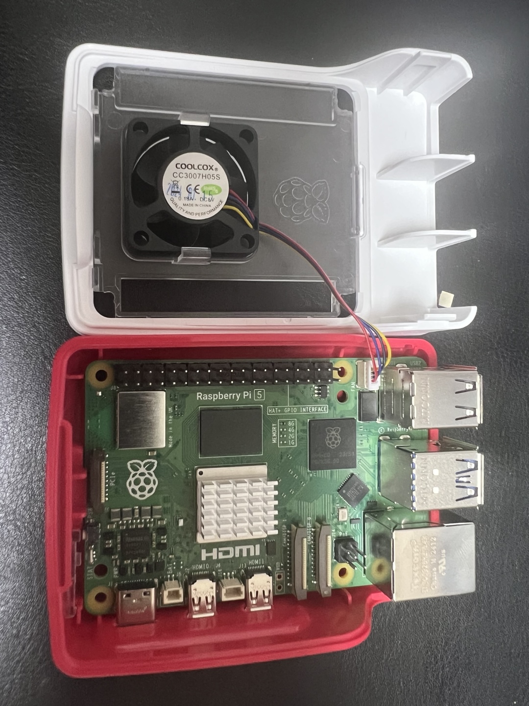
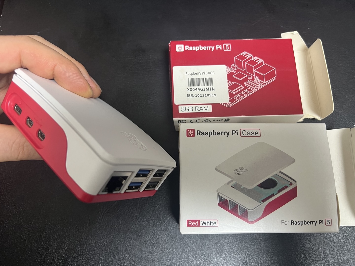
Assembling a Raspberry Pi 5 (8 GB) into the Raspberry Pi Case (Written August 4, 2025)
I. Essentials
Parts: Raspberry Pi 5 (8 GB), Raspberry Pi Case (base, frame, lid with fan), screws/standoffs, thermal pad(s).
Tools: Small Phillips screwdriver, clean workspace, optional ESD strap.
II. Quick steps
Prepare base:
Place the case base on a flat surface; add rubber feet if supplied.
Apply thermal pads:
Place pad(s) squarely on the CPU (and designated ICs if provided). Remove liners just before seating.
Seat board:
Align PCB holes with posts; ensure ports line up with cutouts and the microSD slot is unobstructed.
Secure PCB:
Install screws until snug (do not over-tighten).
Route fan lead:
Bring the lid near the board and route the cable along channels, clear of the fan blades.
Connect fan:
Insert the keyed 4-pin connector into the Raspberry Pi 5 fan header; press fully home.
Close case:
Fit the mid-frame, then snap or screw the lid. Confirm the cable is not pinched and pad contact is even.
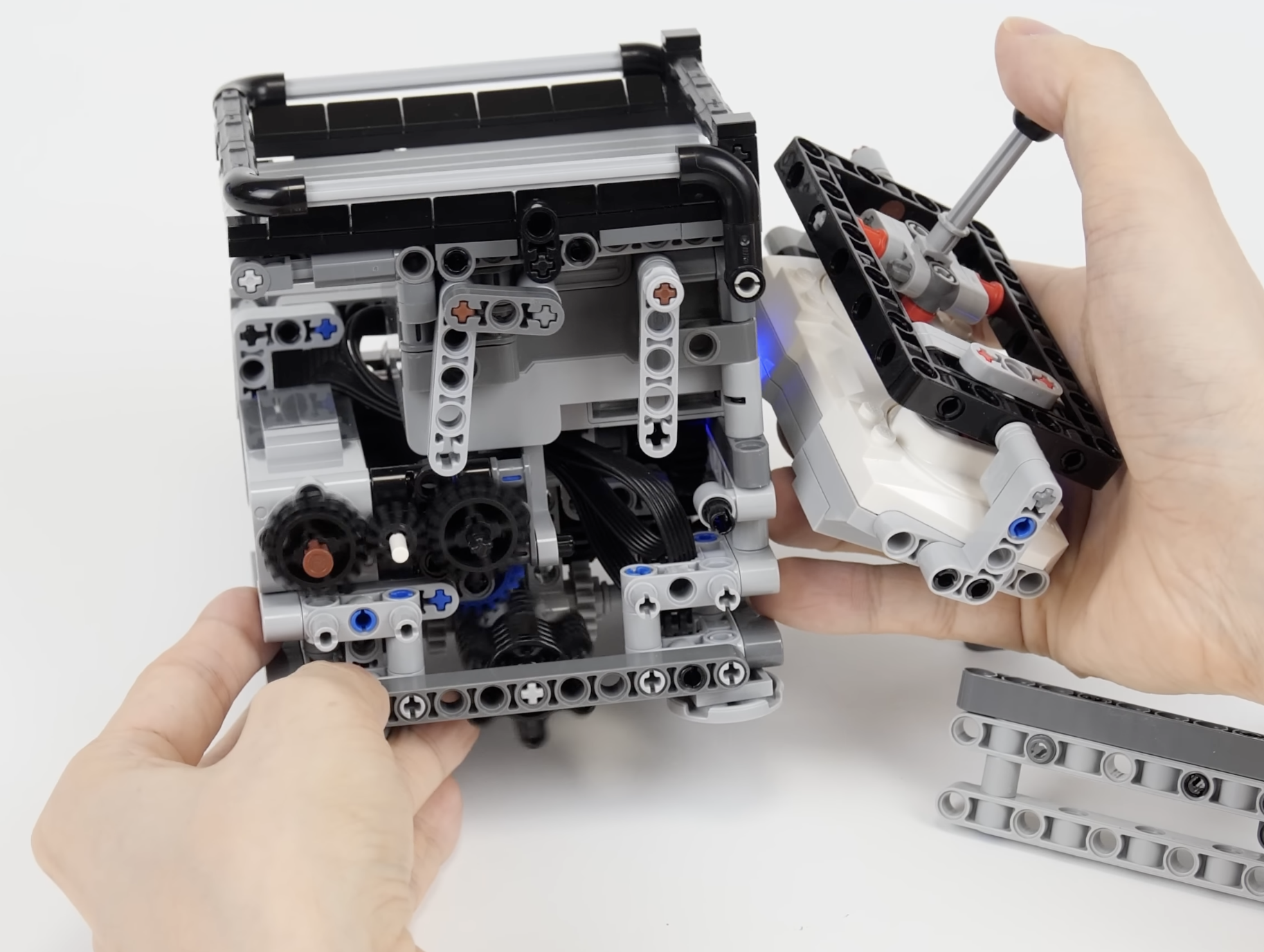
III. Internal and finished views
Left: Internal fan connection and routing. Right: Completed build with Raspberry Pi 5 and case shown together.
Written on August 4, 2025
Micro-HDMI to HDMI Type-A cable (Written August 6, 2025)
Raspberry Pi 5 is equipped with two Micro-HDMI (Type D) output ports.
To connect it to a standard monitor’s HDMI Type A input, the required cable
is called a Micro-HDMI to HDMI Type A cable.
Key specifications
Pi end: Micro-HDMI (Type D)
Monitor end: HDMI Type A
Cable name: Micro-HDMI to HDMI Type A cable
Configuration options
All-in-one cable: Single cable with Micro-HDMI plug on one end and HDMI Type A plug on the other
Adapter plus cable: Standard HDMI Type A cable paired with a small Micro-HDMI-to-HDMI Type A adapter
Selection considerations
Length: Available in various lengths (e.g. 1 m, 1.5 m, 2 m) to suit desk or rack setups
Resolution support: Ensure support for the desired output (e.g. 4K @ 60 Hz if using high-resolution displays)
Build quality: Look for certified high-speed HDMI cables to maintain signal integrity over longer runs
Written on August 6, 2025
Installing an OS to a microSD card for Raspberry Pi 5 (Written August 6, 2025)
1) Requirements
Hardware:
Raspberry Pi 5, high-quality microSD card (A1/A2, UHS-I; 16 GB minimum, 32–64 GB recommended), microSD card reader, 5 V 5 A USB-C power supply, micro-HDMI→HDMI cable, keyboard/mouse, display.
Computer:
Windows, macOS, or Linux PC with admin rights.
Software:
Raspberry Pi Imager (latest version).
2) Card preparation
Backup any data on the microSD card.
If previously used for other systems, optional quick format to FAT32/exFAT (Imager can overwrite without manual formatting).
3) OS selection (common choices)
OS
Architecture
Use case
Notes
Raspberry Pi OS (64-bit)
aarch64
General desktop/server
Recommended default (Debian-based)
Raspberry Pi OS Lite (64-bit)
aarch64
Headless, CLI only
Lower resource footprint
Third-party images
varies
Specialized workloads
Flash process is the same
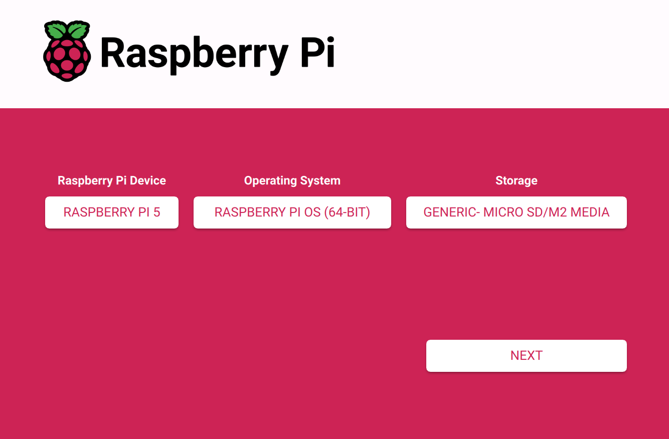
4) Flashing with Raspberry Pi Imager (Windows/macOS/Linux)
Launch
Raspberry Pi Imager
.
Select
Choose device
→
Raspberry Pi 5
.
Select
Choose OS
→
Raspberry Pi OS (64-bit)
or preferred image.
Select
Choose storage
→ the target microSD card.
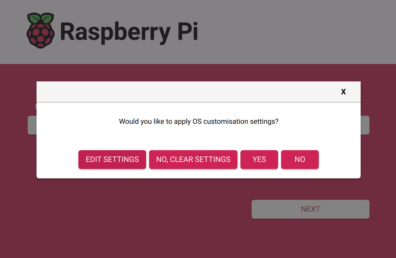
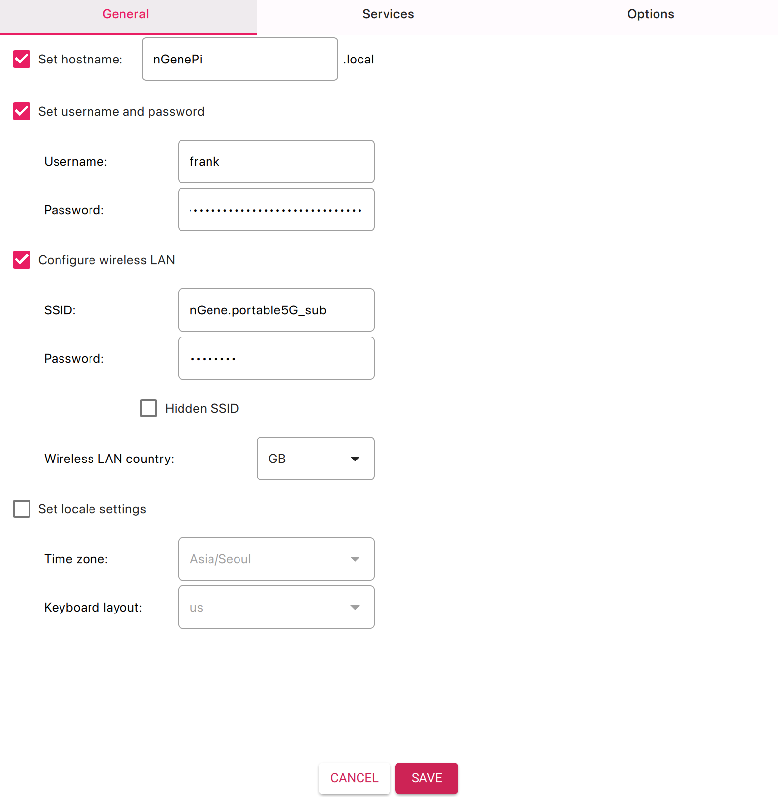
(Optional but recommended) Open settings:
Click
Settings
(gear icon) or press
Ctrl+Shift+X
/
Cmd+Shift+X
.
Set hostname
(e.g.,
raspberrypi
).
Create user
and password.
Enable SSH
(password or key).
Configure Wi-Fi
SSID/password and
Wi-Fi country
(e.g., KR).
Set
Locale
,
Keyboard
, and
Time zone
(e.g., Asia/Seoul).
Save.
Click
Write
→ confirm. The tool downloads the image, writes, and verifies it.
On completion, safely eject the card.
5) First boot on Raspberry Pi 5
Insert the microSD card into the Pi 5’s microSD slot.
Connect display (micro-HDMI to HDMI), keyboard/mouse, and network (Ethernet or configured Wi-Fi).
Apply power (5 V 5 A USB-C). Initial boot may take several minutes.
For desktop images, complete the on-screen setup wizard (if not preconfigured).
With SSH enabled in Imager settings, the Pi will join the configured Wi-Fi/Ethernet.
Connect via SSH from the same network:
ssh <username>@raspberrypi.local
Replace hostname if customized.
8) Troubleshooting checklist
No video / no boot:
Confirm official-grade power supply, reseat microSD, try a different high-quality card, reflash with verification.
Slow or unstable:
Prefer A2-rated UHS-I cards from reputable brands; avoid counterfeit media.
Wi-Fi not connecting:
Ensure correct SSID/password and country; 2.4 GHz often has better range.
Keyboard layout issues:
Set correct layout in Imager or via
raspi-config
.
9) Notes specific to Raspberry Pi 5
Boots from microSD by default; NVMe and USB boot are also supported but are outside the scope of this guide.
Two micro-HDMI (Type D) outputs support dual displays; a single monitor is sufficient for setup.
For stable performance under load, ensure adequate cooling (case fan or heatsink recommended).
Written on August 6, 2025
Modify .bashrc with Emacs and add tar4/tarX helper functions (Raspberry Pi OS) (Written August 8, 2025)
I. Purpose and scope
This document presents a clear, reproducible procedure to install a terminal-only Emacs, edit ~/.bashrc, and append two helper functions—tar4 (create .tar.gz archives) and tarX (extract .tar.gz archives). The guidance assumes Raspberry Pi OS (Debian-based) and the standard Bash shell. A verification checklist and usage examples are provided.
II. Quick reference
Command / Item
Purpose
sudo apt update
Refreshes package lists.
sudo apt install -y emacs-nox
Installs terminal-only Emacs (no GUI).
emacs ~/.bashrc
Opens the Bash configuration file.
source ~/.bashrc
Reloads the updated shell configuration.
tar4 <folder_name>
Creates folder_name.tar.gz from folder_name/.
tarX <folder_name.tar.gz>
Extracts the specified archive in the current directory.
III. Install Emacs (terminal-only)
Update package lists and install Emacs (no X/GUI dependencies):
sudo apt update
sudo apt install -y emacs-nox
IV. Edit .bashrc and add the helper functions
Open the configuration file
Open the Bash configuration file in Emacs:
emacs ~/.bashrc
In Emacs, save changes with Ctrl+x then Ctrl+s, and exit with Ctrl+x then Ctrl+c.
Append the following block (recommended location: end of file)
Optional directory preference: The first line below (cd ~/Documents) sets the default working directory to ~/Documents on every new interactive shell. Omit this line if preserving the current default startup directory is preferred.
cd ~/Documents

# ---[ tar helpers ]---------------------------------------------------------
# tar4 <folder_name>
#   Creates folder_name.tar.gz from folder_name/ (works with relative or absolute paths).
# tarX <folder_name.tar.gz>
#   Extracts the given .tar.gz archive into the current directory.
# ----------------------------------------------------------------------------
tar4() {
  if [ $# -ne 1 ]; then
    echo "Usage: tar4 <folder_name>" >&2
    return 2
  fi

  local target="$1"
  local target_dir
  local target_base
  target_dir="$(dirname "$target")"
  target_base="$(basename "${target%/}")"
  local archive="${target_base}.tar.gz"

  if [ ! -e "$target" ]; then
    echo "tar4: '$target' not found." >&2
    return 1
  fi

  if [ -e "$archive" ]; then
    read -r -p "Overwrite existing '$archive'? [y/N] " ans
    case "$ans" in
      [Yy]*) ;;
      *) echo "Aborted."; return 3 ;;
    esac
  fi

  # Create the archive so it contains just the folder name, not full paths.
  ( cd "$target_dir" && tar -czf "$OLDPWD/$archive" "$target_base" )
}

tarX() {
  if [ $# -ne 1 ]; then
    echo "Usage: tarX <folder_name.tar.gz>" >&2
    return 2
  fi

  local archive="$1"

  if [[ "$archive" != *.tar.gz ]]; then
    echo "tarX: expected a .tar.gz archive (got '$archive')." >&2
    return 2
  fi

  if [ ! -f "$archive" ]; then
    echo "tarX: '$archive' not found." >&2
    return 1
  fi

  tar -xzf "$archive"
}
# ---[ end tar helpers ]-----------------------------------------------------
Save and reload the shell configuration
After saving the changes in Emacs, reload the current shell session so the new functions are available immediately:
source ~/.bashrc
V. Verification and usage
Verify function availability
type tar4
type tarX
Each command should report a shell function definition.
Create and extract archives
# Create an archive from a directory named "myproject/"
tar4 myproject

# Extract an existing archive in the current directory
tarX myproject.tar.gz
Written on August 8, 2025
FAN & Cooling
Raspberry Pi 5: command-line notes for temperature monitoring and fan activation (Written December 25, 2025)
I. Problem statement and scope
Question
Starting from scratch on Raspberry Pi 5 (kernel 6.12.34+rpt-rpi-2712): how can current CPU temperature be shown from the command line, and how can the cooler (fan) be made to work reliably?
Answer
Raspberry Pi 5 fan behavior is controlled by the kernel thermal framework and firmware policy. Reliable results come from:
(a) confirming sensor readings,
(b) locating the correct fan control interface in /sys,
(c) setting an explicit and sufficiently aggressive fan policy in /boot/firmware/config.txt,
and (d) validating the fan curve under controlled load.
II. Show CPU temperature (print once vs. monitor continuously)
Print temperature once
Kernel thermal sensor (authoritative)
cat /sys/class/thermal/thermal_zone0/temp
Output is in millidegrees Celsius. Example: 46300 means 46.3 °C.
PWM writes were attempted, but the fan did not move. How can the correct fan controller node be identified?
Answer
Do not write to /sys/class/hwmon/hwmon*/pwm1 blindly. Instead, enumerate each hwmon device by name and locate the one labeled for fan control (commonly pwmfan on Raspberry Pi 5).
Enumerate hwmon devices by name
ls /sys/class/hwmon/
for d in /sys/class/hwmon/hwmon*; do
  echo -n "$d: "
  cat "$d/name"
done
Important note on permissions (sysfs write patterns)
Direct redirection uses the shell’s permissions, not sudo, and may fail with Permission denied.
Prefer sudo tee for writes.
Intent
Preferred form
Form to avoid
Write to a root-owned sysfs node
echo 255 | sudo tee /sys/class/hwmon/hwmon2/pwm1
sudo echo 255 > /sys/class/hwmon/hwmon2/pwm1
Avoid wildcard fan writes
.../hwmon2/pwm1 (explicit)
.../hwmon*/pwm1 (ambiguous)
IV. Make the fan work reliably (aggressive fan policy)
Question
/boot/firmware/config.txt did not contain fan parameters. What change makes the cooler engage earlier and more strongly?
Answer
Add an explicit fan policy in /boot/firmware/config.txt using dtparam=fan_temp*.
Values are in millidegrees Celsius. This section uses an aggressive policy intended to spin the fan sooner and ramp more quickly.
Edit /boot/firmware/config.txt using Emacs
Open the file with root privileges (terminal Emacs)
sudo emacs -nw /boot/firmware/config.txt
Alternative (graphical Emacs) if a desktop session is present:
sudo emacs /boot/firmware/config.txt
Add the aggressive fan policy block
Place the block under the existing [all] section or at the end of the file.
# --- Aggressive fan policy (Raspberry Pi 5) ---
dtparam=fan_temp0=40000
dtparam=fan_temp0_hyst=2000
dtparam=fan_temp1=48000
dtparam=fan_temp1_hyst=3000
dtparam=fan_temp2=55000
dtparam=fan_temp2_hyst=3000
Reboot to apply
sudo reboot
How the aggressive fan policy should behave
Threshold
Value (m°C)
Value (°C)
Expected fan behavior
fan_temp0
40000
40
Fan begins (low PWM)
fan_temp1
48000
48
Fan ramps (medium PWM)
fan_temp2
55000
55
Fan ramps further (high PWM)
Illustrative fan curve (conceptual)
Temperature (°C):  40        48        55
                  |---------|---------|----------------->
Fan policy:       OFF   ->  LOW   ->  MEDIUM   ->  HIGH

Notes:
- Hysteresis (fan_temp*_hyst) reduces rapid oscillation near a threshold.
- Actual PWM values are firmware-governed and may not be identical across boards.
V. Verify fan behavior after reboot (including “fan works but slow”)
Question
Fan activity was observed, but rotation looked slow. How can it be confirmed that the fan is working correctly and scaling under load?
Answer
Low fan speed at moderate temperature is normal. Confirmation comes from monitoring pwm1 and (if present) fan1_input while temperature increases.
cat /sys/class/hwmon/hwmon2/fan1_input 2>/dev/null || echo "fan1_input not available"
Interpret PWM numerically
PWM commonly ranges from 0 (off) to 255 (full). An observed pwm1=75 indicates approximately 29% duty cycle (75/255).
Under the aggressive policy, higher temperatures should drive higher PWM values.
Observed pwm1
Approx. duty
Typical interpretation
0
0%
Fan off
50–100
20–40%
Slow / quiet
120–180
47–71%
Moderate airflow
200–255
78–100%
High airflow
Monitor fan scaling continuously
Monitor temperature and PWM in separate terminals
# Terminal A
watch -n 1 vcgencmd measure_temp

# Terminal B
watch -n 1 cat /sys/class/hwmon/hwmon2/pwm1
Monitor temperature, PWM, enable, and RPM together (single terminal)
VI. Induce load to raise temperature (simple scripts and safe shutdown)
Question
Is there a simple way to induce CPU load to validate fan ramp behavior?
Answer
A yes-based workload is sufficient and requires no additional packages. A dedicated script (cpu_stress.sh) is convenient and was confirmed to work.
One-liner workload (no script)
Start load on all cores
for i in $(seq 1 $(nproc)); do yes > /dev/null & done
Stop the workload
pkill yes
Reusable script: cpu_stress.sh (known working form)
Create or edit with Emacs
emacs cpu_stress.sh
Script content
#!/usr/bin/env bash
set -euo pipefail

CORES=$(nproc)
PIDS=()

cleanup() {
  for pid in "${PIDS[@]}"; do
    kill "$pid" 2>/dev/null || true
  done
}
trap cleanup EXIT INT TERM

echo "CPU stress: starting ${CORES} workers"
for _ in $(seq 1 "$CORES"); do
  yes > /dev/null &
  PIDS+=("$!")
done

echo "CPU stress: running (press Enter to stop)"
read -r _

echo "CPU stress: stopping"
Make executable and run
chmod +x cpu_stress.sh
./cpu_stress.sh
Recommended validation flow (load + monitoring)
# Terminal A (monitor)
watch -n 1 vcgencmd measure_temp
# Terminal B (monitor fan PWM)
watch -n 1 cat /sys/class/hwmon/hwmon2/pwm1
# Terminal C (apply load)
./cpu_stress.sh
VII. Advanced troubleshooting notes (when expected behavior does not appear)
When pwmfan does not appear in hwmon
Confirm kernel and platform identity:
uname -r
Re-check hwmon enumeration (Section III). Fan control requires a corresponding hwmonX entry.
Verify that the cooler is physically present and connected to the Pi 5 fan header (not a GPIO pin header fan).
When the fan is spinning but “too slowly”
Confirm that temperature is only moderately above the first threshold; low PWM is normal in that region.
Confirm that pwm1 increases as temperature rises under load.
Consider lowering thresholds further only if noise constraints and airflow requirements allow it.
When writes fail with Permission denied
Use sudo tee for sysfs writes instead of shell redirection.
Avoid writing to wildcard paths; select the explicit hwmonX path identified by name.
EEPROM/bootloader sanity check
Fan control depends on current firmware. The following command prints the bootloader version:
vcgencmd bootloader_version
Reverting to a quieter fan policy
If the aggressive policy is unnecessarily loud, either remove the fan policy block or increase thresholds in /boot/firmware/config.txt, then reboot.
For example, the following is less aggressive:
# --- Quieter fan policy example ---
dtparam=fan_temp0=50000
dtparam=fan_temp0_hyst=5000
dtparam=fan_temp1=65000
dtparam=fan_temp1_hyst=5000
dtparam=fan_temp2=80000
dtparam=fan_temp2_hyst=5000
Written on December 25, 2025
Raspberry Pi 5 fan status verification from the command line (Written January 4, 2026)
This note consolidates common command-line checks for confirming whether a Raspberry Pi 5 cooling fan is recognized, spinning, and controlled automatically.
The approach relies on hwmon sysfs entries, which are typically available on Raspberry Pi OS when a PWM-capable fan is configured.
I. Objective and quick reference
Objective
Confirm the following items with minimal ambiguity:
Fan controller presence (a relevant hwmon device exists, commonly named pwmfan)
Fan rotation (a non-zero RPM appears in fan1_input)
Control mode (automatic vs. manual PWM control via pwm1_enable)
Temperature context (fan behavior correlated with SoC temperature)
Quick command checklist
Check
Command
Expected signal
Temperature
vcgencmd measure_temp
temp=…'C
hwmon devices
ls /sys/class/hwmon/
hwmon0 hwmon1 …
hwmon names
for d in /sys/class/hwmon/hwmon*; do
  echo "== $d =="
  cat "$d/name"
done
pwmfan (fan controller), plus other sensors
Fan RPM
cat /sys/class/hwmon/<fan_hwmon>/fan1_input
> 0 indicates rotation (RPM)
Control mode
cat /sys/class/hwmon/<fan_hwmon>/pwm1_enable
2 automatic, 1 manual
PWM level
cat /sys/class/hwmon/<fan_hwmon>/pwm1
0–255 (higher tends toward faster)
Key interpretation rules
fan1_input > 0 indicates the fan is spinning. pwm1_enable = 2 indicates automatic (temperature-driven) control. pwm1_enable = 1 indicates manual PWM mode (fan speed does not necessarily follow temperature).
II. Identify the correct hwmon device
List available hwmon nodes
ls /sys/class/hwmon/
Print each hwmon name and locate the fan controller
for d in /sys/class/hwmon/hwmon*; do
  echo "== $d =="
  cat "$d/name"
done
A fan controller is commonly exposed as pwmfan. Other common entries include cpu_thermal, rp1_adc, and voltage monitors.
Optional: capture the fan hwmon path for reuse
The numeric index (for example, hwmon2) may vary across boots or installations. The following snippet prints the matching directory:
for d in /sys/class/hwmon/hwmon*; do
  if [ "$(cat "$d/name")" = "pwmfan" ]; then
    echo "$d"
  fi
done
III. Confirm whether the fan is spinning (RPM)
Read fan RPM
cat /sys/class/hwmon/<fan_hwmon>/fan1_input
The value is typically expressed as RPM.
Interpret the RPM value
Observed value
Meaning
Common next step
> 0
Fan is rotating
Verify control mode (pwm1_enable) if behavior seems unexpected
0
Fan is stopped (may be normal at low temperature or low PWM)
Check temperature and control mode; consider a controlled test if needed
2649 indicates the fan is currently spinning at approximately 2,649 RPM.
IV. Check fan control mode and PWM level
Read control mode
cat /sys/class/hwmon/<fan_hwmon>/pwm1_enable
Interpret pwm1_enable
Value
Mode
Practical meaning
0
Disabled
Fan PWM control may be inactive
1
Manual PWM
PWM level is manually set; temperature-based adjustments may not occur
2
Automatic
Fan behavior is typically temperature-driven (implementation-dependent)
Read current PWM level
cat /sys/class/hwmon/<fan_hwmon>/pwm1
PWM is commonly within 0–255. A higher value generally commands a higher fan speed, subject to fan characteristics and controller behavior.
V. Correlate fan behavior with temperature
Read SoC temperature
vcgencmd measure_temp
Example output:
temp=45.5'C
Typical behavior notes
At moderate temperatures (for example, mid-40°C), either a stopped fan or a low-speed fan may be normal, depending on configuration and control mode.
Actual thresholds and curves may vary by firmware, device tree parameters, fan model, and cooling policy.
vcgencmd measure_temp
temp=45.5'C
ls /sys/class/hwmon/
hwmon0 hwmon1 hwmon2 hwmon3
for d in /sys/class/hwmon/hwmon*; do
echo "== $d =="
cat $d/name
done
== /sys/class/hwmon/hwmon0 ==
cpu_thermal
== /sys/class/hwmon/hwmon1 ==
rp1_adc
== /sys/class/hwmon/hwmon2 ==
pwmfan
== /sys/class/hwmon/hwmon3 ==
rpi_volt
cat /sys/class/hwmon/hwmon2/fan1_input
2649
cat /sys/class/hwmon/hwmon2/pwm1_enable
1
Interpretation
pwmfan indicates the fan controller is recognized by the system.
fan1_input = 2649 indicates the fan is spinning at approximately 2,649 RPM.
pwm1_enable = 1 indicates the fan is currently in manual PWM mode.
Recommended next action (restore automatic control, if desired)
sudo sh -c 'echo 2 > /sys/class/hwmon/hwmon2/pwm1_enable'
cat /sys/class/hwmon/hwmon2/pwm1_enable
A resulting value of 2 indicates automatic control has been restored.
Written on January 4, 2026
GPIO
Kernel-level driver development and debugging on Raspberry Pi 5: a practical setup guide (Written August 8, 2025)
I. Purpose and scope
This guide outlines a clean, reproducible environment on Raspberry Pi 5 for building and debugging Linux kernel device drivers.
It starts from a minimal system where a terminal editor (e.g., emacs-nox) is available and proceeds through installing build prerequisites,
headers, and tracing tools; compiling and testing an out-of-tree (OOT) module; enabling deeper kernel debug options; and establishing reliable workflows
for diagnostics. Emphasis is placed on safe, incremental steps that minimize downtime on a primary device.
II. System prerequisites and package installation
Assuming a recent Raspberry Pi OS (64-bit recommended) and a system already updated, install essential packages as follows.
Notes.dwarves provides pahole for BTF/DebugInfo. libncurses-dev supports menu-based configuration.
libelf-dev is required for module and kernel builds.
2. Kernel headers for the running kernel
sudo apt install -y raspberrypi-kernel-headers
This installs headers matching the currently running kernel and is sufficient for building out-of-tree modules without rebuilding the entire kernel.
3. Tracing, eBPF, and analysis tools (recommended)
Prefer pr_warn() / pr_err() for surfaced events; keep pr_debug() for verbose paths.
IV. Option B — full kernel build for deep debugging
Rebuilding the kernel is recommended when enabling sanitizers, KGDB, BTF, or additional tracing options.
1. Obtain sources and select the correct branch
Clone the Raspberry Pi Linux kernel tree and check out the branch that matches the running release series (e.g., rpi-6.x.y).
For Raspberry Pi 5 (BCM2712), use the BCM2712 defconfig as a baseline.
mkdir -p ~/src && cd ~/src
git clone --depth=1 https://github.com/raspberrypi/linux.git rpi-linux
cd rpi-linux
# Example: pick an rpi-6.x.y branch that aligns with `uname -r`
# git checkout rpi-6.6.y
make bcm2712_defconfig
2. Enable recommended debug options
Open the configuration UI and enable options as needed.
# Build the kernel, modules, and device trees
make -j"$(nproc)" Image modules dtbs

Install modules
sudo make modules_install

Copy artifacts (Raspberry Pi OS often uses /boot/firmware)
sudo cp arch/arm64/boot/Image /boot/firmware/kernel8.img
sudo cp -r arch/arm64/boot/dts/broadcom/.dtb /boot/firmware/
sudo cp -r arch/arm64/boot/dts/overlays/.dtbo /boot/firmware/overlays/

Optionally keep the uncompressed vmlinux with symbols
sudo cp vmlinux /boot/firmware/vmlinux
Boot safety. Maintain a known-good kernel entry. When testing, keep a fallback SD card or an alternate kernel image for quick recovery.
V. Practical debugging workflows
1. printk and dmesg
Use pr_info(), pr_warn(), pr_err() for surfaced events; reserve pr_debug() for verbose paths.
Stream logs: dmesg -w.
Rate-limit noisy logs with pr_*_ratelimited() variants.
2. Dynamic debug (per-file or per-module)
sudo mount -t debugfs none /sys/kernel/debug 2>/dev/null || true
# Enable all pr_debug in a module
echo 'module <modname> +p' | sudo tee /sys/kernel/debug/dynamic_debug/control
# Example: target a single source file
echo 'file drivers/<path>/foo.c +p' | sudo tee /sys/kernel/debug/dynamic_debug/control
3. ftrace and trace-cmd
# List available tracers and events
sudo trace-cmd list -t
sudo trace-cmd list -e

Trace function graph for 5 seconds
sudo trace-cmd record -p function_graph -T -o func.dat sleep 5
sudo trace-cmd report -i func.dat | less
4. KGDB over serial (Pi 5)
Enable KGDB and configure the serial console used for debugging. A PL011 UART (e.g., ttyAMA0) on GPIO14/15 with a USB-TTL cable is common.
Add to the kernel command line (same line): kgdboc=ttyAMA0,115200 kgdbwait. This resides in /boot/firmware/cmdline.txt on recent Raspberry Pi OS.
Connect the UART to a host and start a GDB session there with the kernel vmlinux that has symbols.
# On the host (cross or native), example with aarch64 GDB:
aarch64-linux-gnu-gdb /path/to/vmlinux
# After target waits in kgdb, connect via the serial device exported by the USB-TTL adapter.
# In GDB:
target remote /dev/ttyUSB0
During KGDB sessions, synchronize sources with the exact commit used to build the kernel to avoid line-number drift.
5. Sanitizers and fault injection
KASAN/KMSAN/KFENCE/UBSAN. Enable selectively; prefer test kernels to limit overhead.
Fault injection. Subsystems often provide debugfs knobs (e.g., fail alloc) to exercise error paths.
6. eBPF for live introspection
# Show BPF features and loadable program types
bpftool feature

Example: attach a kprobe to a symbol (requires root and kernel support)
sudo bpftool prog load myprog.o /sys/fs/bpf/myprog
sudo bpftool prog attach pinned /sys/fs/bpf/myprog kprobe <symbol>
For quick wins, bpfcc-tools provides ready-made scripts such as tcpconnect, biolatency, and runqlat to assess system behavior without rebuilding the kernel.
VI. Device Tree overlays (when hardware description must be extended)
When a driver requires additional Device Tree nodes, create a small overlay and load it at boot or dynamically.
# Compile the overlay
dtc -@ -I dts -O dtb -o myoverlay.dtbo myoverlay.dts

Install it (path may be /boot on some systems)
sudo cp myoverlay.dtbo /boot/firmware/overlays/

Enable at boot
echo "dtoverlay=myoverlay" | sudo tee -a /boot/firmware/config.txt

Or apply dynamically (where supported)
sudo dtoverlay -v myoverlay
VII. Editor and tooling enhancements (Emacs-focused)
ctags.sudo apt install -y universal-ctags; generate tags in the kernel tree with ctags -R . and enable Emacs visit-tags-table.
LSP.sudo apt install -y clangd; use lsp-mode for jump-to-definition and inline diagnostics in large codebases.
GDB. For source-level debugging of kernel with KGDB, a cross GDB (aarch64-linux-gnu-gdb) on a host or native GDB on the Pi can be used with the built vmlinux.
VIII. Troubleshooting checklist
Headers mismatch. Reinstall raspberrypi-kernel-headers after a kernel update, then reboot once if needed.
No dynamic debug output. Confirm CONFIG_DYNAMIC_DEBUG or rebuild with it; otherwise pr_debug() is compiled out.
Boot fails with custom kernel. Keep a fallback kernel and ensure DTBs/overlays match the Image.
Serial KGDB does not connect. Verify UART mapping (e.g., ttyAMA0 vs ttyS0), wiring, and baud rate.
IX. Minimal quick-start (from zero to logs)
Install prerequisites: build-essential, headers, and tracing tools as shown above.
Create the OOT module (hello_rpi.c and Makefile), then make.
sudo insmod hello_rpi.ko who="Pi5" → check dmesg.
Enable dynamic debug for the module to see pr_debug() lines.
Iterate: edit → build → reload. Move to a custom kernel only when advanced options (sanitizers, KGDB) are required.
X. Closing remarks
A disciplined workflow—starting with out-of-tree builds against matching headers, moving to targeted tracing, and escalating to a custom kernel only when necessary—provides fast iteration with minimal risk.
With the packages and patterns listed above, Raspberry Pi 5 becomes a capable, stable platform for kernel-level driver development and debugging.
Written on August 8, 2025
Raspberry Pi 5 GPIO: layout, functions, and specifications (Written August 11, 2025)
This document presents a structured overview of the Raspberry Pi 5 general-purpose input/output (GPIO) header. Emphasis is placed on physical layout, two-column pin mapping, electrical characteristics, functional interfaces, configuration guidance, and a concise comparison with Raspberry Pi 4. The 40-pin header remains broadly compatible with the Raspberry Pi HAT ecosystem while providing modern digital interfaces through the RP1 I/O controller and the BCM2712 system-on-chip.
Safety notice: GPIO lines are not 5 V tolerant. Exceeding 3.3 V on any GPIO may damage the board.
I. Overview
The Raspberry Pi 5 exposes a 2×20, 2.54 mm (0.1 inch) pitch male header. Logic levels are 3.3 V. The header integrates digital I/O and multiple serial buses (I2C, SPI, UART), pulse-width modulation (PWM), general-purpose clocks (GPCLK), and PCM/I2S for digital audio. Two pins provide 5 V power input/output, two pins provide 3.3 V from the on-board regulator, and eight pins provide ground.
II. Physical layout
Orientation and mechanics
Header: 2×20 pins, 2.54 mm pitch, through-hole; physical pin 1 is marked on the PCB (square pad and silkscreen).
Mating: standard IDC/Dupont connectors; observe keying and cable orientation to avoid inversion.
Clearance: allow vertical space for HATs and ribbon cables; avoid mechanical stress on the header.
Power and ground distribution (share of header)
Category
Count
Relative share
Notes
GPIO (reconfigurable)
28
Includes pins with alternate roles (I2C, SPI, UART, PWM, PCM, GPCLK).
Ground
8
Distributed for signal return and noise control.
3.3 V power
2
Regulated rail from on-board PMIC.
5 V power
2
Direct from USB-C input through protection circuitry.
Two-column pin mapping (physical numbering)
The header is shown as viewed from above the board, with odd-numbered pins on the left column and even-numbered pins on the right column.
Left column (odd)
Signal
Right column (even)
Signal
1
3.3 V
2
5 V
3
SDA1 (GPIO 2)
4
5 V
5
SCL1 (GPIO 3)
6
GND
7
GPIO 4 / GPCLK0 / 1-Wire
8
TXD0 (GPIO 14)
9
GND
10
RXD0 (GPIO 15)
11
GPIO 17 / RTS0 / SPI1-CE1
12
GPIO 18 / PWM0 / PCM_CLK / SPI1-CE0
13
GPIO 27
14
GND
15
GPIO 22
16
GPIO 23
17
3.3 V
18
GPIO 24
19
SPI0-MOSI (GPIO 10)
20
GND
21
SPI0-MISO (GPIO 9)
22
GPIO 25
23
SPI0-SCLK (GPIO 11)
24
SPI0-CE0 (GPIO 8)
25
GND
26
SPI0-CE1 (GPIO 7)
27
ID_SD (GPIO 0)
28
ID_SC (GPIO 1)
29
GPIO 5 / GPCLK1
30
GND
31
GPIO 6 / GPCLK2
32
PWM0 (GPIO 12)
33
PWM1 (GPIO 13)
34
GND
35
GPIO 19 / PCM_FS / SPI1-MISO / PWM1
36
GPIO 16 / CTS0 / SPI1-CE2
37
GPIO 26
38
GPIO 20 / PCM_DIN / SPI1-MOSI
39
GND
40
GPIO 21 / PCM_DOUT / SPI1-SCLK
Interface-to-pin map (concise)
Interface
Signals
Pins (BCM)
Notes
I²C-1
SDA, SCL
3 (GPIO2), 5 (GPIO3)
Primary I²C bus for peripherals.
I²C-0
SDA, SCL
27 (GPIO0), 28 (GPIO1)
HAT EEPROM; avoid reuse.
SPI0
MOSI, MISO, SCLK, CE0, CE1
19, 21, 23, 24, 26
Primary high-speed SPI.
SPI1
MOSI, MISO, SCLK, CE0/1/2
38, 35, 40, 12/11/36
Auxiliary SPI for additional devices.
UART0
TXD, RXD, CTS, RTS
8, 10, 36, 11
Console or data link.
PWM
PWM0, PWM1
12/18, 13/19
Hardware PWM pairs.
PCM/I²S
CLK, FS, DIN, DOUT
12, 35, 38, 40
Digital audio links.
GPCLK
CLK0/1/2
7, 29, 31
Reference clocks.
Per-pin capability summary (enhanced)
The table below augments the two-column map with functional class and typical uses. “Power-up” reflects default input/high-impedance behavior unless noted.
Pin
BCM
Primary role
Function class
Key alternates
Typical uses
Notes / Power-up
1
—
3.3 V
Power
—
Rail for 3.3 V devices
From on-board regulator
2
—
5 V
Power
—
Supply to HATs, drivers
Direct from USB-C input
3
GPIO2
SDA1
I²C data
GPIO, GPCLK0
Sensors, RTCs
Needs pull-up to 3.3 V
4
—
5 V
Power
—
Supply
As above
5
GPIO3
SCL1
I²C clock
GPIO, GPCLK1
Sensors, GPIO expanders
Needs pull-up to 3.3 V
6
—
GND
Ground
—
Return
Star/short return for buses
7
GPIO4
GPIO / GPCLK0
GPIO / Clock
1-Wire
1-Wire sensors, ref clock
Input at boot
8
GPIO14
TXD0
UART TX
GPIO, mini-UART TX
Console, modules
Console if enabled
9
—
GND
Ground
—
Return
—
10
GPIO15
RXD0
UART RX
GPIO, mini-UART RX
Console, modules
Console if enabled
11
GPIO17
GPIO / RTS0 / CE1
GPIO / UART / SPI
RTS0, SPI1-CE1
Flow-control, SPI CS
Input at boot
12
GPIO18
PWM0 / PCM_CLK / CE0
PWM / Audio / SPI
PWM0, SPI1-CE0
Fan/LED, audio clock
Input at boot
13
GPIO27
GPIO
GPIO
GPCLK0 (alt)
General I/O
Input at boot
14
—
GND
Ground
—
Return
—
15
GPIO22
GPIO
GPIO
—
General I/O
Input at boot
16
GPIO23
GPIO
GPIO
—
General I/O
Input at boot
17
—
3.3 V
Power
—
Accessory rail
From regulator
18
GPIO24
GPIO
GPIO
—
General I/O
Input at boot
19
GPIO10
SPI0-MOSI
SPI data
PWM (alt)
Displays, DACs
Input at boot
20
—
GND
Ground
—
Return
—
21
GPIO9
SPI0-MISO
SPI data
GPIO
Sensors, flash
Input at boot
22
GPIO25
GPIO
GPIO
—
General I/O
Input at boot
23
GPIO11
SPI0-SCLK
SPI clock
GPIO
SPI timing
Input at boot
24
GPIO8
SPI0-CE0
SPI CS
GPIO
Primary CS
Input at boot
25
—
GND
Ground
—
Return
—
26
GPIO7
SPI0-CE1
SPI CS
GPIO
Secondary CS
Input at boot
27
GPIO0
ID_SD
I²C (HAT)
GPIO (avoid)
HAT EEPROM
Reserved at boot
28
GPIO1
ID_SC
I²C (HAT)
GPIO (avoid)
HAT EEPROM
Reserved at boot
29
GPIO5
GPIO / GPCLK1
GPIO / Clock
GPCLK1
Clock output
Input at boot
30
—
GND
Ground
—
Return
—
31
GPIO6
GPIO / GPCLK2
GPIO / Clock
GPCLK2
Clock output
Input at boot
32
GPIO12
PWM0
PWM
GPIO
LED/fan control
Input at boot
33
GPIO13
PWM1
PWM
GPIO
LED/fan control
Input at boot
34
—
GND
Ground
—
Return
—
35
GPIO19
PCM_FS / PWM1 / SPI1-MISO
Audio / PWM / SPI
PWM1
Audio frame sync
Input at boot
36
GPIO16
CTS0 / SPI1-CE2
UART / SPI
GPIO
Flow-control, CS
Input at boot
37
GPIO26
GPIO
GPIO
—
General I/O
Input at boot
38
GPIO20
PCM_DIN / SPI1-MOSI
Audio / SPI
GPIO
Audio in, data out
Input at boot
39
—
GND
Ground
—
Return
—
40
GPIO21
PCM_DOUT / SPI1-SCLK
Audio / SPI
GPIO
Audio out, SPI clock
Input at boot
III. Electrical characteristics
Logic levels and protection
Logic voltage: 3.3 V CMOS. Absolute maximum on any GPIO: 0 V to 3.3 V.
ESD and abuse: input protection exists for handling only; use level shifters and buffering in mixed-voltage or noisy environments.
Current budgeting
Per-pin drive strength: software-selectable (typical range 2–16 mA). Conservative designs target ≤ 8 mA continuous per pin.
Cumulative drive: planning ≤ 50 mA across simultaneously driven pins helps limit ground bounce and heating.
3.3 V rail: provided by the on-board regulator; available current depends on system load. Reserving headroom is prudent.
5 V rail: connected to the USB-C supply through protection circuitry; available current depends on adapter capability and board activity.
Pull resistors and timing
Internal pulls: configurable pull-up or pull-down (~50–65 kΩ nominal). Pins 27/28 have fixed external pulls for HAT identification.
Rise/fall edges: series resistors (22–68 Ω) near the source can reduce ringing on fast signals such as SPI and GPCLK.
IV. Functional interfaces (concepts and practical guidance)
I2C (two-wire open-drain bus)
I2C is a multi-drop, address-based bus using open-drain signaling with pull-up resistors. It is widely used for low-to-moderate speed peripherals such as sensors, GPIO expanders, RTCs, and power monitors.
Bus
Signals / Pins
Typical speeds
Topology and notes
I2C-1 (primary)
SDA1 pin 3 (GPIO 2), SCL1 pin 5 (GPIO 3)
100 kHz, 400 kHz (higher possible with suitable wiring)
Requires pull-ups to 3.3 V; total bus capacitance and cable length should be modest for reliability.
I2C-0 (HAT ID)
SDA0 pin 27 (GPIO 0), SCL0 pin 28 (GPIO 1)
N/A (reserved)
Reserved for HAT EEPROM autodetection. Avoid repurposing in general designs.
Use cases: temperature/pressure sensors, OLED/LCD controllers, GPIO/MOSFET expanders, digital potentiometers.
Common pitfalls: missing/over-strong pull-ups, address conflicts, long ribbon cables causing clock stretching or NACKs.
SPI (synchronous full-duplex serial)
SPI provides high-speed, full-duplex links between a master and one or more slaves using separate clock and data lines plus chip-selects. It supports mode configuration (CPOL/CPHA) and achieves multi-MHz throughput over short cables.
Useful for displays, DACs/ADCs, and secondary peripherals.
Use cases: high-speed ADC/DAC, displays (TFT/OLED), flash memory, RF modules.
Common pitfalls: mismatched SPI mode, insufficient ground return, overly long cables causing clock/data skew.
UART (asynchronous serial)
UART provides simple, byte-oriented links over two wires (TXD/RXD), optionally with hardware flow control (CTS/RTS). Framing is typically 8-N-1. Logic levels are 3.3 V; RS-232 or 5 V systems require level shifting.
Use cases: console access, GNSS receivers, BLE modules, microcontroller bridges.
Common pitfalls: connecting directly to RS-232, mismatched baud/parameters, floating RXD without pull when idle.
PWM (pulse-width modulation)
PWM outputs a periodic waveform with adjustable duty cycle for power control and simple DAC-like functions. Hardware PWM channels reduce jitter compared with software-driven methods.
Channels: PWM0 on GPIO 12 or GPIO 18; PWM1 on GPIO 13 or GPIO 19.
Use cases: LED dimming, fan control (if not using the dedicated fan header), RC servos (with buffering), simple audio via low-pass filtering.
Common pitfalls: driving inductive loads directly, inadequate ground reference, aliasing into sensitive analog circuits.
PCM / I2S (digital audio)
PCM/I2S provides synchronous serial audio transport using separate clock (BCLK), frame sync (LRCLK/FS), and data lines. It enables connection to external audio codecs, ADCs, and DACs with precise timing.
Use cases: high-quality audio input/output, multichannel acquisition with suitable codecs.
Common pitfalls: LRCLK/BCLK polarity mismatches, shared pin conflicts with PWM/SPI1 alternates.
GPCLK and 1-Wire (specialized)
GPCLK outputs reference clocks derived from internal sources for external logic or as timing references. The 1-Wire overlay enables single-wire sensor networks on a designated GPIO with a pull-up resistor.
1-Wire (overlay): typically GPIO 4 (pin 7) with an external pull-up to 3.3 V.
V. Configuration and verification
Device-tree examples
# I²C-1 (pins 3/5)
dtparam=i2c=on

# SPI0 (pins 19/21/23/24/26)
dtparam=spi=on

# Primary UART
enable_uart=1

# PWM on GPIO18 (single-channel) or dual-channel variant
dtoverlay=pwm
# or
dtoverlay=pwm-2chan

# 1-Wire on GPIO4
dtoverlay=w1-gpio,gpiopin=4
Post-boot checks
List pins and functions with gpioinfo (libgpiod) or raspi-gpio get.
Confirm activated overlays with dtoverlay -l or by inspecting boot configuration.
Probe buses using i2cdetect (I2C) and loopback/scope for SPI/UART timing validation.
VI. Raspberry Pi 4 vs Raspberry Pi 5 (GPIO-specific)
The 40-pin header remains pin-compatible between Raspberry Pi 4 and Raspberry Pi 5. Changes primarily concern the I/O subsystem implementation, performance headroom, and adjacent connectors, rather than the header map itself.
Aspect
Raspberry Pi 4
Raspberry Pi 5
Impact on GPIO usage
Header pinout
2×20, classic layout
2×20, same layout
HATs and pin mappings remain compatible.
I/O controller
I/O integrated in SoC
RP1 I/O subsystem
Improved bus concurrency and responsiveness; interface names may differ slightly in OS.
Default buses on header
I2C-1, SPI0/1, UART0, PWM, PCM/ I2S
Same set exposed
No remapping required for common projects.
HAT ID pins (27/28)
Reserved for EEPROM
Reserved for EEPROM
Design guidance unchanged; avoid reuse.
Fan/header and auxiliaries
Aux cooling varied by case
Dedicated 4-pin PWM fan header
Frees PWM pins on the 40-pin header in many builds.
High-speed camera/display
Two 15-pin connectors (separate CSI/DSI)
Two high-density connectors (flexible transceivers)
No change to 40-pin GPIO, but impacts overall power/EMI planning.
Power delivery
USB-C 5 V input
USB-C with higher headroom
Greater system draw potential; budget 5 V accessories accordingly.
Written on August 11, 2025
Understanding Raspberry Pi 5 40‑Pin Header and Interfaces (Written August 13, 2025)
The Raspberry Pi 5 features a 40‑pin expansion header (J8) providing access to power, ground, and numerous GPIO and peripheral interface pins. These pins are arranged as two columns of 20 pins each, with physical pin numbers 1–40. The left column (odd-numbered pins) and right column (even-numbered pins) are shown below, along with each pin’s typical signal assignment. Notably, some pins supply fixed power (5 V or 3.3 V) or ground, while many others are configurable for different functions.
Left column (odd)
Signal
Right column (even)
Signal
1
3.3 V
2
5 V
3
SDA1 (GPIO 2)
4
5 V
5
SCL1 (GPIO 3)
6
GND
7
GPIO 4 / GPCLK0 / 1-Wire
8
TXD0 (GPIO 14)
9
GND
10
RXD0 (GPIO 15)
11
GPIO 17 / RTS0 / SPI1-CE1
12
GPIO 18 / PWM0 / PCM_CLK / SPI1-CE0
13
GPIO 27
14
GND
15
GPIO 22
16
GPIO 23
17
3.3 V
18
GPIO 24
19
SPI0-MOSI (GPIO 10)
20
GND
21
SPI0-MISO (GPIO 9)
22
GPIO 25
23
SPI0-SCLK (GPIO 11)
24
SPI0-CE0 (GPIO 8)
25
GND
26
SPI0-CE1 (GPIO 7)
27
ID_SD (GPIO 0)
28
ID_SC (GPIO 1)
29
GPIO 5 / GPCLK1
30
GND
31
GPIO 6 / GPCLK2
32
PWM0 (GPIO 12)
33
PWM1 (GPIO 13)
34
GND
35
GPIO 19 / PCM_FS / SPI1-MISO / PWM1
36
GPIO 16 / CTS0 / SPI1-CE2
37
GPIO 26
38
GPIO 20 / PCM_DIN / SPI1-MOSI
39
GND
40
GPIO 21 / PCM_DOUT / SPI1-SCLK
Note: The numbering above refers to physical pin positions. In software (e.g., the Linux gpio utility or libraries), the Broadcom GPIO numbers (BCM numbering) are typically used for the GPIO pins. For example, physical pin 3 corresponds to BCM GPIO 2. The table below summarizes where key interfaces are mapped on these pins (using physical pin numbers with BCM in parentheses):
Interface
Signals
Pins (BCM)
Notes
I²C‑1
SDA, SCL
3 (GPIO 2), 5 (GPIO 3)
Primary I²C bus for peripherals
I²C‑0
SDA, SCL
27 (GPIO 0), 28 (GPIO 1)
HAT EEPROM (reserved)
SPI0
MOSI, MISO, SCLK, CE0, CE1
19, 21, 23, 24, 26
Primary high-speed SPI bus
SPI1
MOSI, MISO, SCLK, CE0/1/2
38, 35, 40, 12/11/36
Auxiliary SPI bus (for more devices)
UART0
TXD, RXD, CTS, RTS
8, 10, 36, 11
Primary serial port (console or link)
PWM
PWM0, PWM1
12/32 (GPIO 18/12), 33/35 (GPIO 13/19)
Hardware PWM channels (two outputs)
PCM/I²S
CLK, FS, DIN, DOUT
12, 35, 38, 40
Digital audio interface (I²S)
GPCLK
CLK0, CLK1, CLK2
7, 29, 31
General-purpose clock outputs
Many GPIO pins are multiplexed, meaning each pin can perform different functions depending on software configuration. For instance, a pin might default to a GPIO (simple input/output) but can be reassigned to act as an I²C, SPI, UART, or PWM signal via the SoC’s pin multiplexer. However, a single pin can only operate in one mode at a time. Switching a pin’s function is done in software (for example, through device tree overlays or pin control settings in the operating system). This flexibility allows the 40‑pin header to support numerous interfaces, but it requires careful planning—each pin’s role is exclusive at any given moment and certain combinations of interfaces may contend for the same pins.
By default on Raspberry Pi 5, all GPIO pins are configured as inputs on power-up (high-impedance) to avoid interfering with connected hardware. A few pins serve dedicated functions from boot (such as the ID EEPROM I²C pins). The table below provides a comprehensive summary of each pin’s capabilities, default roles, and typical usage notes:
Pin
BCM
Primary role
Function class
Key alternates
Typical uses
Notes / Power-up
1
—
3.3 V
Power
—
Rail for 3.3 V devices
From on-board regulator
2
—
5 V
Power
—
Supply to HATs, modules
Direct from input (no fuse)
3
GPIO 2
SDA1
I²C data
GPIO, GPCLK0
Sensors, RTCs
Needs pull-up to 3.3 V
4
—
5 V
Power
—
Supply
Direct from input
5
GPIO 3
SCL1
I²C clock
GPIO, GPCLK1
Sensors, expanders
Needs pull-up to 3.3 V
6
—
GND
Ground
—
Return
Common ground reference
7
GPIO 4
GPIO / GPCLK0
GPIO / Clock
1-Wire
1-Wire sensors, ref clock
Input at boot
8
GPIO 14
TXD0
UART TX
GPIO, mini UART TX
Console, serial modules
Console TX (if enabled)
9
—
GND
Ground
—
Return
—
10
GPIO 15
RXD0
UART RX
GPIO, mini UART RX
Console, serial modules
Console RX (if enabled)
11
GPIO 17
GPIO / RTS0 / SPI1‑CE1
GPIO / UART / SPI
RTS0, SPI1‑CE1
Flow control, SPI CS
Input at boot
12
GPIO 18
PWM0 / PCM_CLK / SPI1‑CE0
PWM / Audio / SPI
PWM0, SPI1‑CE0
Fan or LED control, audio clock
Input at boot
13
GPIO 27
GPIO
GPIO
GPCLK0 (alt)
General I/O
Input at boot
14
—
GND
Ground
—
Return
—
15
GPIO 22
GPIO
GPIO
—
General I/O
Input at boot
16
GPIO 23
GPIO
GPIO
—
General I/O
Input at boot
17
—
3.3 V
Power
—
Accessory power
From on-board regulator
18
GPIO 24
GPIO
GPIO
—
General I/O
Input at boot
19
GPIO 10
SPI0-MOSI
SPI data
PWM (alt)
Displays, DACs
Input at boot
20
—
GND
Ground
—
Return
—
21
GPIO 9
SPI0-MISO
SPI data
GPIO
Sensors, flash
Input at boot
22
GPIO 25
GPIO
GPIO
—
General I/O
Input at boot
23
GPIO 11
SPI0-SCLK
SPI clock
GPIO
SPI timing
Input at boot
24
GPIO 8
SPI0-CE0
SPI CS
GPIO
Primary SPI CS
Input at boot
25
—
GND
Ground
—
Return
—
26
GPIO 7
SPI0-CE1
SPI CS
GPIO
Secondary SPI CS
Input at boot
27
GPIO 0
ID_SD
I²C (HAT)
GPIO (avoid)
HAT EEPROM
Reserved at boot
28
GPIO 1
ID_SC
I²C (HAT)
GPIO (avoid)
HAT EEPROM
Reserved at boot
29
GPIO 5
GPIO / GPCLK1
GPIO / Clock
GPCLK1
Clock output
Input at boot
30
—
GND
Ground
—
Return
—
31
GPIO 6
GPIO / GPCLK2
GPIO / Clock
GPCLK2
Clock output
Input at boot
32
GPIO 12
PWM0
PWM
GPIO
LED / fan control
Input at boot
33
GPIO 13
PWM1
PWM
GPIO
LED / fan control
Input at boot
34
—
GND
Ground
—
Return
—
35
GPIO 19
PCM_FS / PWM1 / SPI1-MISO
Audio / PWM / SPI
PWM1
Audio frame sync
Input at boot
36
GPIO 16
CTS0 / SPI1-CE2
UART / SPI
GPIO
Flow control, SPI CS
Input at boot
37
GPIO 26
GPIO
GPIO
—
General I/O
Input at boot
38
GPIO 20
PCM_DIN / SPI1-MOSI
Audio / SPI
GPIO
Audio in, data out
Input at boot
39
—
GND
Ground
—
Return
—
40
GPIO 21
PCM_DOUT / SPI1-SCLK
Audio / SPI
GPIO
Audio out, SPI clock
Input at boot
I. Raspberry Pi 5 Header Overview and Pin Multiplexing
(Refer to the tables above.) The Raspberry Pi 5’s GPIO header brings out a mix of power pins, ground pins, and data pins that can serve multiple purposes. Two 5 V supply pins and two 3.3 V power pins provide common voltages for attached hardware, while several ground pins are interspersed for reference and shielding. The remaining pins (labeled GPIO or with specific names like SDA1, TXD0, etc.) are driven by the Pi’s I/O controller and can be programmed for various functions. Broadly, these pins can act as:
GPIO (General Purpose I/O): Basic input or output for digital signals.
PWM outputs: Pulse-width modulated signals for controlling brightness, motor speed, etc. (on specific pins).
Special function pins: Serial communication lines for interfaces like I²C (two-wire bus), SPI (four-wire bus), UART (serial port), PCM/I²S (audio), and so on.
Each pin’s available functions are determined by the chip’s design. For example, GPIO 2 and GPIO 3 (physical pins 3 and 5) double as the I²C bus 1 lines (SDA1 and SCL1), while GPIO 14 and GPIO 15 (pins 8 and 10) serve as UART0 TX/RX (the primary serial port). Many pins also have alternate functions that can be enabled if needed—for instance, GPIO 18 (pin 12) by default can drive PWM0 for hardware PWM, or serve as a chip select for a secondary SPI interface. Understanding the pin multiplexing is crucial: one must ensure that two enabled features do not conflict on the same physical pin.
In practice, the flexibility means a single physical pin cannot be used by two interfaces at once. If a pin is reconfigured from GPIO to, say, SPI functionality, it no longer acts as a general I/O until switched back. System designers decide which functions to activate through configuration (often using a Device Tree overlay or GPIO setup code). The remainder of this document explores the common interface types accessible on the Raspberry Pi 5 and typical use cases for each, followed by examples of combining multiple interfaces in real projects.
II. Common Interface Types and Typical Uses
The Raspberry Pi 5 exposes a variety of hardware interfaces through its pins (and board connectors), each suited to different kinds of devices. The list below provides an overview of the major interface types, their purpose, and typical applications.
General-Purpose Input/Output (GPIO)
GPIO pins provide simple digital input and output capabilities without any predefined protocol. They are the most flexible interface, usable for direct control or sensing of electronics.
Primary uses: Reading buttons, switches, and digital sensors; driving LEDs or buzzers; toggling relays or transistors; implementing custom bit-banged protocols.
Advantages: Very straightforward to use with minimal setup; can interface with virtually any digital device in either input or output mode.
Limitations: No analog levels (digital on/off only without external converters); timing for complex signals must be managed by the CPU or software (no built-in timing for protocols).
Pulse Width Modulation (PWM)
PWM is a technique for simulating analog control by rapidly toggling a pin between high and low. By adjusting the duty cycle (the fraction of time the signal is high), it controls the effective power delivered to a load.
Primary uses: Dimming LEDs by varying brightness; controlling the speed of DC motors and fans; positioning servo motors (by sending repeated pulse widths); generating audio tones with simple buzzers.
Advantages: Efficiently provides variable power using digital output (no heat losses like linear control); fine-grained control over output level without needing a digital-to-analog converter; offloads repetitive toggling to hardware (for true PWM pins), reducing CPU load.
Limitations: Only certain pins support hardware PWM directly (others require software timing which can introduce jitter); PWM at low frequencies can cause audible hum or flicker in LEDs if not filtered; external components (transistors or drivers) may be needed to handle higher current loads.
Inter-Integrated Circuit (I²C)
I²C is a two-wire serial bus (using SDA for data and SCL for clock) designed for connecting multiple ICs (integrated circuits) on the same lines. It uses an addressing scheme so that many devices can share the bus.
Primary uses: Reading data from sensors (temperature, pressure, accelerometers, etc.); controlling small displays and character LCDs; communicating with real-time clocks (RTC) or port expanders; configuring smart chips like power management ICs.
Advantages: Only two lines are needed for dozens of devices, simplifying wiring; built-in support for flow control via clock stretching; well-suited for moderate-speed, command-and-response interactions.
Limitations: Maximum speed is lower than SPI (typically up to a few MHz), limiting throughput; the bus capacitance and length are limited—long wires or many devices require careful design and pull-up resistors on SDA/SCL; all devices share bandwidth, so heavy use of one device can affect others.
Serial Peripheral Interface (SPI)
SPI is a synchronous serial interface using separate lines for data output (MOSI), data input (MISO), clock (SCLK), and device select lines (CS). It is typically used for fast communication with one master and multiple slaves (each with its own CS line).
Primary uses: Driving high-speed displays (TFT LCDs, e-paper); reading/writing high-sample-rate ADCs and DACs; interfacing with external flash memory or SD card modules; controlling LED driver chips and LED matrices with high refresh rates.
Advantages: Very high throughput (tens of MHz possible) and full-duplex communication; low protocol overhead (just shift bits out/in); flexible word lengths; each device can have a dedicated chip-select for parallel operation.
Limitations: Uses more pins than I²C (at least four, plus an additional CS pin per device); wiring must accommodate all signals and a common ground, which can become complex for many devices; no built-in device addressing (requires separate CS for each device or bus multiplexing).
UART provides asynchronous serial communication over two lines (transmit and receive), typically at TTL voltage levels (3.3 V on the Pi). It is a point-to-point connection (one transmitter to one receiver) often used for text-based communication.
Primary uses: Debugging and console access (the Pi’s serial console); connecting GPS modules, Bluetooth or GSM modems; linking microcontrollers or Arduinos for simple data exchange; interfacing with serial devices like sensors or controllers that use RS-232/485 (with level shifting).
Advantages: Very simple hardware requirement (just TX, RX, and ground; optional RTS/CTS for flow control); widely supported with standard protocols (e.g., NMEA for GPS, AT commands for modems); robust for moderate distances with proper drivers or converters.
Limitations: Only one device per UART link (no multi-drop without external hardware); slower data rates compared to SPI (typically up to a few Mbps and often much less); requires precise matching of baud rate between devices; lacks inherent error checking beyond basic parity.
PCM / I²S (Digital Audio Interface)
PCM (Pulse Code Modulation) interface, commonly referred to as I²S (Inter-IC Sound), is used for streaming high-quality digital audio between devices. It consists of a bit clock (BCLK), left-right word clock (LRCLK or frame sync), and data lines.
Primary uses: Outputting stereo audio to external DACs or audio amplifiers; inputting stereo audio from ADCs or MEMS microphone arrays; connecting to codecs for both input and output audio streams; implementing multi-channel digital microphones or speakers in IoT devices.
Advantages: Provides low-jitter, synchronized audio data transfer, essential for hi-fi sound; supports multiple channels and high sample rates; standardized format makes it relatively easy to find compatible DAC/ADC chips and modules.
Limitations: Dedicated purpose (cannot be easily repurposed for non-audio data); requires continuous data stream management (the audio clock runs continuously, so software or DMA must supply data steadily); not plug-and-play — typically needs specific drivers or kernel support for audio codecs.
General-Purpose Clock (GPCLK)
GPCLK pins output a continuous clock signal at a programmable frequency. They are used when an external device or circuit needs a steady timing reference provided by the Pi.
Primary uses: Providing a reference clock to RF modules, microcontrollers, or communications circuits; generating carrier waves for experiments in modulation (FM/AM transmissions); clocking external shift registers or logic circuits in sync with the Pi.
Advantages: Hardware-generated clock ensures stable frequency and low jitter compared to software toggling; offloads timing generation from the CPU; can often select from a wide range of frequencies derived from the Pi’s PLLs (Phase-Locked Loops).
Limitations: Only a few pins can serve as GPCLK outputs, and using them may preclude other alternate functions on those pins; the clock is free-running (no innate way to transmit data or turn it off and on without reconfiguring the pin); careful analysis needed to avoid frequency conflicts if multiple GPCLKs are used.
Display Parallel Interface (DPI)
DPI is a parallel RGB interface that can drive certain LCD displays directly with a pixel clock and parallel data lines. On Raspberry Pi 5, enabling DPI repurposes a large number of GPIO pins as a high-speed parallel bus.
Primary uses: Directly connecting to TFT LCD panels or other parallel-interface displays without an HDMI or converter; providing a real-time pixel data stream for custom display applications; experimenting with generating video signals (VGA or composite via resistor DAC networks).
Advantages: Very high throughput (all pixel bits output simultaneously each clock pulse) enabling high pixel clock rates; bypasses additional controller hardware for supported panels, reducing latency; can output custom video timings not limited by standard interfaces.
Limitations: Consumes many GPIO pins (up to 24 data lines plus control signals) leaving few for other uses; requires precise timing and a continuous data stream (usually driven by dedicated hardware logic or DPI engine in the Pi); typically not used alongside other interfaces due to pin contention.
Camera Serial Interface (MIPI CSI-2) and Display Serial Interface (MIPI DSI)
CSI-2 and DSI are high-speed serial interfaces for camera and display modules, respectively. These use dedicated connectors on the Raspberry Pi board (separate from the 40-pin header) to attach camera modules or official displays using flat flex cables.
Primary uses: CSI-2 is used for connecting camera modules (like the Raspberry Pi Camera) supporting high-resolution image capture or video; DSI is used for connecting the official Pi Touchscreen display or other DSI-compatible screens, carrying high-resolution video data and touch signals.
Advantages: Extremely high bandwidth tailored for video data (multi-gigabit serial lanes) allowing for HD video and high FPS capture/display; standardized protocol means broad compatibility with sensors and displays designed for mobile devices; frees up the 40-pin header for other uses since these have dedicated connectors.
Limitations: Only available via the specific CSI/DSI connectors (cannot be remapped to GPIO pins); require specialized drivers and firmware support – users cannot easily create their own CSI/DSI devices; not suitable for general-purpose communication (only for cameras and displays).
PCIe, USB, Ethernet, and SDIO (Board-level Interfaces)
Raspberry Pi 5 introduces a PCI Express interface (via a small slot) and, like its predecessors, provides USB ports, Ethernet, and an SDIO interface for the microSD card. These are not accessed through the 40-pin header, but they represent additional I/O capabilities of the board.
Primary uses: PCIe: adding high-speed peripherals such as NVMe SSDs or specialized expansion cards; USB: connecting peripherals like mice, keyboards, Wi-Fi adapters, or external storage; Ethernet: wired networking for internet or LAN access; SDIO: communication with the onboard Wi-Fi/Bluetooth or the microSD storage.
Advantages: These interfaces follow industry standards (PCIe Gen 2 x1 on Pi 5, USB 3.0/2.0, 10/100/1000 Ethernet, SDIO) providing plug-and-play compatibility and high data throughput for their respective purposes; offloads certain tasks from the GPIO header (e.g., no need to bit-bang high-speed storage or network traffic).
Limitations: Not available through the GPIO pins (require dedicated connectors and hardware); higher power requirements for devices (e.g., USB devices may need substantial current); not modifiable in function (these are fixed to specific roles, unlike reconfigurable GPIO alternate functions).
Software-Emulated Interfaces (Bit-Banging)
In addition to the hardware interfaces above, it is possible to emulate protocols in software using GPIO pins. This technique, often called “bit-banging,” toggles GPIO lines according to the protocol timing in software, rather than using dedicated hardware controllers.
Examples: Using a single GPIO as a One-Wire bus to read temperature sensors; driving a chain of addressable LEDs (NeoPixels/WS2812) by carefully timed pulses via PWM or PCM hardware assisted DMA; implementing additional I²C or SPI buses in software when hardware ones are occupied (at lower speeds).
Advantages: Provides flexibility to implement virtually any digital protocol, even those not natively supported, using general GPIO pins; can work around limitations of available hardware channels (e.g., a third SPI bus via software if needed); useful for custom or very slow communications where precise timing is manageable by the CPU.
Limitations: Significantly CPU-intensive for high-speed signals (the processor must handle every transition, which can be unreliable under multitasking OS); timing can be inconsistent (jitter) if the system is under load, potentially violating protocol requirements; typically limited to much lower speeds than hardware implementations and may require disabling interrupts for accurate timing, which can affect system stability.
III. Combining Interface Types for Enhanced Functionality
Because the Raspberry Pi offers many interfaces simultaneously, projects often use several in concert. Using multiple interface types together can yield more sophisticated systems—for example, using I²C sensors while driving a display over SPI, and toggling a few GPIO outputs for status LEDs. The only requirement is that each function uses separate pins (or timesharing if reconfigured at different times). Below are a few examples of interface combinations, what they enable, and considerations for each:
Interface combination
Typical use case
Advantages
Potential drawbacks
GPIO + PWM
LED indicators with brightness control
Simple on/off control for some LEDs via GPIO, plus dimming capability on others via PWM; low software complexity for basic blink, with hardware-driven smooth dimming on critical channels
Limited number of hardware PWM channels (only a few pins support it); using software PWM on many GPIOs increases CPU usage
GPIO + I²C
Control panel with buttons (GPIO) and a screen or sensor hub (I²C)
Immediate, low-latency reading of button presses via GPIO; simple two-wire connection for multiple peripheral devices on I²C (e.g., display, sensor modules)
Requires pull-up resistors and careful wiring for I²C; long I²C bus lines or many devices can affect reliability (noise, capacitance issues)
GPIO + SPI
User input with physical switches and a high-speed SPI display
Debounced GPIO inputs ensure responsive control; SPI provides fast updates for graphics or data logging with minimal delay
SPI uses several GPIO pins for one device (MOSI, MISO, SCLK, CS), reducing available pin count; need to manage chip select if multiple SPI devices are present
PWM + I²C
Smart lighting system with dimmable LEDs and sensor feedback
Hardware PWM provides flicker-free LED dimming; I²C sensors (light, motion) feed data to adjust lighting in real time
PWM signals can introduce electrical noise; sensor readings might require filtering if PWM switching causes interference on supply lines
SPI + I²C
Fast display (SPI) plus multiple sensors (I²C)
High-bandwidth SPI channel handles display refresh independently; I²C bus efficiently polls various sensors using only two shared lines
Need to coordinate updates: intensive SPI communication could momentarily delay I²C sensor polling if CPU is busy; ensure sensor critical timing isn’t affected
UART + GPIO
External microcontroller with serial link and reset control
UART provides reliable two-way communication for data and commands; a dedicated GPIO can reset or trigger boot-loader mode on the external microcontroller remotely
Must sequence the GPIO toggles carefully relative to UART activity to avoid resetting at the wrong time; only one device can be on the UART line without extra hardware
I²S + GPIO
Audio output with mute control or status LED
High-quality digital audio stream flows through I²S to an external DAC/amplifier; a GPIO can serve as a mute control or indicate an audio status (e.g., audio active)
Requires synchronization between audio stream and GPIO control (e.g., muting at frame boundaries); the extra GPIO pin for control uses up one more header pin that might otherwise carry another function
GPIO + GPCLK
Custom logic device with control signals and reference clock
GPIOs allow start/stop or mode selection for the external logic (like an FPGA or CPLD); a GPCLK pin feeds a steady clock signal to synchronize that logic with the Pi’s timing
GPCLK frequency stability is high, but if the external device requires a very specific clock that conflicts with Pi’s available frequencies, a workaround is needed; dedicating a GPCLK means that pin cannot be used for other communications
Each combination above assumes that the pins for each interface are properly allocated such that they do not overlap. Thanks to the Raspberry Pi’s flexible pin multiplexing, one can often reassign certain functions to alternative pins if the defaults conflict with another needed interface (using device tree overlays or alternate channel assignments). For instance, if the primary UART TX/RX conflict with a hat, the Pi 5 has a secondary mini-UART that can be enabled on other pins.
IV. Conclusion
The Raspberry Pi 5’s 40‑pin header provides a rich set of interfaces and general I/O, enabling projects ranging from simple LED indicators to complex multi-device systems. Most GPIO header pins can serve more than one function, but only one role can be active on a given pin at any time. By carefully selecting pin functions and utilizing the Pi’s dedicated connectors (like CSI/DSI or PCIe) for specialized needs, a single Raspberry Pi can manage a combination of sensors, actuators, displays, and communication links all at once. The key is to map out which pins and interfaces are needed, taking into account the electrical requirements (voltage levels, pull-ups for I²C, series resistors for LEDs, etc.) and any interactions between them.
In summary, use basic GPIO for straightforward on/off controls and simple signaling, leverage PWM for analog-like control of brightness or motor speed, use I²C or SPI for communicating with smart peripherals (choosing SPI for bandwidth-intensive devices and I²C for simplicity and expandability), and tap into UART, I²S, or DPI when their specialized capabilities are required. The Raspberry Pi 5’s versatile interface set, combined with careful planning of pin assignments, allows it to serve as the center of a sophisticated hardware project with modest wiring and high reliability.
Written on August 13, 2025
Proper method for connecting LEDs to Raspberry Pi 5 (Written August 12, 2025)
I. Overview
When connecting light-emitting diodes (LEDs) to a Raspberry Pi 5, the inclusion of a current-limiting resistor is not optional but a necessary safeguard. The absence of this resistor can result in excessive current flow, leading to overheating of the LED and potential damage to the Raspberry Pi’s general-purpose input/output (GPIO) pins. This problem can manifest as noticeable heat, a burnt smell, and permanent hardware damage.
While previous configurations on earlier models such as the Raspberry Pi 4 may have appeared to function without such precautions, any successful operation in that manner was a result of fortunate circumstances rather than proper engineering practice.
II. Electrical characteristics of LEDs
An LED is a diode that allows current to pass in one direction, emitting light in the process. Unlike resistive loads, LEDs do not inherently regulate current; instead, they draw as much current as the source allows, limited only by their internal structure. Without an external resistor, this current can exceed safe levels, causing thermal failure.
The most relevant specifications of an LED include:
Forward voltage (Vf): The voltage drop across the LED when forward-biased, typically ranging from 1.8–2.2 V for red LEDs and 2.8–3.3 V for blue or white LEDs.
Forward current (If): The recommended operating current, generally 10–20 mA for standard indicator LEDs.
III. Calculation of the current-limiting resistor
The resistor value is calculated using Ohm’s law:
R = (VGPIO – Vf) / If
For a Raspberry Pi GPIO pin at 3.3 V, using a red LED with a forward voltage of 2.0 V and a target current of 10 mA:
R = (3.3 V – 2.0 V) / 0.01 A = 130 Ω
The nearest higher standard resistor value should be selected to ensure safety and longevity. In this case, a 150 Ω resistor would be appropriate, reducing the current to approximately 8.7 mA while still providing sufficient brightness.
IV. Recommended resistor values for common LED colors
LED color
Typical forward voltage (Vf)
Target current (mA)
Calculated resistor (Ω)
Suggested standard resistor (Ω)
Red
2.0
10
130
150
Green
2.1
10
120
150
Blue
3.0
10
30
47
White
3.0
10
30
47
V. Wiring configuration
The correct wiring sequence is as follows:
Connect the GPIO output pin to one end of the resistor.
Connect the other end of the resistor to the anode (long leg) of the LED.
Connect the cathode (short leg) of the LED to a ground (GND) pin on the Raspberry Pi.
The physical order of the resistor and LED can be interchanged in the series connection; the electrical effect remains identical.
VI. Electrical safety considerations
Maximum current per GPIO pin should not exceed 16 mA.
The total current from all GPIO pins combined should remain under 50 mA.
Resistor values should be chosen to operate below the maximum rated current for both the LED and the GPIO pin.
Written on August 12, 2025
PWM-capable pins on Raspberry Pi 5 and their usage considerations (Written August 13, 2025)
The Raspberry Pi 5 provides a set of hardware-supported Pulse Width Modulation (PWM) outputs accessible through its 40-pin header. Understanding which pins support PWM, how they are grouped into hardware channels, and their limitations is essential for effective project design. Each PWM-capable pin can be paired with any ground pin on the header for load return paths, with proper current-limiting or driver circuitry as required.
I. Overview of PWM-capable pins
PWM on Raspberry Pi is generated by dedicated hardware channels within the SoC. The Pi 5 exposes two such channels, named PWM0 and PWM1. Each channel can be output on one of two physical pins, but both pins of the same channel carry identical signals when enabled simultaneously. Independent PWM control requires the use of one pin from each channel group.
Physical pin
BCM GPIO
PWM channel
Notes on use
12
18
PWM0
Shares channel with GPIO 12 (pin 32); hardware PWM; can be paired with any GND pin for load return
32
12
PWM0
Shares channel with GPIO 18 (pin 12); hardware PWM; can be paired with any GND pin for load return
33
13
PWM1
Shares channel with GPIO 19 (pin 35); hardware PWM; can be paired with any GND pin for load return
35
19
PWM1
Shares channel with GPIO 13 (pin 33); hardware PWM; can be paired with any GND pin for load return
II. Key usage principles
Channel sharing: GPIO 12 and GPIO 18 both output PWM0. GPIO 13 and GPIO 19 both output PWM1. Two pins sharing the same channel cannot produce different PWM signals at the same time.
Independent control: To achieve two separate PWM outputs with distinct duty cycles or frequencies, select one pin from the PWM0 group and one from the PWM1 group.
Ground reference: Any ground pin on the 40-pin header can serve as the return path for the PWM load.
Electrical safety: When driving LEDs directly, always place a current-limiting resistor in series (commonly between 330 Ω and 1 kΩ). For motors, high-power LEDs, or inductive loads, use a suitable driver circuit or transistor to protect the GPIO pin.
Alternate functions: These GPIO pins may also serve other peripheral roles (e.g., audio clocks, SPI chip selects) through pin multiplexing. Using PWM may require disabling or remapping those alternate functions.
III. Practical application notes
For single-channel PWM control, either GPIO 12 (pin 32) or GPIO 18 (pin 12) may be used with any ground pin. For dual-channel PWM, combine one PWM0 pin (GPIO 12 or GPIO 18) with one PWM1 pin (GPIO 13 or GPIO 19). This arrangement enables independent modulation of two separate outputs, such as controlling both the brightness of an LED and the speed of a motor simultaneously.
Careful selection of PWM-capable pins and consideration of their shared channels ensures reliable operation and prevents conflicts. When integrated with other Raspberry Pi interfaces, ensure that pin assignments do not overlap with I²C, SPI, UART, or other active functions required by the project.
Written on August 13, 2025
gpiod
Testing GPIO functionality on Raspberry Pi 5 (BCM2712, Linux 6.12.34+rpt-rpi-2712) (Written August 12, 2025)
I. Purpose and scope
This document presents a systematic, driver-independent approach to validate GPIO functionality on Raspberry Pi 5 running a modern Raspberry Pi OS kernel (6.12.34+rpt-rpi-2712). Emphasis is placed on libgpiod command-line tools (character device interface), with complementary Pi-specific and general alternatives. The content aims to be practical for bench testing and production verification while remaining implementation-agnostic relative to in-house kernel drivers and applications.
II. Background: GPIO interfaces on modern kernels
Contemporary Linux kernels expose GPIOs via the character device nodes /dev/gpiochipN. The legacy /sys/class/gpio (sysfs) interface is deprecated and may be unavailable. The libgpiod toolkit provides a stable user-space API and CLI for querying chips and lines, setting outputs, reading inputs, and monitoring edges, without requiring vendor-specific stacks. On Raspberry Pi 5 (SoC BCM2712), header pins map to one or more gpiochip instances, and line names/offsets are discoverable at runtime.
III. Installing user-space test tools
1) libgpiod (v2) CLI
On current Raspberry Pi OS (Debian Bookworm–based), the CLI package is typically named gpiod. Installation and version check:
If a distribution ships libgpiod v1 tools instead, the binaries are usually named gpiodetect, gpioinfo, gpioget, gpioset, and gpiomon. Both v1 and v2 are covered in the usage recipes below.
2) raspi-gpio (Pi-specific inspector)
raspi-gpio is a lightweight utility for inspecting and configuring Pi pins at a low level (function select, pull-ups/downs, etc.).
sudo apt install -y raspi-gpio
raspi-gpio get
3) pigpio (daemon + tools)
pigpio provides a high-performance GPIO daemon with local and remote clients; useful for timing-sensitive tests, PWM, and waveforms without writing kernel code.
lgpio: lightweight GPIO access library/CLI (successor style to classic tools).
WiringPi (historical): now community-maintained forks only; generally not recommended for new work.
IV. Quick validation checklist (independent of in-house drivers)
Inventory chips: enumerate /dev/gpiochipN and confirm named lines are present.
Select safe pins: avoid pins claimed by overlays (I²C, SPI, UART) during GPIO tests.
Static I/O test: drive an output and read back via loopback into an input.
Edge detection: monitor rising/falling edges from a debounced source (e.g., button).
Pull controls: validate internal pull-ups/downs and active-low logic where applicable.
Pi-level inspection: cross-check with raspi-gpio to verify function/pull state.
V. libgpiod practical recipes
A) Discovering chips and lines
libgpiod v2 syntax (single front-end binary):
# List GPIO chips and basic info
gpiod list

# Detailed info for a specific chip
gpiod info gpiochip0

# List lines with names, offsets, direction, bias, consumer
gpiod line-info gpiochip0
libgpiod v1 syntax (multiple binaries):
gpiodetect
gpioinfo
gpioinfo gpiochip0
B) Reading inputs (one-off)
v2:
# Read a single line by offset or by named line
gpiod get gpiochip0 17
gpiod get --active-low gpiochip0 17
# Bias may be specified where supported:
gpiod get --bias=pull-up  gpiochip0 17
gpiod get --bias=pull-down gpiochip0 17
v1:
gpioget gpiochip0 17
gpioget --active-low gpiochip0 17
# Some v1 builds provide --bias flags; if unsupported, configure pulls via raspi-gpio
C) Driving outputs (static set/clear)
v2:
# Set line 17 high, then low (active-high)
gpiod set gpiochip0 17=1
gpiod set gpiochip0 17=0

# Configure active-low semantics if wiring is inverted
gpiod set --active-low gpiochip0 17=1
v1:
gpioset gpiochip0 17=1
gpioset gpiochip0 17=0
D) Monitoring edges
v2:
# Monitor rising and falling edges on line 17
gpiod monitor gpiochip0 17

# Optional: software debounce (in microseconds, if supported)
gpiod monitor --debounce=5000 gpiochip0 17
v1:
gpiomon gpiochip0 17
# Some builds support --rising-edge/--falling-edge/--num-events
E) Reserving lines and toggling at rate
v2:
# Drive a square wave by shell loop (for quick visibility on a scope/LED)
gpiod set --mode=signal --cycle=100000 gpiochip0 17
# If --mode is unavailable in the distro build, use a shell loop instead:
while true; do gpiod set gpiochip0 17=1; usleep 100000; gpiod set gpiochip0 17=0; usleep 100000; done
v1:
while true; do gpioset gpiochip0 17=1; usleep 100000; gpioset gpiochip0 17=0; usleep 100000; done
F) Working by line name instead of offset (when available)
Many Pi kernels annotate lines with names like GPIO17. Both v1 and v2 allow selecting by name:
gpiod get gpiochip0 GPIO17
gpiod set gpiochip0 GPIO17=1
# or
gpioget gpiochip0 GPIO17
gpioset gpiochip0 GPIO17=1
VI. Raspberry Pi–specific notes (BCM2712)
Voltage domain: All standard GPIOs are 3.3 V tolerant only; avoid 5 V.
Current: Per-pin current should remain conservative (e.g., ≤ 8 mA typical), and board-level totals should be respected to prevent brownout or damage.
Pulls and functions: Some pins have default pulls or may be claimed by overlays (I²C, SPI, UART). Disable or avoid these when performing generic GPIO tests.
Inspection: raspi-gpio get shows function and pull state at the pinmux level, providing a second opinion to libgpiod’s view.
Example: commonly used header pins (for generic tests)
Confirm device tree and kernel expose GPIO; verify permissions (consider sudo).
Resource busy when requesting a line:
Another process (daemon, overlay consumer, or application) may hold it. Inspect with gpiod line-info for the consumer field and stop the claimant.
Edges not detected:
Confirm the line is input, ensure pull-up/down is correct, and apply debounce for mechanical switches.
Unexpected logic inversion:
Use --active-low in tests or rewire to match intended polarity.
Conflicting alternate functions:
Disable I²C/SPI/UART overlays temporarily when validating generic GPIO behavior to avoid automatic claims.
IX. Worked example: loopback self-test (no drivers or apps)
The following procedure validates output drive, input readback, pulls, and edge detection using two header pins and a simple jumper. Select GPIO17 (output) and GPIO27 (input) for illustration; replace with any free pair on the target system.
Prepare wiring:
Connect GPIO17 (Pin 11) to GPIO27 (Pin 13) with a jumper.
Optional: place a series resistor (e.g., 330 Ω) for added protection.
Verify line state:
# v2
gpiod info gpiochip0 | sed -n '1,120p'
# v1
gpioinfo | sed -n '1,120p'
Set known bias on the input (if supported) and read idle level:
# v2 (pull-down so the input idles low unless driven)
gpiod get --bias=pull-down gpiochip0 27
# Expect 0 when the output is not driving high
Drive the output and observe input:
# Drive output high
gpiod set gpiochip0 17=1
# Read input (should report 1)
gpiod get gpiochip0 27
# Drive output low; read input (should report 0)
gpiod set gpiochip0 17=0
gpiod get gpiochip0 27
Edge monitoring:
# Start monitor in one terminal:
gpiod monitor gpiochip0 27

# Toggle output in another terminal:
while true; do gpiod set gpiochip0 17=1; usleep 200000; gpiod set gpiochip0 17=0; usleep 200000; done
Cross-check with raspi-gpio:
raspi-gpio get 17
raspi-gpio get 27
X. Safety considerations and good practices
All standard Raspberry Pi GPIOs are 3.3 V only. Do not expose to 5 V.
Keep per-pin currents modest (for LEDs, a 330–1 kΩ series resistor is a sensible default).
When testing mechanical switches, apply pull-ups/downs and debounce to avoid false edges.
When timing matters, avoid shell loops for precision; prefer pigpio or purpose-built tooling.
Disable overlays or services (e.g., I²C, SPI, UART, pigpio) that may automatically claim lines during generic tests.
XI. Summary
For Raspberry Pi 5 on kernel 6.12.34+rpt-rpi-2712, the most robust driver-independent validation path is the libgpiod CLI on the GPIO character devices. Begin by discovering chips and lines, select unclaimed pins, and exercise inputs/outputs and edges with concise commands. Reinforce results with raspi-gpio for pinmux insight and, where tighter timing is required, employ pigpio. The combination provides comprehensive coverage—from static logic checks and pull validation to edge timing—without relying on in-house kernel modules or application code.
Written on August 12, 2025
Ensuring GPIO functionality on Raspberry Pi 5 using gpiod (Written August 12, 2025)
I. Purpose and scope
This document describes a structured method to validate the functionality of General-Purpose Input/Output (GPIO) lines on Raspberry Pi 5 by using gpiod tools exclusively. The approach covers verification from simple LED control to interaction with other devices, ensuring a driver-independent, kernel-level test path. The intention is to provide a comprehensive methodology for hardware verification and diagnostic purposes.
II. Overview of gpiod and its role
gpiod is a modern Linux userspace interface for the GPIO character device subsystem (/dev/gpiochipN). It supersedes the deprecated sysfs interface (/sys/class/gpio) and offers both library and command-line utilities to interact with GPIO lines. On Raspberry Pi 5, gpiod allows:
Enumeration of all available GPIO chips and lines.
Reading logic levels from input-configured lines.
Driving logic levels on output-configured lines.
Monitoring edges (rising, falling, or both) for event detection.
III. Installation and environment preparation
To install the required command-line tools on Raspberry Pi OS:
This ensures the latest packaged version is available. It is recommended to run these commands with appropriate privileges (sudo) when accessing GPIO devices.
IV. Sequential validation approach
Identifying available GPIO resources
Enumerating chips and lines confirms the kernel has exposed GPIO hardware and identifies line offsets and names:
gpiod list
gpiod info gpiochip0
gpiod line-info gpiochip0
Lines reported as “unused” are preferable for functional testing to avoid conflicts with system services or overlays.
LED functionality test (output verification)
A simple LED test confirms output capability and verifies correct polarity and drive strength.
Connect an LED in series with a resistor (330–1 kΩ) between the chosen GPIO pin and ground.
By connecting two GPIO lines directly, it is possible to test input functionality without additional devices:
Assign one line as output and another as input.
Drive the output high and read the input:
gpiod set gpiochip0 17=1
gpiod get gpiochip0 27
Drive the output low and read again:
gpiod set gpiochip0 17=0
gpiod get gpiochip0 27
Matching logic states confirm signal integrity.
Edge detection and event monitoring
Testing edge events ensures interrupt-based input handling is functional:
gpiod monitor gpiochip0 27
Trigger state changes by toggling the connected output or actuating a switch. Monitor output should display timestamps and event types for each change.
Bias configuration testing
Internal pull-up or pull-down resistors can be tested using the --bias option:
gpiod get --bias=pull-up gpiochip0 27
gpiod get --bias=pull-down gpiochip0 27
This helps validate correct bias operation without requiring external resistors.
V. Expanded verification with other devices
Button input test
Wire a push button between a GPIO pin and ground.
Enable an internal pull-up resistor:
gpiod get --bias=pull-up gpiochip0 22
Press and release the button while monitoring for state changes.
Relay module control
Connect a low-voltage control input of a relay board to a GPIO pin.
Toggle the pin with gpiod set commands.
Audible relay clicks or connected load switching confirms output drive capability under load.
Sensor readout emulation
Some digital sensors output simple on/off logic.
Connect the sensor’s output to a GPIO input and monitor using gpiod monitor.
Stimulate the sensor (light, motion, temperature) and confirm appropriate edge events.
Written on August 12, 2025
Controlling an LED between GPIO17 and GPIO18 with libgpiod v1 on Raspberry Pi 5 (Written August 12, 2025)
I. Context and objective
This note provides a concise, working procedure to drive an LED connected between two GPIO lines (GPIO17 as anode and GPIO18 as cathode) using the libgpiod v1 command-line utilities on Raspberry Pi 5. The focus is on the v1 toolset where the binaries are separate executables such as gpioset, gpioget, and gpiomon, rather than a unified gpiod front-end.
II. Confirm available tools and chip
Verify that the v1 utilities are installed and identify the active GPIO chip (typically gpiochip0):
# Check tool presence and version
gpiodetect --version
which gpioset gpioget gpiomon

# Enumerate chips and inspect lines (expect "gpiochip0" on Raspberry Pi)
gpiodetect
gpioinfo gpiochip0 | head -50
If permission errors appear, prepend commands with sudo or add the user to the gpio group and re-login:
sudo usermod -aG gpio "$USER"
III. Immediate LED control with gpioset
Assume the LED anode is on GPIO17 and cathode on GPIO18 with a suitable series resistor (e.g., 330–1 kΩ).
Turn LED ON (drive GPIO17 high, GPIO18 low):
sudo gpioset gpiochip0 17=1 18=0
Turn LED OFF (both low):
sudo gpioset gpiochip0 17=0 18=0
Hold the LED ON until interrupted (keep lines reserved):
# Holds the state; press Ctrl+C to release the lines
sudo gpioset -m=wait gpiochip0 17=1 18=0
Hold for a fixed duration (e.g., 300 seconds), then release:
sudo gpioset -m=time -s=300 gpiochip0 17=1 18=0
IV. Common pitfalls and quick checks
Wrong binary name: On libgpiod v1, use gpioset (not gpiod set).
Different chip index: If gpiodetect reports gpiochip1 (or others), substitute that in commands.
Permissions: Use sudo or add the user to the gpio group.
Line in use: If a line is busy, stop services or overlays that claim it, or choose another GPIO.
Electrical caution: Raspberry Pi GPIOs are 3.3 V only; ensure a series resistor is used for the LED and keep currents within safe limits.
Written on August 12, 2025
Camera Module 3
Setup, capture, and playback guide (Written August 21, 2025)
I. Overview and prerequisites
This guide summarizes a reliable workflow to verify the Raspberry Pi Camera Module 3 on Raspberry Pi 5, resolve common “device busy” conditions, capture photos and videos (including headless operation), and play back H.264 recordings. The structure is practical and conservative; commands are presented with minimal assumptions to reduce friction during repeated use.
Platform: Raspberry Pi OS (Bookworm or later) on Raspberry Pi 5.
Camera apps:rpicam-apps (the modern replacements for the old libcamera-* tools).
Keep system updated:sudo apt update && sudo apt full-upgrade -y
Install camera tools (if missing):sudo apt install -y rpicam-apps
II. Verify camera detection
Confirm that the system detects the IMX708 sensor and supported modes before attempting capture.
rpicam-hello --list-cameras
Expect to see an entry such as imx708 with resolutions (for example, 4608×2592).
If no cameras appear, reseat the ribbon cable on both ends and ensure the correct Pi 5-compatible camera cable/adapter is used.
III. Addressing “pipeline handler in use” and freeing the device
On desktop sessions, user-level services (notably PipeWire and WirePlumber) may open /dev/media* / /dev/video* devices, preventing exclusive access for rpicam-* applications. The following steps cleanly free the camera and verify ownership.
III.a Inspect: identify which processes hold the camera
systemctl --user stop ... and mask sockets during capture; unmask/start afterward
Desktop portals
xdg-desktop-portal*
systemctl --user stop xdg-desktop-portal* (only if still holding devices)
Stale captures
rpicam-still, rpicam-vid, other camera tools
pkill -f or sudo kill -9 <PID>
IV. Capture: stills and video (headless-safe defaults)
The following commands avoid preview windows and work over SSH. Paths are relative to the current directory.
IV.a Stills
# Basic JPEG still
rpicam-still -n -o test.jpg

# With one-shot autofocus at start
rpicam-still -n --autofocus-mode auto -o af_test.jpg

# Manual focus (0.0 near → 1.0 far; example mid-distance)
rpicam-still -n --autofocus-mode manual --lens-position 0.5 -o mf_test.jpg

# Specify resolution (example 2304x1296)
rpicam-still -n --width 2304 --height 1296 -o w2304_h1296.jpg
IV.b Video (H.264 elementary stream)
# 5-second H.264 recording
rpicam-vid -n -t 5000 -o test.h264

# Record with explicit framerate (produces smoother playback after remux)
rpicam-vid -n --framerate 30 -t 10000 -o test_30fps.h264

# Save presentation timestamps for exact-time remux (optional)
rpicam-vid -n --framerate 30 --save-pts timestamps.txt -t 10000 -o timed.h264
V. Live view without a local monitor (streaming)
V.a UDP streaming (simple; VLC-friendly)
# On the Raspberry Pi (send H.264 to a receiver at <PC_IP>)
rpicam-vid -n -t 0 --inline -o udp://<PC_IP>:5000

# On the receiver (VLC)
vlc udp://@:5000 :demux=h264
V.b TCP streaming (client connects to the Pi; FFplay-friendly)
# On the Raspberry Pi (listen on port 8888)
rpicam-vid -n -t 0 --inline --listen -o tcp://0.0.0.0:8888

# On the receiver (FFplay)
ffplay tcp://<PI_IP>:8888
VI. Viewing and remuxing H.264 recordings
Raw .h264 files are elementary streams that may lack timing metadata. Many players handle them well if the demuxer is specified; otherwise, remux into MP4/MKV for smooth, universally compatible playback.
VI.d Exact-timestamp MKV (when recorded with --save-pts)
# If 'timestamps.txt' was created during capture:
mkvmerge -o test.mkv --timecodes 0:timestamps.txt test.h264
VII. One-touch helper script for reliable capture
For repeated use, the following script automates freeing the camera, performing a capture, and restoring the desktop session services. It accepts a subcommand (still or vid) and passes remaining arguments to the corresponding rpicam-* tool.
~/pi-cam-capture still -o test.jpg
~/pi-cam-capture vid   -t 10000 --framerate 30 -o test.h264
VIII. Troubleshooting checklist
Detection:rpicam-hello --list-cameras lists imx708; otherwise reseat the cable and confirm the Pi 5-compatible cable/adapter.
Exclusive access: resolve “in use by another process” by stopping/ masking PipeWire sockets and terminating stale capture processes as outlined above.
Headless preview: use -n/--nopreview or stream over UDP/TCP; preview windows require a local desktop.
Permissions: ensure the account is in the video group if access errors occur:
sudo usermod -aG video "$USER" && newgrp video
Device nodes present:ls /dev/video* and ls /dev/media* should list nodes; kernel messages can be inspected via dmesg -w during camera plug-in or boot.
Autofocus behavior: continuous AF is default; for deterministic results in fixed scenes, prefer one-shot (--autofocus-mode auto) or manual (--autofocus-mode manual + --lens-position).
High-resolution photo and video via SSH (Written August 23, 2025)
This document refines earlier guidance with explicit high-resolution settings for stills and video, while keeping commands quiet and shell-ready. The tone is intentionally modest and the structure is designed for production use on Raspberry Pi OS (Bookworm), including headless SSH scenarios.
When connected via plain SSH without a desktop session, a preview window cannot be drawn. The camera can still be opened; only the on-screen live view is unavailable. For headless tests, disable preview explicitly.
# Exercise the camera for 5 seconds without opening a window (no file is saved)
rpicam-hello -n -t 5000
In a local desktop session or an active remote desktop connected to the Pi’s desktop, a preview window is available:
# 5-second visible preview (no file is saved)
rpicam-hello -t 5000
III. File locations
Outputs are written to the current working directory unless an absolute path is specified. For example:
rpicam-still -o photo.jpg            # Saves ./photo.jpg
rpicam-still -o ~/Pictures/photo.jpg # Saves to the Pictures directory
IV. Quiet still captures (including high resolution)
The following commands are shell-ready. The environment variable in front of each command reduces non-error logs; no editor is involved. The options -n (no preview) and short -t values minimize on-screen activity and delays.
Camera Module 3’s native 16:9 still resolution is typically 4608×2592. The following commands request high resolution explicitly and raise JPEG quality (values between 90–95 are generally strong).
# Full sensor width (16:9), high quality, quiet, no preview
LIBCAMERA_LOG_LEVELS="*:ERROR" rpicam-still \
  --width 4608 --height 2592 \
  --quality 95 \
  -n -t 300 \
  -o photo_4608x2592_q95.jpg
For a 4:3-style composition (cropped/scaled from the sensor’s 16:9 native area), specify a 4:3 size:
V. Video recording to MP4 (including high resolution, with/without audio)
MP4 output is produced directly by selecting the libav path. For high resolution, raising bitrate preserves detail. The presence of audio is controlled by adding or omitting --libav-audio. When a supported microphone is connected and configured, audio is multiplexed into the MP4 file.
4) 4K UHD at 24–30 fps (3 seconds, raised bitrate)
When requesting 3840×2160, the pipeline may select a mode that limits frame rate. If 30 fps is not achievable, 24 or 25 fps are reasonable alternatives.
3) Select a specific camera when multiple sensors are present
# Identify camera indices
rpicam-hello --list-cameras

# Capture from a specific index (0 or 1 as appropriate)
LIBCAMERA_LOG_LEVELS="*:ERROR" rpicam-still -n -t 1 --camera 0 -o cam0.jpg
LIBCAMERA_LOG_LEVELS="*:ERROR" rpicam-still -n -t 1 --camera 1 -o cam1.jpg
Resolving silent MP4 audio and selecting a real microphone (Written August 23, 2025)
The following report begins with the exact commands and outputs already observed, explains what they mean, and then provides a precise, minimal procedure to obtain audible audio in MP4 recordings. The approach is systemic: confirm power integrity, attach and verify a real capture device, test it independently, and only then record with explicit device selection.
Meaning: an audio stream exists, but the bitrate (~2 kb/s) is abnormally low for 48 kHz AAC, strongly indicating that the input signal was near-zero (silence or wrong source).
Action: select a real microphone explicitly; verify that the microphone captures audible signal before invoking rpicam-vid.
[alsa @ ...] cannot open audio device plughw:1,0 (No such file or directory)
ERROR: *** libav: cannot open alsa input device plughw:1,0 ***
Meaning: the ALSA capture device plughw:1,0 does not exist on this system at capture time.
Action: enumerate real capture devices and use their exact names; do not guess indices.
II. Root-cause diagnosis (from the transcripts)
No ALSA capture hardware present: arecord -l prints only the header (“List of CAPTURE Hardware Devices”) with no “card X: … device Y” entries.
PulseAudio/PipeWire exposes only a null monitor: pactl list short sources shows auto_null.monitor as the sole source, which is not a microphone.
USB bus shows only root hubs: lsusb lists the Linux Foundation root hubs but no USB audio device.
Repeated undervoltage events: kernel messages report “Undervoltage detected!”, which can prevent USB devices (including microphones) from enumerating reliably.
III. Corrective actions in order (power → hardware → software)
1) Eliminate undervoltage
Use a 5 V/5 A supply designed for Raspberry Pi 5 and a short, low-resistance USB-C cable.
Reduce load while testing (disconnect high-draw USB peripherals; avoid unpowered hubs).
Confirm status:
vcgencmd get_throttled
# Expect 0x0 when no undervoltage/throttling is present
2) Attach a real microphone
Fastest path: connect a class-compliant USB/UAC microphone or a USB audio interface with mic input.
Alternative: enable an I²S microphone HAT by adding the appropriate dtoverlay=... in /boot/firmware/config.txt, then reboot.
3) Verify kernel detection and enumerate capture devices
lsusb
dmesg | tail -n 100
arecord -l
pactl list short sources
Goal: see at least one ALSA capture card (e.g., card 1: USB_Audio [...], device 0) or a PulseAudio source that resembles alsa_input.usb-... (avoid names containing monitor).
4) Sanity-check the microphone independently of the camera
# Replace CARD/DEV with the exact values from 'arecord -l'
MIC="plughw:CARD=USB_Audio,DEV=0"
arecord -D "$MIC" -f S16_LE -r 48000 -c 2 -d 3 /tmp/test.wav
aplay /tmp/test.wav
If silence persists, unmute and raise capture gain:
alsamixer
# F6 to select the mic’s card, M to unmute, ↑ to raise "Capture"
IV. Minimal, copy-paste recording recipes (after a mic exists)
systemctl --user restart pipewire wireplumber pipewire-pulse
sleep 2
pactl list short sources
VI. Decision table (symptom → cause → resolution)
Symptom
Likely cause
Resolution
MP4 has “Audio:” but playback is silent
Pulse default/monitor or null source captured silence
Select a real mic: ALSA --audio-source alsa --audio-device "plughw:CARD=...,DEV=..." or Pulse --audio-source pulse --audio-device <alsa_input.usb-...>
arecord -l shows no “card X: … device Y” lines
No capture hardware present
Attach a USB/UAC mic or enable an I²S mic HAT; recheck arecord -l
pactl list short sources shows only auto_null.monitor
No microphone source in Pulse/PipeWire
Connect a mic; restart pipewire/wireplumber; select a non-monitor source
ALSA error “cannot open audio device plughw:1,0”
Nonexistent device index or card name
Use the exact CARD/DEV from arecord -l; prefer name-based strings over indices
ffprobe shows AAC at ~2–32 kb/s
Near-zero input signal (silence)
Unmute/raise capture in alsamixer; verify with arecord before filming
Repeated “Undervoltage detected!” in dmesg
Insufficient power; USB instability
Use a rated 5 V/5 A PSU and quality cable; confirm vcgencmd get_throttled → 0x0
VII. Conclusion
Silent MP4 audio in this context is the natural outcome of recording from a non-microphone source while no capture hardware is present. Restoring audible sound requires three prerequisites: stable power (no undervoltage), a real microphone that the OS exposes as a capture device, and explicit device selection in rpicam-vid after the microphone has been sanity-checked. Once these are satisfied, ffprobe will report a realistic AAC bitrate (for example, ~128 kb/s when requested) and playback will contain audible audio.
Written on August 23, 2025
M.2 HAT+ and Hailo AI modules w/ Camera Module 3
Practical guide to Raspberry Pi M.2 HAT+ and Hailo AI modules (Written December 7, 2025)
This document consolidates the full discussion into one cohesive narrative: what a Raspberry Pi M.2 HAT+ enables,
what a Hailo AI module adds, how the hardware connects, the trade-offs between NVMe storage and an AI accelerator,
the degree of openness in the software stack, and a disciplined approach for robotics—especially a surgical mechanical arm concept
where safety and validation deserve the highest priority.
I. Raspberry Pi M.2 HAT+: purpose and practical uses
The Raspberry Pi M.2 HAT+ is an expansion board designed to expose a Raspberry Pi’s PCIe capability in an M.2 Key M slot.
In practice, the accessory is most relevant for platforms that provide a PCIe connection (commonly Raspberry Pi 5).
The core value is straightforward: a PCIe lane becomes usable by an M.2 device, typically an NVMe SSD or a PCIe accelerator.
What the M.2 HAT+ enables
NVMe storage support: enables an M.2 NVMe SSD (PCIe-based) to be attached for higher throughput and significantly better
random IO performance than typical microSD usage.
PCIe device expansion in M.2 form factor: enables certain M.2 PCIe devices (including AI accelerators that present as PCIe endpoints),
provided electrical keying and driver support are compatible.
Better durability under write-heavy workloads: NVMe storage typically withstands sustained writes more gracefully than many microSD cards,
reducing operational fragility in continuous services.
Representative workloads that benefit from NVMe on a Raspberry Pi
Containerized services: improved responsiveness for Docker/Podman images, logs, and layered filesystems.
Databases and indexing: better latency and IOPS for small local databases, metadata stores, and search indexes.
Media libraries and local servers: faster scanning, indexing, and metadata operations for self-hosted services.
Developer workflows: quicker builds, faster package installation, and more responsive development environments.
Capability
Primary benefit
Common examples
NVMe SSD via M.2
Higher throughput and lower latency than microSD
OS boot from NVMe, databases, container storage, local caches
PCIe M.2 devices
Specialized acceleration over PCIe
AI accelerators in M.2 form factor (subject to compatibility)
Note: The M.2 HAT+ is primarily oriented to PCIe-based M.2 devices. M.2 is a physical form factor; device protocol matters.
In most Raspberry Pi PCIe use cases, the practical target is NVMe (PCIe), not SATA M.2.
II. Hailo AI module with M.2 HAT+: what the combination means
A Hailo AI module in M.2 form factor is a PCIe-attached accelerator containing a dedicated NPU (Neural Processing Unit).
When placed on the M.2 HAT+ and connected through the Raspberry Pi’s PCIe interface, the result is an edge-AI system capable of
running computer-vision inference efficiently and with low latency.
Conceptual dataflow of the combined system
Frame acquisition: a camera provides frames to the Raspberry Pi (via CSI or USB capture paths).
Pre-processing: resizing, normalization, and format conversions occur on the Raspberry Pi.
Inference: the Hailo NPU executes the neural network inference on-device.
Post-processing and decisions: outputs such as boxes, masks, or keypoints are interpreted and acted upon by application logic.
Camera/Sensor
    |
    v
Raspberry Pi (capture + pre-processing)
    |
    v  PCIe
Hailo NPU (inference)
    |
    v
Raspberry Pi (post-processing + control logic)
    |
    v
Actuators / UI / Network / Storage
What becomes possible with Hailo attached via PCIe
Real-time computer vision: object detection, segmentation, pose estimation, tracking, and similar tasks at practical frame rates.
On-device inference without cloud dependence: improved privacy and offline operation for edge deployments.
Reduced CPU load: the Raspberry Pi CPU is freed for orchestration, control loops, networking, and safety checks.
III. One M.2 slot, two common ambitions: NVMe SSD or Hailo accelerator
The M.2 HAT+ typically provides one M.2 slot connected to the Raspberry Pi’s single PCIe lane.
This imposes a practical constraint: a single PCIe lane on a single M.2 slot generally supports one device at a time.
As a result, the M.2 HAT+ is commonly used either for an NVMe SSD or for an M.2 AI accelerator such as Hailo—not both simultaneously on the same slot.
Meaning of the constraint in day-to-day design decisions
NVMe installed: storage performance improves substantially; the M.2 slot becomes unavailable for an M.2 AI accelerator.
Hailo installed: AI inference becomes fast and efficient; the M.2 slot becomes unavailable for an NVMe SSD.
Dual need (AI + fast storage): the design must move one of the two functions to another interface or another board strategy.
Goal
M.2 HAT+ usage
Typical companion choice
Practical note
Fast local storage
NVMe SSD in M.2 slot
AI features handled by CPU/GPU or a separate AI HAT
Best for storage-centric systems
Fast AI inference
Hailo module in M.2 slot
USB 3.x SSD for bulk storage
Common for vision-first edge devices
Both AI and fast storage
One function cannot occupy the same M.2 slot
AI HAT with integrated accelerator + NVMe, or Hailo + USB SSD
Two practical ways to achieve “AI + storage” in a Raspberry Pi stack
Use M.2 for Hailo and move storage to USB: keep inference fast and predictable; accept USB storage performance as sufficient for many deployments.
Use M.2 for NVMe and choose an AI board with the accelerator integrated elsewhere: preserve the PCIe storage path while still enabling AI acceleration.
Throughput on a single PCIe lane is meaningful but finite. Practical performance depends on device, firmware, OS, and pipeline design.
For many edge scenarios, “fast enough and stable” is achieved with careful IO, efficient buffering, and modest expectations of absolute bandwidth.
IV. What the Hailo module does: dedicated AI engine (NPU) and its boundaries
The Hailo module contains a dedicated AI inference engine—an NPU designed to execute neural networks efficiently.
The Raspberry Pi CPU does not “become the AI engine” when Hailo is attached; instead, the CPU orchestrates the pipeline while the NPU performs inference.
Core functional meaning of “its own AI engine”
Inference offload: neural network computations run on the NPU rather than consuming CPU cycles.
Lower latency and higher frame rates: computer-vision tasks become feasible in real time.
Efficiency-first design: high throughput per watt is a central design goal for edge deployments.
Typical tasks suited to Hailo-class NPUs
Object detection: identifying and localizing instruments, people, vehicles, parts, defects, and other entities.
Segmentation: pixel-wise classification such as tissue vs instrument, defect regions, or lane boundaries.
Pose and keypoints: landmarks, skeletal joints, tool tips, fiducials, and structured keypoint outputs.
Tracking and multi-stage pipelines: detection feeding tracking, classification, or rules-based safety logic.
Important limitations to acknowledge
Inference-focused, not training-focused: the module is optimized to run trained models, not to train large networks.
Model compatibility depends on compilation and constraints: deployment typically requires compiling models into device-executable artifacts,
and not every model architecture is equally practical.
Not a replacement for general-purpose compute: it does not replace a CPU for control logic, safety, networking, or application orchestration.
V. How good Hailo is: performance, efficiency, and product fit
Hailo accelerators are widely positioned as high-performance, energy-efficient edge inference devices.
Published peak performance is often stated as up to 26 TOPS for Hailo-8 and up to 13 TOPS for Hailo-8L, with actual throughput
depending on model architecture, input resolution, preprocessing/postprocessing cost, and end-to-end pipeline design.
How “good” tends to show up in real projects
Real-time feasibility: detection and segmentation that feel slow on CPU become practical at stable frame rates.
Power discipline: thermal behavior is typically easier to manage than GPU-heavy alternatives.
Predictable latency: consistent timing is valuable for robotics and interactive systems.
Illustrative performance scale (conceptual, not a benchmark)
Relative inference capability (conceptual view):
Hailo-8   | ████████████████████████
Hailo-8L  | ████████████████
Pi CPU    | ██
Interpretation: acceleration is substantial for vision inference workloads; end-to-end performance remains a function of capture, preprocessing,
and post-processing design—not the accelerator alone.
Privacy- or connectivity-constrained environments: on-device inference avoids cloud transmission and improves offline resilience.
Systems requiring continuous operation: stable performance under sustained workloads with careful thermal and power design.
When a different approach may fit better
Large language models or text-heavy AI: the module is not intended for large-scale generative language workloads.
Heavily GPU-oriented pipelines: some workloads benefit from a GPU-first stack, particularly when the surrounding pipeline is already GPU-accelerated.
Unusual model architectures: deployment feasibility can be limited by compilation constraints and the availability of optimized model variants.
VI. What becomes possible with Hailo even when ChatGPT is available
ChatGPT and Hailo serve different roles. ChatGPT is optimized for language and reasoning tasks, often in a cloud-driven interaction model.
Hailo is optimized for on-device inference, particularly computer vision, and remains effective without internet connectivity.
The combination is strongest when perception runs locally and higher-level reasoning runs in an application layer that may incorporate language-model capabilities.
Capability
Hailo module
ChatGPT
Real-time camera inference
Strong (designed for it)
Not designed for continuous frame-by-frame inference
Offline operation
Strong
Often limited by connectivity and deployment model
Natural-language reasoning and drafting
Not a core function
Strong
Robotics control loops
Indirect (via perception outputs)
Indirect (via planning or code generation, not real-time control)
Privacy-sensitive local vision
Strong
Depends on deployment and data flow
Practical combined architectures
Edge perception + structured reporting: Hailo performs detection/segmentation; the application converts results into structured events
that can be summarized, logged, or narrated by language tooling.
Robotics perception + high-level planning: Hailo provides stable perception; higher-level logic manages state machines, safety envelopes,
and operator interfaces; language tooling may assist with explanation, documentation, and human-facing guidance.
VII. Open-source availability for startups: what is open, what is proprietary
The ecosystem around Hailo includes open-source components and publicly available example code, while the hardware and some parts of the toolchain remain proprietary.
For startup due diligence, it is prudent to separate “open-source code usable in production” from “vendor-controlled components required for deployment.”
Common open-source or publicly available building blocks
Runtime libraries and host APIs: HailoRT is widely used as the host-side runtime to execute compiled models on the device.
Example applications: application examples accelerate prototypes for detection, segmentation, pose estimation, and end-to-end pipelines.
Model repositories: model-zoo style assets and scripts often provide known-good starting points and deployment patterns.
Pipeline frameworks: common open-source foundations (OpenCV, GStreamer, ROS 2) remain valuable around the accelerator.
What is typically not open-source
Silicon and hardware internals: chip architecture and module hardware design are proprietary.
Firmware and low-level device specifics: some device-side components remain vendor-controlled.
Compilation toolchain details: model compilation and optimization may require vendor tooling, with licensing conditions that merit careful review.
Startup-oriented guidance for using the ecosystem responsibly
License review: confirm redistribution rights for runtime, firmware, and compiled artifacts; avoid assumptions about permissive usage.
Reproducible builds: track tool versions, compilation flags, and model inputs/outputs; treat model compilation as part of the release pipeline.
Fallback plans: maintain a CPU/GPU fallback path for degraded operation, diagnostics, or compatibility testing.
VIII. Getting started: a disciplined development path for camera-based recognition
The cleanest starting point is a camera-based application, since the Hailo module’s strongest value appears in vision inference.
The aim is to establish a stable pipeline before adding product-specific logic.
Recommended incremental build order
Hardware bring-up: confirm stable power, cooling, and physical mounting; confirm PCIe visibility at the OS level.
Runtime installation: install the runtime stack and verify the accelerator is detected and usable.
First inference: run a known-good example model to validate end-to-end inference and output interpretation.
Camera integration: verify stable frame capture, consistent FPS, and correct frame formats for preprocessing.
Latency budgeting: measure capture time, preprocess time, inference time, and postprocess time; optimize the largest contributors.
Operational hardening: add logging, health checks, watchdog behavior, and safe failure modes.
Typical pipeline concerns worth addressing early
Resolution management: select a resolution that preserves critical detail while meeting latency and throughput goals.
Post-processing cost: non-max suppression, mask decoding, and tracking can dominate CPU time if implemented inefficiently.
End-to-end stability: sustained operation testing often reveals bottlenecks or thermal constraints not visible in short demos.
IX. Surgical mechanical arm concept: using Hailo for perception, not for motion authority
In a surgical mechanical arm concept, the Hailo module is best treated as a perception accelerator.
Motion authority, safety constraints, and the control stack must remain explicit, deterministic, and verifiable.
AI inference is valuable for recognizing structures, tools, and boundaries, but it should not be treated as an unquestioned source of truth.
Surgical robotics is a high-stakes domain. Any prototype should be treated as non-clinical unless verified through rigorous engineering validation,
safety design, and appropriate regulatory pathways. AI outputs should be treated as advisory signals requiring safety gating and independent checks.
System architecture recommendation for a robotics stack
Control module (robot controller): kinematics, trajectory generation, servo loops, encoder processing, hard safety limits.
Integration and safety supervisor: transforms vision outputs into robot coordinate frames, validates constraints, rate-limits commands,
and enforces stop conditions.
Calibration and coordinate alignment (often underestimated)
Camera-to-arm calibration: map image pixels to real-world coordinates and robot frames.
Tool-tip localization validation: validate that model-reported keypoints remain consistent under lighting, occlusion, motion blur, and specular highlights.
Error modeling: quantify uncertainty; treat AI outputs as probabilistic and gate motion accordingly.
Software stack options for motion and orchestration
ROS 2 ecosystem: often used for robotics orchestration, transforms, integration, and planning (with packages such as MoveIt 2 and ros2_control).
Custom real-time controller: a dedicated microcontroller or real-time subsystem can handle motor control and safety, with the Raspberry Pi
acting as a supervisory controller.
Hybrid approach: ROS 2 for high-level planning and state management, microcontroller for hard-real-time motor loops and safety interlocks.
Suggested staged development workflow for safety and correctness
Perception validation in isolation: achieve stable inference and measurable accuracy on representative data.
Robot kinematics baseline: achieve repeatable motion under manual control with encoder verification and physical constraints.
Closed-loop behavior in simulation: integrate perception outputs into a simulated robot before physical trials.
X. Camera module compatibility: recognition is the intended usage
Hailo-based systems are most valuable when paired with a camera or image-like sensor stream.
The accelerator does not need to connect to the camera directly; the camera typically connects to the Raspberry Pi, and frames are passed to the accelerator.
This architecture supports both Raspberry Pi camera modules (CSI) and USB/industrial cameras, provided stable frame acquisition and compatible formats are achieved.
Common practical notes for camera-driven inference pipelines
CSI camera modules: often provide efficient capture paths and are convenient for compact embedded designs.
USB/industrial cameras: may simplify optics and driver selection; bandwidth and latency should be measured carefully.
Lighting and optics: in medical or precision contexts, controlled lighting and lens selection can influence accuracy more than small model tweaks.
XI. Closing summary and recommended decision framing
The Raspberry Pi M.2 HAT+ primarily exists to make the Raspberry Pi’s PCIe capability usable by an M.2 device.
That M.2 device may be an NVMe SSD for fast storage or a Hailo accelerator for fast inference. Because the PCIe path and M.2 slot are typically singular,
the design choice is often either “storage-first” or “vision-first,” with hybrid solutions available through alternate interfaces or dedicated AI boards.
Practical decision framing
Storage-first systems: choose NVMe on M.2; add AI only if needed via a separate strategy.
Vision-first systems: choose Hailo on M.2; use USB storage where required.
High-stakes robotics: treat AI as perception assistance; keep deterministic control, calibration, and safety supervision explicit and testable.
Written on December 7, 2025
Raspberry Pi + Hailo M.2: training and inference notes for echocardiography (Written January 8, 2026)
Purpose. A concise reference note summarizing how a Raspberry Pi paired with a Hailo M.2 accelerator fits into an AI workflow,
with emphasis on echocardiography (심초음파) use cases and the boundary between training and inference.
I. Executive summary
Hailo is an inference accelerator. Model weights remain fixed during runtime; training is not performed on the device.
Training occurs off-device. A PC or server performs model training and produces a deployable artifact.
Deployment requires compilation. A trained model must be quantized and compiled into a Hailo-compatible binary (commonly a .hef file).
“Providing training materials” means providing a trained model. Raw training data alone does not enable learning on Hailo.
Personal research is feasible. Echocardiography training can be done in a personal setting, but data governance, labeling quality,
and validation discipline determine practical success.
Fast execution of a pre-trained neural network on live video or sensor streams
Model training (backpropagation, weight updates)
No
Training must be performed elsewhere (PC/server); device-side learning is outside intended design
On-device fine-tuning
No
Weights are not updated at runtime
Low-power acceleration at the edge
Yes
Strong fit for embedded deployments where latency, heat, and power matter
Key principle: Training produces a model; Hailo runs the model.
III. End-to-end workflow (from data to device)
The workflow divides naturally into two phases: training/packaging and edge inference.
The Raspberry Pi typically orchestrates camera input, pre/post-processing, and application logic, while Hailo accelerates the neural network forward pass.
Training / Packaging (PC or Server)                   Edge Inference (Raspberry Pi + Hailo)
──────────────────────────────────                   ────────────────────────────────────
De-identified echo data + labels
        │
        ▼
Model training (PyTorch / TensorFlow)
        │
        ▼
Export (e.g., ONNX) + INT8 quantization
        │
        ▼
Hailo compilation  ────────────────►  Deployable artifact (.hef)
                                        │
                                        ▼
                              Runtime execution (real-time inference)
Conceptual latency contributors (illustrative; varies by model size, resolution, and pipeline design):
Raw training data (videos, images, labels) is valuable for building a model, yet it is not a runtime input to Hailo.
Hailo expects a trained and compiled model artifact.
Artifact
Produced where
Contains
Consumed where
Training dataset
Data preparation pipeline
De-identified echo clips/frames and labels
Training environment (PC/server)
Trained model
Training environment (PC/server)
Network structure + learned weights
Quantization / compilation toolchain
Compiled Hailo model (.hef)
Hailo toolchain
Hardware-ready inference graph and parameters
Raspberry Pi + Hailo runtime
Calibration set (for INT8)
Data preparation pipeline
Representative samples for quantization statistics
Quantization step (prior to compilation)
V. Feasibility of personal echocardiography training
Personal training of echocardiography models is technically feasible, particularly through transfer learning.
Practical challenges are usually driven by data access, label fidelity, and responsible use.
Responsible boundary. Research prototypes may assist exploration, yet clinical decisions require appropriate validation,
governance, and regulatory alignment. It may be prudent to treat outputs as investigational signals rather than diagnostic conclusions.
VI. Practical expectations for fast recognition and classification
When a compiled model artifact is provided to the runtime, Hailo can perform fast inference suitable for real-time recognition and classification,
subject to model complexity and the surrounding pipeline.
Speed is workload-dependent. Resolution, network depth, and post-processing can dominate end-to-end latency.
Reliability depends on data match. Training data distribution should resemble runtime acquisition characteristics
(probe type, view conventions, gain, compression, overlays).
Confidence handling matters. Low-confidence outputs benefit from safe fallback behavior (defer, gate, or request reacquisition).
VII. Common misconceptions clarified
Misconception
Clarification
“Providing training data makes Hailo learn.”
Training does not occur on Hailo; a trained and compiled model must be produced elsewhere.
“Edge deployment is only a file copy.”
Quantization, calibration, and compilation are usually required to produce a Hailo-ready artifact.
“A single model can replace the full echo workflow.”
A staged pipeline (view routing → gating → specialized models) is often more stable and easier to validate.
“High accuracy in the lab guarantees field performance.”
Acquisition variability (angle, gain, operator technique, device differences) often drives real-world error.
VIII. Training an echocardiography model focused on pulmonary circulation for Hailo deployment
The pulmonary circulation focus (폐순환) often involves the right heart, pulmonary artery flow, and Doppler-derived surrogates.
A staged approach is commonly more manageable than a single end-to-end “diagnosis” model.
Define scope and intended outputs
A narrow scope improves label quality and accelerates iteration. Suitable initial targets for pulmonary circulation include:
View routing: identify clips suitable for RV/PA assessment (e.g., PSAX at great vessels, RV inflow/outflow, A4C RV-focused)
Presence/quality gating: determine whether Doppler envelopes are measurable (signal-to-noise and alignment adequacy)
Quantitative proxy extraction (research use): values derived from clearly labeled Doppler traces or segmentation-based geometry
Pattern flags: coarse indicators such as septal flattening patterns in PSAX as a non-diagnostic cue
Output definitions benefit from explicit units, sampling windows, and clip-level versus frame-level granularity.
Assemble and de-identify data
Pulmonary circulation assessment often requires multi-modal echocardiography. Data assembly may include:
B-mode cine loops (RV size/function, septal shape, pulmonary artery views)
Color Doppler clips (jet localization and quality screening)
Spectral Doppler images/clips (PW/CW traces such as TR jet, RVOT/PA flow)
Associated measurements from structured reports (used only when governance allows and de-identification is complete)
De-identification should include pixel-burned overlays and metadata fields. Clear data-use authorization and ethical review are strongly advisable.
Design the labeling strategy
Label design is the primary determinant of whether training converges to meaningful behavior. A tiered label scheme is often effective:
Tier 1: view labels and acquisition quality labels (fast to produce, high value for routing)
Tier 2: segmentation masks for RV/LV and septum in selected views (enables geometric surrogates)
Tier 3: Doppler envelope annotations (trace mask) and key points (Vmax, acceleration time endpoints) where appropriate
Tier 4: report-derived numeric targets, only when provenance and consistency are strong
Inter-observer variability can be reduced through short labeling protocols, example libraries, and periodic adjudication.
Map targets to modalities and ground truth
Pulmonary circulation concepts often appear across multiple echo modalities. A mapping table can reduce ambiguity during labeling and training.
Target (research-oriented)
Primary modality
Model output
Ground truth source
TR spectral envelope measurability
Spectral Doppler (CW)
Quality gate (measurable / not measurable)
Expert label protocol
TR envelope extraction
Spectral Doppler (CW)
Envelope mask + key points
Manual tracing annotations
RVOT/PA flow profile extraction
Spectral Doppler (PW)
Envelope mask + timing landmarks
Manual tracing annotations
RV/LV geometry proxy (e.g., area ratio)
B-mode
Segmentation masks
Pixel masks (expert or trained annotators)
Septal flattening pattern flag
B-mode (PSAX)
Pattern probability (non-diagnostic)
Consensus label set
Numeric physiological estimates should be approached cautiously; label provenance and measurement protocol consistency are essential.
Select model architecture per modality
A multi-model pipeline is often simpler and more robust than a monolithic design.
Sub-problem
Input
Recommended model family
Output
View classification / routing
B-mode clips (sampled frames)
Lightweight CNN / mobile backbone
View label + confidence
RV/LV/septum segmentation
B-mode frames
U-Net-like segmentation network
Masks and derived geometric features
Doppler envelope extraction
Spectral Doppler images
Segmentation network (envelope mask)
Envelope trace + derived key metrics
Coarse pattern flagging
PSAX cine
Classifier with temporal pooling
Pattern probability (non-diagnostic)
For Hailo deployment, architectural simplicity and predictable tensor shapes typically improve compilation success and runtime stability.
Train with transfer learning and disciplined evaluation
Transfer learning is often effective for limited medical datasets. Evaluation discipline is essential:
Patient-level splits to reduce leakage across train/validation/test
Cross-validation when dataset size is limited
Metrics aligned to task: accuracy/F1 for views, Dice/IoU for segmentation, MAE for numeric regressions
Calibration assessment for confidence outputs used in gating
Model documentation (data version, label protocol, known failure modes) reduces future confusion and supports reproducibility.
Quantize and compile for Hailo
Hailo inference commonly benefits from INT8 quantization. Typical steps include:
Export the trained model to a supported interchange format (often ONNX)
Prepare a representative calibration set (same pre-processing as runtime)
Apply quantization (post-training or quantization-aware training, as needed)
Compile to a Hailo deployable artifact (.hef)
Accuracy drift after quantization is not unusual; targeted quantization-aware retraining may be helpful, especially for subtle Doppler patterns.
Integrate the edge pipeline on Raspberry Pi
Reliable edge performance typically depends as much on the pipeline as on the model:
Fail-safe behavior when confidence is low (defer, label as unmeasurable, or request reacquisition)
Adopt a cautious interpretation and validation posture
Pulmonary circulation inference can be sensitive to acquisition angle, respiratory variation, and operator technique.
Validation against trusted references and expert review is strongly advisable before any consequential use.
Suggested staged deliverable for pulmonary circulation. A pragmatic first milestone is a robust view router plus a Doppler quality gate,
followed by envelope extraction on a single Doppler modality (e.g., TR jet or RVOT/PA flow). This staging reduces label burden while producing
immediately useful research outputs.
IX. Quick deployment checklist
Model readiness: trained model + calibration set + compiled .hef artifact
Pipeline consistency: identical pre-processing in training and runtime
Monitoring: latency, throughput, resource usage, and drift signals
Documentation: dataset version, label protocol, known failure modes, and evaluation summaries
X. Glossary (minimal)
Term
Meaning
Training
Optimization process that learns weights from labeled data (performed on PC/server)
Inference
Forward execution of a trained model to produce predictions (accelerated by Hailo)
Quantization (INT8)
Conversion of model arithmetic to 8-bit integer-friendly representations for faster edge execution
Calibration set
Representative samples used to estimate quantization statistics
Compilation (.hef)
Toolchain step converting a model into a Hailo runtime artifact
Gating
Logic that suppresses outputs when view/quality/confidence conditions are not satisfied
Written on January 8, 2026
Standard, reproducible workflow for Hailo development on Ubuntu x86_64 and deployment on Raspberry Pi (Written February 2, 2026)
The objective of the next stage is to use an Ubuntu x86_64 machine as a stable Hailo development and build environment, then transfer only the deployment artifacts to Raspberry Pi for real-device inference. This document consolidates a standard, reproducible pipeline, including a practical approach to obtaining installation packages via command-line where feasible.
I. Recommended pipeline overview
Ubuntu x86_64 (laptop or VM)
Install Hailo SDK (parser / compiler / analyzer)
Convert and compile model (ONNX → HAR → HEF)
Run sanity checks (analysis and validation at an emulation / static level)
Organize deployment artifacts
Raspberry Pi (aarch64 / armv7l)
Install Hailo Runtime (hailort)
Place HEF + inference code
Run inference on the physical Hailo device
II. Core principles and constraints
Model compilation is performed only on Ubuntu x86_64.
Raspberry Pi is used only for runtime execution. Model compilation on Raspberry Pi is not part of the standard flow.
Hailo SDK and Hailo Runtime are distinct deliverables. The SDK targets x86_64 development hosts, while runtime targets ARM devices.
Architecture must be checked using uname -m. Kernel release strings from uname -r do not indicate CPU architecture.
Component
Purpose
Supported architecture
Install location
Hailo SDK (parser / compiler / analyzer)
Model conversion and HEF generation
x86_64 only
Ubuntu development host
Hailo Runtime (hailort)
Execute HEF on Hailo device
aarch64 / armv7l
Raspberry Pi
III. Ubuntu x86_64 host preparation
Architecture and OS sanity checks
Confirm architecture
uname -m
Expected: x86_64
Confirm OS version (recommended for reproducibility)
Confirm the interpreter path belongs to the virtual environment
which python
python -V
pip -V
IV. Hailo SDK acquisition and installation on Ubuntu x86_64
Important note on “download by command”: Hailo SDK packages are typically distributed via an authenticated portal. A fully automated download using wget or curl is only possible if an authenticated, time-limited URL (or a session cookie/token) is available. In the absence of such credentials, package retrieval must be performed manually through the portal, after which command-line installation remains fully reproducible.
Package types commonly provided
Software Suite archive: hailo_ai_sw_suite_*.tar.gz
Debian package: hailo_sdk_*.deb
Python wheel bundle (optional): *.whl
Option A — Command-line download (only if an authenticated URL is available)
Download to a dedicated directory
mkdir -p ~/Downloads/hailo_sdk
cd ~/Downloads/hailo_sdk
Download using a provided authenticated URL (placeholder)
# Example (placeholder): replace AUTHENTICATED_URL with the portal-provided signed link
wget -O hailo_ai_sw_suite.tar.gz "AUTHENTICATED_URL"
If portal authentication blocks direct download, the standard approach is to download the SDK file once via the browser and then proceed with deterministic installation steps below. This preserves reproducibility for every subsequent build and deployment operation.
Option B — Install from tar.gz suite (common “official” flow)
Extract and enter the suite directory
cd ~/Downloads/hailo_sdk
tar -xvf hailo_ai_sw_suite_*.tar.gz
cd hailo_ai_sw_suite_*
Run the installer
./install.sh
Reload environment
source ~/.bashrc
Option C — Install from .deb package (when provided)
cd ~/Downloads/hailo_sdk
sudo apt install -y ./hailo_sdk_*.deb
Resolve dependencies if required
sudo apt -f install -y
Option D — Python wheel installation (only if wheels are provided)
Install ARM runtime only (SDK is not installed on Raspberry Pi)
Verify device recognition
hailortcli fw-control identify
Run inference
python3 inference.py --hef yolov8.hef
VIII. Common failure modes to preempt
Misstep
Typical outcome
Preventive measure
Attempting model compilation on Raspberry Pi
Failure or non-standard workflow
Compile HEF only on Ubuntu x86_64
Using an ARM Ubuntu environment for SDK
SDK binaries incompatible
Verify uname -m equals x86_64
Transferring code without HEF
Runtime cannot execute a model
Always ship *.hef with inference code
PATH not applied after installation
hailo: command not found
Reload shell config or open a new terminal
Virtual environment not active for Python API use
Python import failures
Activate venv before Python-side work
IX. The single most important next objective
Establish a working Hailo SDK toolchain on Ubuntu x86_64 such that hailo compiler and hailo parser execute successfully. Once that is achieved, the remainder of the pipeline becomes straightforward: ONNX → HAR → HEF, followed by transfer of *.hef to Raspberry Pi for runtime inference.
Written on February 2, 2026
PSAX anatomy recognition on Hailo using the Docker-based Hailo AI Software Suite (Written February 2, 2026)
The Docker-based Hailo AI Software Suite enables model conversion and compilation, not anatomy recognition by itself. PSAX recognition becomes possible only after a complete, model-centric pipeline is executed. The suite primarily provides a validated x86_64 build environment required to transform a trained model into a form executable on a Hailo chip.
The Docker suite builds the “brain.”
The brain must be trained elsewhere.
The Hailo chip only executes what is given to it.
I. What the Docker suite can do and cannot do
What it can do
Provide a fully validated x86_64 build environment for Hailo
Parse trained deep-learning models (e.g., ONNX)
Compile models into HEF format for Hailo-8 / Hailo-8L
Analyze resource usage and latency
Produce deployment artifacts for Raspberry Pi or PCIe hosts
What it cannot do
Perform medical image understanding by itself
Automatically recognize PSAX anatomy without a trained model
Train neural networks
Replace dataset curation or labeling
Perform inference without a Hailo runtime and a physical device
II. What “PSAX anatomy recognition” technically means
From an AI systems perspective, PSAX recognition corresponds to one of the following tasks. Each task requires a trained neural network. The Docker suite is used after training, not instead of it.
View classification
Determine whether a given echocardiographic frame is PSAX (vs PLAX, A4C, and other standard views).
Anatomical structure detection
Detect clinically meaningful structures (e.g., LV cavity, IVS, posterior wall, papillary muscles, RV), typically by predicting object locations and classes.
Segmentation
Perform pixel-level delineation (e.g., LV myocardium or LV cavity in PSAX), producing a mask rather than a bounding box.
Clinical concept
AI representation
PSAX view
Image classification label
LV cavity
Detection box or segmentation mask
Papillary muscle
Object class (detection) or region (segmentation)
Septum
Segmented region or landmark (keypoint)
Cardiac phase
Temporal model or post-processing rule
III. AV versus PV recognition in PSAX
AV (aortic valve) versus PV (pulmonary valve) recognition is feasible, but it is not something that “Hailo” performs automatically. The model must be trained to produce that distinction. Achieving this requires providing ground-truth labels in a form that a model can learn.
In practice, the requirement “tell whether this PSAX image corresponds to AV or PV” is typically implemented in one of three ways. Beginning with classification or detection is often the most stable approach.
Implementation options for AV/PV recognition
View-level classification (frame-level labeling)
Outputs: PSAX_AV, PSAX_PV (or “AV-level” and “PV-level”).
Strength: simplest labeling workflow and fastest initial validation.
Limitation: does not provide explicit localization of where AV/PV appears within the frame.
Object detection (location + class)
Outputs: bounding boxes + classes (AV, PV).
Strength: enables on-screen overlays showing where AV or PV is recognized.
Limitation: higher labeling burden due to bounding-box creation.
Landmark / keypoint estimation
Outputs: coordinates (keypoints) representing AV and PV centers or selected anatomical landmarks.
Strength: computationally light and potentially fast on-device.
Limitation: requires strict, standardized definitions of what point is labeled; ambiguity reduces reproducibility.
IV. How to “teach” AV versus PV
The model learns AV/PV only if the training data explicitly provides AV/PV ground truth. This is the decisive step that enables recognition later on the Hailo chip. Several labeling strategies are commonly used, depending on the chosen implementation option.
Each frame provides keypoints for AV and PV locations, typically one point per valve.
Example schema:
AV_x, AV_y, PV_x, PV_y
If a structure is not visible, sentinel values can be used (e.g., -1).
This approach can be efficient but requires strict, written definitions of what constitutes the labeled point to prevent drift in annotation practice.
V. Labeling tools and practical requirements
Any labeling tool can be used, provided it satisfies practical requirements for medical imaging workflows:
Fast frame-by-frame navigation
Intuitive class selection (AV / PV)
Export into standard formats (CSV / YOLO / COCO)
In practice, view classification can be performed via folder-based categorization or CSV indexing, while detection requires a tool supporting bounding-box annotation and export in standard formats.
VI. End-to-end pipeline using the Docker suite
The Docker suite becomes relevant at the model conversion and compilation stage. The complete pipeline is as follows.
View standardization (depth, orientation, gain normalization)
Output:
Training dataset suitable for PyTorch or TensorFlow
Step 3: Train the model outside Docker
Typical environments:
GPU workstation
Research server
Cloud training environment
Common choices:
PyTorch + custom CNN
YOLO-based detector (for AV/PV or anatomy landmarks)
Lightweight U-Net variant (for segmentation)
Output:
Trained model exported to ONNX
Step 4: Use the Docker suite for model conversion and compilation
This is where hailo8_ai_sw_suite_2025-10_docker.zip is used.
Within the Docker container, the following actions are performed:
Load the ONNX model
Parse the model into Hailo’s intermediate format (HAR)
Apply hardware-aware compilation
Generate a HEF file
Result:
A hardware-optimized executable model (HEF) for the Hailo chip
Step 5: Validate inside the Docker environment
The suite allows:
Static analysis of layer mapping
Memory and SRAM usage inspection
Latency estimation
This confirms feasibility of the PSAX AV/PV model on Hailo hardware before deployment.
Step 6: Deploy to the target device and run inference
Transfer the HEF file to Raspberry Pi or a PCIe host.
Install Hailo Runtime.
Run inference using Python or C++.
The Hailo chip now executes PSAX recognition (including AV/PV classification or detection), exactly as defined by the trained model.
VII. Quality rules that preserve reproducibility in clinical labeling
PSAX appearance varies significantly by level and by probe rotation/tilt, and boundaries can become ambiguous. Therefore, written labeling rules are essential for clinical correctness and engineering reproducibility.
Minimum recommended labeling rules
PSAX_AV should include only frames where the aortic valve level is clearly identified.
PSAX_PV should include only frames where the pulmonary valve / RVOT level is clearly identified.
Ambiguous frames should be labeled UNCERTAIN and excluded from training or managed as a separate class.
Within the same patient, avoid using every consecutive frame indiscriminately; prefer representative frames and maintain class balance.
VIII. Practical recommendation: the most stable starting point
For PSAX AV/PV recognition on Hailo, the most stable and reproducible approach is the following separation of concerns:
Train the model externally, with full clinical control
Export the trained model to ONNX
Use the Docker Software Suite exclusively for conversion, compilation, and validation
Treat the Hailo chip as a deterministic inference engine
This separation supports clinical correctness, engineering reproducibility, and long-term maintainability.
IX. A realistic MVP path with the lowest failure risk
The most pragmatic early implementation is to start with two-class frame-level classification:
PSAX_AV vs PSAX_PV
Once stable performance is achieved, expansion to object detection can provide localization and on-frame overlays indicating where AV/PV is recognized. This stepwise approach tends to minimize failure modes while preserving clinical interpretability.
X. Possible next focused guidance
Any of the following topics can be expanded with precise, technical detail:
PSAX AV/PV classification model design (lightweight, Hailo-friendly)
Object detection vs segmentation trade-offs for AV/PV in PSAX
ONNX export constraints and model-shaping strategies for Hailo compilation
Post-processing strategies for echocardiography (temporal smoothing, confidence gating)
End-to-end Raspberry Pi + camera + Hailo pipeline for echo video inference
Written on February 2, 2026
Reproducible Hailo workflow after downloading the Docker-based SDK (with troubleshooting) (Written February 3, 2026)
This document consolidates a stable, repeatable workflow starting from the point where the Hailo Docker-based Software Suite has already been downloaded (for example, hailo8_ai_sw_suite_2025-10_docker.zip). The goal is to compile a trained AV/PV PSAX model into a .hef artifact on an Ubuntu x86_64 host, then deploy that artifact to Raspberry Pi for device inference. Common troubleshooting steps encountered during Docker installation and daemon startup are included for reliability.
What creates AV/PV recognition
Where it happens
Primary artifact
What it is not
Model training (teaches AV vs PV)
Training environment (CPU/GPU)
ONNX
Hailo compilation
Model compilation for Hailo
Ubuntu x86_64 using Hailo Docker suite
HEF
Training
Model execution on hardware
Raspberry Pi + Hailo Runtime
Inference outputs
Compilation
Key correction: Recognition capability is delivered by the .hef model artifact. A .deb is used to install runtime/driver components, not to “store” AV/PV intelligence.
Raspberry Pi runs HEF using Hailo Runtime and an inference application.
II. Host prerequisites (Ubuntu x86_64)
Architecture and OS confirmation
uname -m
Expected: x86_64
cat /etc/os-release
Confirm VERSION_CODENAME (for example, noble/jammy/focal).
Working directories (recommended convention)
mkdir -p ~/hailo/{sdk,models,deploy,app,bundle}
ls -lah ~/hailo
III. Docker installation (practical, minimal friction)
Docker can be installed from the Ubuntu repository as docker.io. This approach is often sufficient for running Hailo’s Docker image, especially when Docker CE packages are not visible in APT.
IV. Load the Hailo Docker image from the downloaded SDK ZIP
After downloading the Hailo Docker suite ZIP, two files are commonly present after extraction: a Docker image archive (.tar.gz) and a helper script (.tar.sh). The recommended path is to load the image archive directly.
Place and extract the ZIP
mv ~/Downloads/hailo8_ai_sw_suite_2025-10_docker.zip ~/hailo/sdk/
cd ~/hailo/sdk
unzip -o hailo8_ai_sw_suite_2025-10_docker.zip
ls -lah
If a message such as No GPU chosen or No GPU connected appears, this is commonly an informational notice. The decisive check is whether hailo parser/compiler/analyze help pages display correctly.
Confirm mounted directories are visible
ls -lah /workspace/models
ls -lah /workspace/deploy
ls -lah /workspace/app
VI. Produce the ONNX model (training outside the Hailo Docker suite)
AV/PV recognition requires a trained model. The most reliable initial scope is two-class frame-level classification: PSAX_AV versus PSAX_PV. Training and ONNX export should be completed on the host (outside the Hailo Docker container).
Create training scripts under ~/avpv_train/ (any stable classifier is acceptable; MobileNet-class models are frequently suitable for embedded inference).
After training completes, produce an ONNX export named model_avpv_psax.onnx.
Place the exported ONNX into the Hailo models directory
cp /path/to/model_avpv_psax.onnx ~/hailo/models/
ls -lh ~/hailo/models/
VII. Compile ONNX to HEF inside the Hailo container (ONNX → HAR → HEF)
This is the Hailo-specific build stage. The output .hef is the artifact that will be deployed to Raspberry Pi.
Inside the container: parse ONNX to HAR
cd /workspace
ls -lh models/

hailo parser onnx models/model_avpv_psax.onnx \
  --hw-arch hailo8 \
  --output deploy/avpv_psax.har
ONNX model exists at ~/hailo/models/model_avpv_psax.onnx.
HEF is produced at ~/hailo/deploy/avpv_psax.hef.
Raspberry Pi runs Hailo Runtime and can identify the Hailo device via hailortcli.
Deployment copies .hef and application code; inference executes on-device.
Written on February 3, 2026
Reproducible Hailo DFC build notes (Ubuntu x86_64 → Raspberry Pi 5 + Hailo-8L) (Written February 7, 2026)
This note records a working sequence for rebuilding a stable Hailo development environment on Ubuntu x86_64, exporting a simple ONNX model, and compiling it into deployment artifacts for a Raspberry Pi 5 with a Hailo-8L module. The goal is fast resumption after interruptions, with minimal re-discovery of prior steps.
The practical objective is a deterministic build loop: a stable Ubuntu x86_64 environment produces a compiled .hef, and only deployment artifacts are transferred to Raspberry Pi for runtime inference on the physical Hailo-8L device.
Version pinning inside the DFC virtual environment (critical)
Pin protobuf and ONNX to versions compatible with the Hailo SDK client shipped inside DFC 5.2.0.
Pip may print resolver warnings; the pins remain important for runtime correctness of the Hailo tools.
Optional: if warnings about deprecated pkg_resources appear and noise reduction is desired,
a conservative setuptools pin may help.
pip install "setuptools<81"
IV. ONNX export that the DFC parser accepts
A recurring obstacle was the DFC parser rejecting ONNX files exported with PyTorch Dynamo. The accepted pattern is a legacy (non-dynamo) export. Opset 18 was selected to avoid brittle down-conversion and to match the observed exporter behavior.
Export a minimal test model (legacy exporter, opset 18)
Create an export script (example: export_psax_avpv_legacy.py).
Validate the ONNX file (IR and opset) and confirm structural correctness.
python - << 'PY'
import onnx
m = onnx.load("psax_avpv_cls.onnx")
onnx.checker.check_model(m)
print("ONNX checker: OK")
print("IR:", m.ir_version)
print("Opsets:", [(op.domain, op.version) for op in m.opset_import])
PY
V. DFC parsing and compilation (ONNX → HAR → HEF)
In DFC 5.2.0, the allowed --hw-arch tokens are constrained. The compilation target used during this work was hailo10p because it is accepted by the toolchain and aligns with the low-power edge profile. If a different token is required in a future DFC build, hailo -h output is the authoritative reference for that environment.
Parse ONNX to HAR
Run the parser with the correct output flag (--har-path).
UnsupportedModelError: Model was exported using Dynamo
PyTorch dynamo-based ONNX export not supported by DFC 5.2.0
Export ONNX with dynamo=False or TORCHDYNAMO_DISABLE=1
No GPU chosen ... falling back to CPU
Informational notice
No action required for CPU-based parsing/compilation
No Hailo PCIe device was found
Host compilation without a connected device
Acceptable for compilation; device detection belongs to runtime host
VIII. Quick resume checklist
Before parsing
Confirm environment activation and version pins.
source ~/venvs/hailo-dfc/bin/activate
python - << 'PY'
from google.protobuf import __version__ as pb_ver
import onnx
print("protobuf:", pb_ver)
print("onnx:", onnx.__version__)
PY
Confirm ONNX file is legacy-exported and valid.
python - << 'PY'
import onnx
m = onnx.load("psax_avpv_cls.onnx")
onnx.checker.check_model(m)
print("OK; Opsets:", [(op.domain, op.version) for op in m.opset_import])
PY
Before compilation
Confirm HAR exists and is recent.
ls -lh psax_avpv.har
Before deployment
Confirm HEF exists and is staged into a bundle.
ls -lh psax_avpv.hef
ls -lah ~/hailo/bundle
Written on February 7, 2026
Raspberry PSAX Image Processing
Alternative open-source approaches for AV/PV localization overlay on Raspberry Pi camera PSAX (Written February 21, 2026)
I. Problem framing
Raspberry Pi + Camera environment goal:
“Overlay AV / PV location on PSAX video while the camera is capturing.”
This is not classification-only. It is a localization task. One of the following must be selected:
Object Detection (bounding box)
Segmentation (pixel mask)
Keypoint / Landmark detection (coordinate point)
II. Approach taxonomy
Object detection (balanced and practical)
Output:
AV bounding box
PV bounding box
Representative open-source families:
YOLO (v5 / v8 family)
MobileNet-SSD
EfficientDet-lite
Advantages:
Moderate implementation difficulty
ONNX / TFLite conversion typically straightforward
Lightweight variants feasible even on Raspberry Pi CPU
Visual overlay is simple (“AV” box, “PV” box)
Limitations:
Bounding box only (not an anatomical boundary)
Annotation effort required (box labeling)
Raspberry Pi suitability:
Highly realistic
CPU-only feasible with lightweight models
Coral TPU synergy is often strong
Segmentation (most accurate but heavy)
Output:
AV region mask
PV region mask
Representative open-source families:
U-Net
DeepLabv3
SegFormer (requires careful slimming)
Advantages:
Pixel-level precision
Natural representation of echo structures
Limitations:
Mask labeling burden is large
Model complexity is high
Real-time operation on Raspberry Pi CPU is difficult
Raspberry Pi suitability:
Possible with aggressive lightweight design
Real-time performance is usually difficult without acceleration
Without NPU or Coral, latency is commonly excessive
Segmentation is typically too heavy for real-time CPU operation
VI. Implementation difficulty
Approximate ordering from easiest to hardest:
TFLite MobileNet classifier + overlay text
Keypoint regression (coordinate overlay)
MobileNet-SSD detection
YOLO
Segmentation
VII. Most reasonable choice for PSAX AV/PV overlay
Goal:
“During camera capture, overlay where AV and PV are.”
Most practical first choice: Keypoint model
AV/PV often benefits more from stable location cues than precise boundaries
Labeling is simple
CPU-only performance is commonly sufficient
Overlay is minimal (circle + label)
Second choice: Lightweight detection (MobileNet-SSD)
Bounding boxes are intuitive
Overlay is straightforward
Coral TPU acceleration can improve stability if needed
VIII. Open-source stack outline (CPU-only)
Camera input:
libcamera
OpenCV capture
Model format:
PyTorch → ONNX → TFLite
or ONNX Runtime directly
Inference loop:
numpy preprocessing
cv2.rectangle or cv2.circle overlay
IX. Recommended strategy for the current stage
Given a CPU-only laptop and Raspberry Pi 5, the most pragmatic route is:
Train a small AV/PV keypoint model on the laptop
Coordinate-based annotation
Lightweight model
Export to ONNX
Preserve fixed input resolution
Run ONNX Runtime on Raspberry Pi
CPU-only inference
Draw circle overlays for AV and PV
Minimal rendering logic
Add frame smoothing
Temporal stability for cine loops
If desired, the following topics can be expanded next:
Keypoint model architecture and training recipe for PSAX AV/PV
Detection versus keypoint accuracy trade-offs for ultrasound
Echo-specific augmentation strategy
CPU versus Coral versus Hailo comparison for deployment
Written on February 21, 2026
Cypress CYUSB3KIT-003
Learning USB Device Driver Development with the CYUSB3KIT-003 Explorer Kit (Written September 8, 2025)
I. Introduction
Developing a USB device driver is a challenging yet rewarding endeavor in the realm of system programming. It requires understanding both the hardware communication protocols and the operating system's kernel interfaces. For an intermediate programmer aspiring to become adept in this area, the CYUSB3KIT-003 EZ-USB FX3 SuperSpeed Explorer Kit serves as an invaluable learning platform. This development kit provides a hands-on way to experiment with USB device firmware and to practice writing corresponding host drivers, bridging the gap between theory and practical implementation. By systematically exploring the kit's features and examples, one can progress from basic USB concepts to the advanced task of writing a kernel-space USB driver. The following sections outline a structured approach to utilizing the FX3 kit for comprehensive learning in USB device driver development.
II. Understanding the CYUSB3KIT-003 Kit
The CYUSB3KIT-003 SuperSpeed Explorer Kit is a USB 3.0 device development platform built around the Infineon (formerly Cypress) EZ-USB FX3 controller. This kit is designed to let developers prototype and evaluate custom USB peripherals with relative ease. It includes the FX3 board itself along with necessary accessories (such as a USB 3.0 cable and jumpers), and it is supported by a rich software development kit (SDK). Key features of the FX3 and the CYUSB3KIT-003 hardware include:
USB 3.0 SuperSpeed support: The FX3 controller and the kit's USB interface support the SuperSpeed rate of 5 Gbps (USB 3.1 Gen 1), while maintaining backward compatibility with USB 2.0 (High-Speed 480 Mbps) and USB 1.1 (Full/Low-Speed). This allows exploration of high-bandwidth data transfers and performance tuning.
Programmable ARM9 microcontroller: At the core of the FX3 is a 32-bit ARM926EJ-S CPU (up to 200 MHz) with 512 KB of on-chip SRAM. Developers can write custom firmware in C to define the device's USB descriptors, interfaces, and behavior. This microcontroller handles USB protocol logic as well as any user-defined functionality.
General Programmable Interface II (GPIF II): The FX3 features a flexible 32-bit, 100 MHz parallel interface that can connect to external devices like FPGAs, sensors, or DSPs. The kit exposes this interface for advanced projects, enabling the FX3 to stream data from or to external hardware (for example, acquiring data from an ADC or bridging to an FPGA). This feature is useful for learning how USB can be used in high-speed data acquisition or custom interface bridging.
On-board debug and I/O: The Explorer Kit integrates a USB-to-UART bridge and a JTAG debugger (via an on-board Cypress USB-Serial chip), which allows printing debug messages from firmware and single-stepping through code with a debugger. It also provides user-controllable LEDs (e.g., a blue LED used in the example firmware for status) and a few general-purpose I/O pins for simple experiments. The board is powered directly from the USB port (bus-powered), making setup straightforward.
SDK and example resources: Infineon/Cypress provides an EZ-USB FX3 SDK that includes an Eclipse-based IDE, firmware libraries, and numerous example projects (from basic bulk transfer loops to advanced UVC camera implementations). Along with the kit's documentation (user guide and application notes), these resources give a solid starting point and guidance for learning and building USB functionality.
Together, these features mean the FX3 kit can emulate a wide variety of USB devices. For a learner, it provides a controllable device environment: one can load different firmwares to simulate various device classes or scenarios, and then attempt to write drivers for them on the host side. The kit essentially serves as a sandbox for USB hardware-software co-development.
III. Setting Up the Development Environment
To make effective use of the CYUSB3KIT-003, the development environment must be properly configured and the kit prepared with the appropriate firmware. Setting up involves installing software tools, configuring the board's boot mode, and downloading firmware to the device. Below is a step-by-step guide to getting started:
Install Software Tools: Download and install the EZ-USB FX3 software package from Infineon (Cypress). This includes the FX3 SDK (with an Eclipse-based development suite, toolchain, and firmware examples) and the Cypress USB Control Center utility. The Control Center will be used to program firmware onto the FX3 and to perform basic device communication tests.
Configure Boot Mode (J4 Jumper): The FX3 supports multiple boot options. The CYUSB3KIT-003 board provides a jumper (labelled J4) to select the boot mode. To enable firmware download via USB, ensure J4 is inserted (closed) before powering or resetting the board. In this state, the FX3 enumerates as a bootloader device waiting for a host to send firmware. Conversely, removing the J4 jumper configures the FX3 to boot from the on-board flash memory (if it contains a valid firmware image). For initial setup, keep J4 inserted to allow firmware download from the PC.
Load or Flash the Firmware: Connect the board to the PC using the provided USB 3.0 cable. With the board in bootloader mode, launch the Cypress USB Control Center application. The FX3 bootloader device should appear in the tool’s device list. Use the utility to download a firmware image to the device. For example, load the provided “USB Bulk SourceSink with LED Blink” example firmware into the FX3’s RAM for a test run (this example is often pre-programmed in the kit’s EEPROM by default). Alternatively, program the firmware into the kit’s I2C EEPROM via the tool so that the device will boot from it on power-up. After downloading or flashing, reset the board (or unplug and reconnect it). If the EEPROM was programmed with the new firmware, the J4 jumper should be removed before resetting. This ensures the FX3 boots from the updated firmware on startup.
Verify Device Enumeration: Once the firmware is running, verify that the FX3 device enumerates correctly on the host. On Windows, a new device should appear in Device Manager (for instance, as a “Cypress FX3 StreamerExample Device” if using the default example firmware and driver). On Linux, the lsusb command will list the device by its vendor and product ID. The kit’s blue LED (LED2) provides a quick indication of the connection speed: it blinks when connected to a USB 3.x port, stays steadily on for USB 2.0, and remains off for USB 1.x. This confirms that the device is powered, enumerated, and operating at the expected speed.
Exercise the Device Functionality: With the device up and running, perform basic tests to understand its operation. Using Cypress’s tools (for example, the Control Center or the Streamer application on Windows), initiate data transfers over the bulk endpoints. Send data to the device’s bulk-OUT endpoint and read data from its bulk-IN endpoint, observing the throughput and behavior. Additionally, send the custom vendor command (provided by the example firmware) to adjust the LED blink rate. These interactions verify that the kit's firmware is functioning as intended and illustrate how host software can communicate with the device’s endpoints and control requests. At this stage, no custom driver code is needed yet; the focus is on understanding the device's baseline behavior using existing utilities.
IV. USB Fundamentals and Firmware Experimentation
With the hardware running known firmware, the next step is to explore USB protocol fundamentals and see how they manifest on the FX3 device. A good starting point is examining the device's USB descriptors. The FX3 firmware defines descriptors (device, configuration, interface, endpoint descriptors, etc.) that inform the host of the device’s identity and capabilities. In the provided example, the device is identified with a Cypress vendor ID and a product ID specific to the example, and it is configured as a vendor-specific device class (not matching a standard USB class). This means the operating system will not automatically load a class driver for it, highlighting the need for a custom driver or user-space software. Tools like Cypress Control Center or lsusb -v can be used to read the descriptor values. Understanding these descriptors is crucial, because they determine how the host sees the device – including what drivers might bind to it and what endpoints are available for communication.
The next fundamental concept is USB data transfer types. The FX3 example uses bulk transfers for data streams, which are suitable for high-throughput, non-time-critical data. The firmware sets up a pair of bulk endpoints (one IN, one OUT) that effectively act as an unlimited data source and sink. Using the provided Streamer application (or a custom host program), one can send data to the device and receive data from it. This is an opportunity to measure throughput and observe performance differences between USB 3.0 and USB 2.0 connections. For instance, at SuperSpeed (5 Gbps), the FX3 can sustain a much higher data rate (hundreds of megabytes per second in optimal conditions) compared to High-Speed (480 Mbps, where typical bulk throughput might be around 40 MB/s). By adjusting parameters such as the number of packets per transfer or queue depth in the host application, the effects on throughput and USB bus utilization can be studied. These experiments illustrate how USB performance is influenced by both device firmware and host-side settings.
Another crucial aspect of USB is the handling of control transfers. Control transfers are used for configuration and device management, as well as for custom commands. In the Bulk SourceSink example firmware, a vendor-specific control request is implemented to allow the host to query or change the LED blink rate. Using the Control Center utility, one can issue this vendor command (which typically involves a setup packet with a specific request code and perhaps data bytes) and observe that the device firmware responds by changing the blink behavior. Inspecting the firmware source reveals how the FX3 firmware registers a callback to handle such vendor commands in its event loop. This interplay demonstrates how custom protocols can be implemented over USB: the device firmware defines commands, and the host (either through a tool or eventually through a custom driver) sends those commands via control transfers.
The FX3 kit also allows exploration of standard USB classes by loading different firmware. For example, Cypress provides example firmware that turns the FX3 into a USB Video Class (UVC) camera or a mass storage device. Trying a UVC firmware (if available) would make the device behave like a webcam, and the host would automatically use its built-in UVC driver to stream video. Observing this scenario can be instructive: it shows what happens when a device adheres to a well-known class – no custom driver is needed, but the firmware must meet the USB class specifications. In contrast, when using a vendor-specific firmware (like the default one), the host relies on either generic drivers (e.g., WinUSB/libusb) or a completely custom driver. By comparing these situations, a learner can appreciate what responsibilities fall to a device’s firmware versus what a host driver must handle.
V. Developing Kernel-Space USB Drivers
Once comfortable with the device’s behavior and the basics of USB communication, the focus can shift to developing a host-side driver, specifically a kernel-space driver on a platform like Linux. While many simple interactions can be done from user-space (using libraries such as libusb), writing a kernel-space USB driver is a valuable exercise for deeper integration and understanding. A kernel driver operates within the OS kernel, which allows it to react to device events at a low level and offer interfaces (for example, a character device file or other kernel services) to user-space applications.
Writing a Linux USB driver for the FX3 involves registering a driver with the Linux USB subsystem and handling the device's events. In practice, the driver code defines a usb_device_id table with the FX3 device’s VID and PID (and possibly interface class codes, if relevant) to let the kernel know which devices the driver supports. When the FX3 device is plugged in, the USB core will match it to the driver and invoke the driver’s probe callback. In the probe function, the driver gains access to the device (represented by a struct usb_device and its interfaces). At this point, the driver typically performs initialization tasks such as allocating resources (for example, USB transfer buffers or URBs), setting the device configuration if needed (usually the FX3 firmware has only one configuration), and registering any user-space visible interfaces (like creating a device node).
An example strategy for the custom driver might be to create a char device (for instance, /dev/fx3) that user-space programs can open and read/write. The driver’s read implementation could submit an asynchronous USB bulk-IN transfer to the FX3 and wait for data to arrive, then copy that data to the user process. The write implementation would take data from the user process and send it out through the bulk-OUT endpoint to the device. Additionally, an ioctl or a sysfs entry could be provided to allow user programs to trigger the LED blink control. In that case, the driver, upon receiving a specific ioctl command, would issue a usb_control_msg (in kernel space) to send the vendor-specific request to the device, just as was done in user-space testing. All these operations rely on Linux kernel USB APIs, which the FX3’s device endpoints make accessible.
During development of the driver, debugging and stability are paramount. Kernel code cannot be debugged with print statements in the usual way to a console, but Linux provides printk for logging messages to the kernel log (viewable via dmesg). These logs are crucial for understanding the driver's behavior, especially when tracking the sequence of events (device plug-in, driver probe, read/write calls, etc.) or diagnosing errors. It’s also important to handle errors and edge cases: for example, the driver should gracefully handle the device being unplugged by freeing resources in the disconnect callback, and it should prevent or mitigate concurrent access issues (like two processes trying to use the device at once, if that’s not supported, perhaps by using a mutex or returning EBUSY in one of them).
Note: Kernel-space driver development should be approached with caution. A bug in a kernel driver can crash or destabilize the entire system. It is advisable to test new drivers on a non-critical machine or a virtual machine and to keep debug logs handy. Always unload or disable a faulty driver as soon as issues are detected to avoid system corruption.
Implementing a USB driver in the kernel is an advanced task, and it requires attention to detail and thorough testing. Fortunately, the groundwork laid by understanding the FX3 device’s firmware and behavior makes this task more approachable. Developers can reference existing Linux drivers (for example, the “usb-skeleton” basic driver example provided in Linux documentation) as a template. By iterating carefully—adding one feature at a time and testing—it is possible to build a reliable driver. Successfully creating a working kernel driver for a custom device like the FX3 is a significant achievement that solidifies one’s understanding of both USB protocols and kernel programming.
VI. Step-by-Step Learning Plan
To summarize the learning journey with the FX3 kit, the process can be broken into concrete steps, combining theory and practice incrementally:
Review USB Basics: Begin with a refresher on USB fundamentals. Study how USB devices enumerate, the purpose of descriptors, and the four transfer types (control, bulk, interrupt, isochronous). This theoretical foundation will help in understanding the behaviors observed later with the FX3 kit. (Using the kit’s documentation and tools like lsusb to see the FX3’s descriptors during enumeration can connect this theory to a real device.)
Run the Provided Firmware Example: Use the FX3’s default firmware to observe a working USB device. Connect the CYUSB3KIT-003 to the host and observe that it enumerates properly. Once the device is enumerated, its descriptors can be examined with a USB descriptor viewer, and its functionality can be tested (for example, performing bulk transfers and issuing the LED vendor command using Cypress’s software). This step validates the hardware setup and provides a concrete context for the abstract USB concepts.
Modify and Rebuild the Firmware: Using the FX3 SDK, make a small change to the example firmware. For instance, alter a string descriptor (such as the product name) or change the LED blink pattern logic in the code. Rebuild the firmware and download it to the board. When the device re-enumerates, the change should be evident (for example, the new product name will appear in the device’s information, or the LED will blink in the updated pattern). This exercise demonstrates how firmware changes translate into visible USB behavior.
Develop a User-Space Application: Write a simple program on the host PC to communicate with the FX3 device without a specialized driver. For example, using a library like libusb in C (or PyUSB in Python), open the device by its VID/PID and exchange data. Implement operations such as sending the vendor control request to toggle the LED and performing a bulk data read/write transaction. Running this program confirms that custom software can interface with the FX3 device and helps validate the understanding of the device’s protocol before moving to kernel-level development.
Plan the Kernel Driver: Outline the design of a kernel-space driver for the device. Decide what interface it will present to user-space (e.g., a character device file, perhaps /dev/fx3) and which device features it will expose (data read/write, LED control, etc.). Consider concurrency (will the driver allow multiple processes or just one at a time?) and how resources will be managed (when to allocate/free USB transfer buffers, how to handle device disconnects). Having a clear plan will simplify the coding process.
Implement a Basic Kernel Driver: Start coding the driver as a loadable kernel module. Begin with the skeleton: include the necessary headers, define the device ID table for the FX3, and write the module initialization and exit functions to register and unregister the driver. Implement the probe and disconnect callbacks with minimal functionality—perhaps just logging that the device was connected or removed. Compile and test loading this module with the device; seeing the log messages in dmesg indicating a successful bind will confirm that the driver recognizes the hardware.
Extend Driver Functionality: Incrementally add features to the driver. If using a char device interface, implement the file operations like open, read, write, and release. In the read function, submit a USB bulk-IN transfer to retrieve data from the FX3 and return it to user-space; in the write function, send data from user-space down the bulk-OUT endpoint. Implement proper synchronization (for example, use mutexes to prevent concurrent reads and writes from interfering, if necessary). Add an ioctl or another mechanism to handle the LED control: when triggered, the driver sends the vendor-specific control transfer to the device. After each feature addition, test the driver’s behavior (e.g., try reading from the device file to ensure data is received correctly, or invoke the ioctl from a user program to see if the LED toggles). Gradual testing helps isolate issues quickly.
Test and Refine: Perform thorough testing of the kernel driver under various conditions. Test normal operation (expected data rates, typical use), as well as edge cases like high-volume continuous transfers, unexpected device removal (unplug the FX3 while the driver is in use to ensure it handles disconnect properly), and system suspend/resume with the device connected. Monitor kernel logs for any warning or error messages. If the driver crashes or misbehaves, improve the error handling and fix bugs. Optimize performance as needed— for example, by tuning the number of URBs queued or adjusting buffer sizes. Over time, these refinements will lead to a stable and efficient driver. At this point, the journey from learning basic USB concepts to creating a working kernel driver will have come full circle.
VII. Conclusion
In summary, the CYUSB3KIT-003 SuperSpeed Explorer Kit serves as a comprehensive learning platform for USB device driver development. By starting with fundamental USB concepts and gradually working through firmware modification and driver programming, an intermediate developer can build the expertise needed to tackle kernel-level driver challenges. Each step of the journey with the FX3 kit – from observing how a USB device enumerates, to writing custom firmware, to implementing a host driver – contributes to a deeper understanding of how software and hardware interact in the USB context. This systematic, hands-on approach helps demystify the process of driver development. While the endeavor is complex and demands patience, the reward is a solid foundation in a high-level technical skill. Ultimately, the experience gained through this humble and methodical learning process can guide one toward becoming a proficient driver developer, capable of developing robust USB solutions in the future.
Written on September 8, 2025
Cypress CYUSB3KIT-003 (EZ-USB FX3) vs OSR FX-2: High-Speed USB Development Platforms (Written September 11, 2025)
In the field of USB device development, different hardware platforms serve different purposes. The Cypress CYUSB3KIT-003, also known as the EZ-USB FX3 SuperSpeed Explorer Kit, is a powerful development board for creating USB 3.0 devices. It stands in contrast to simpler educational tools like the OSR USB FX-2 Learning Kit, and it fulfills a different role than general-purpose computing boards such as the Raspberry Pi. This document provides an overview of the CYUSB3KIT-003’s capabilities and typical uses, compares it to the OSR FX-2 kit, outlines a development roadmap for the FX3 platform, and examines how it differs from using a Raspberry Pi 5 for similar interfacing tasks.
I. Overview of the CYUSB3KIT-003 (EZ-USB FX3 Explorer Kit)
The CYUSB3KIT-003 is an evaluation and development board built around the Cypress (Infineon) EZ-USB FX3 USB 3.0 peripheral controller. This SuperSpeed Explorer Kit enables developers to prototype and test custom USB devices with high performance requirements.
The FX3 controller on the board is an ARM9-based microcontroller (with 512 KB of on-chip SRAM) that provides a USB 3.0 SuperSpeed interface (5 Gbps signaling, backward-compatible with USB 2.0/USB 1.1). It features a fully configurable General Programmable Interface II (GPIF II), which is a flexible parallel interface for connecting external devices such as FPGAs, image sensors, ASICs, or other microprocessors. The board includes useful peripherals (LED indicators, a push-button, onboard EEPROM for firmware storage, etc.) and exposes expansion headers for I/O signals, making it straightforward to wire up custom hardware. Cypress (now Infineon) supplies an extensive SDK and example firmware projects for the FX3, allowing developers to quickly start developing applications such as data streaming, USB video class devices, or mass storage devices. In essence, the CYUSB3KIT-003 provides a robust platform to create “real” USB 3.0 peripherals and experiment with advanced USB features at full SuperSpeed bandwidth.
II. The OSR USB FX-2 Learning Kit
The OSR USB FX-2 Learning Kit is a small USB 2.0 development board originally offered by Open Systems Resources (OSR) as a teaching tool. It is built around the older Cypress EZ-USB FX2 controller, which runs at USB 2.0 High-Speed (480 Mbps). This kit was specifically designed to help developers learn about USB device programming and driver development (for example, it is used in many Windows driver tutorials). The hardware is intentionally simple: it provides a basic USB device with a few endpoints (e.g., bulk-in, bulk-out, and an interrupt endpoint for a switch or LED).
Developers can load custom firmware into the FX2 chip to experiment with handling USB requests, toggling the onboard lights, reading switch inputs, and so on. However, the OSR FX-2 board is not intended for high-performance or complex interfacing — in fact, its creators have noted that it was built solely for learning purposes, not as a reference design for real products. It operates only at USB 2.0 speeds and lacks the advanced interface flexibility of the FX3 platform.
III. Key Differences Between CYUSB3KIT-003 and OSR FX-2
Feature
CYUSB3KIT-003 (EZ-USB FX3)
OSR USB FX-2 Kit
USB Version & Speed
USB 3.0 SuperSpeed (5 Gbps); also supports USB 2.0/1.x fallback
USB 2.0 High-Speed only (480 Mbps max)
Primary Purpose
Full-featured development platform for prototyping actual USB peripherals with high throughput
Educational kit for learning USB basics and driver development
Programmable Interface
GPIF II (configurable parallel interface) for external connections to sensors, FPGAs, etc., enabling custom data streaming
Designed for sustained high-bandwidth data transfer (hundreds of MB/s) and complex devices (multiple endpoints, USB 3.0 streams)
Capable of moderate throughput suitable for demos (bulk transfers at USB 2.0 speeds), not meant for very large data streaming
Firmware & SDK
Comprehensive SDK with example firmware (e.g., UVC camera, bulk source-sink, mass storage). Supports fully custom firmware development on the ARM9.
Basic example firmware for exercises (e.g., loopback pipe, LED control). Supports custom firmware but with far fewer provided examples; primarily used with provided sample device firmware for driver labs.
Typical Usage
Building prototype USB devices (cameras, data acquisition units, etc.) that can be used like real peripherals on a host computer
Hands-on learning and experimentation in a lab setting; not intended for end-product prototyping
Note: The OSR FX-2 kit is a classroom-oriented board, whereas the CYUSB3KIT-003 is a prototyping platform suitable for developing real high-performance USB devices.
IV. Real-World Applications of the CYUSB3KIT-003
The FX3-based SuperSpeed Explorer Kit is versatile and has been used in many high-performance USB device projects. Some common application areas include:
USB 3.0 Cameras and Imaging Devices: The FX3 controller is often used to interface with CMOS or CCD image sensors to create custom cameras. Developers can use the GPIF II interface to stream raw video data (for example, uncompressed 1080p video at 60 fps) directly to a PC over USB 3.0. This makes it suitable for machine vision cameras, microscopes, and other imaging systems requiring high data rates.
FPGA/ASIC Data Interfaces: The FX3 board frequently serves as a USB bridge for FPGAs or ASICs. In such designs, an FPGA generates or processes data, and the FX3 handles the USB 3.0 link to the host. This combination is used in applications like software-defined radios, custom data acquisition hardware, or crypto accelerators, where large data streams must be sent to a computer for processing or storage.
High-Speed Data Acquisition: By connecting the FX3 to high-speed analog-to-digital converters (ADCs), digital sensors, or other measurement circuits, one can create a USB-based data acquisition system. For example, an FX3 board can be part of a DIY oscilloscope or logic analyzer, streaming samples to the host machine in real time. The USB 3.0 bandwidth allows capturing significantly more data at higher sampling rates compared to USB 2.0 solutions.
Mass Storage Prototypes: With appropriate external memory (such as NAND flash or SRAM attached to the FX3), the kit can emulate a high-performance USB storage device. Developers have used it to prototype solid-state drives or high-speed data loggers, taking advantage of the FX3’s ability to sustain bulk transfers at gigabit rates.
Protocol Converters and Bridges: The FX3 can act as a bridge between USB and other interfaces. For instance, it can bridge USB 3.0 to a parallel bus or to multiple serial interfaces. This is useful for connecting legacy hardware to modern computers via USB, or for aggregating multiple slower data streams into one USB 3.0 link. Examples include USB-to-FPGA bridges, USB 3.0 to UART/I²C/SPI interfaces (at much higher speeds than typical USB-UART bridges), or bridging proprietary interfaces to USB.
USB Firmware Development and Testing: The FX3 kit can also serve in a teaching or experimentation role (similar to the OSR kit, but more advanced). It allows developers to write custom USB firmware to explore features like multiple USB endpoints, isochronous transfers, and even USB 3.0–specific capabilities like streams and bursts. This makes it valuable for learning about USB protocol implementation in a hands-on way, with the advantage that anything developed can be scaled into a real product environment due to the hardware’s capabilities.
V. Development Roadmap for Using the CYUSB3KIT-003
Developing a custom USB device with the FX3 Explorer Kit can be approached in progressive stages. Each stage builds on the previous one, from basic understanding to a fully functional prototype:
Learning USB Fundamentals: At the outset, the focus is on understanding how USB devices work and how the FX3 can be configured. Using the provided FX3 SDK examples, a developer can start by loading simple firmware (for example, a bulk-loopback or a control transfer demo) onto the board. In this stage, the developer practices editing USB descriptors and handling standard USB requests. The outcome of this stage is a solid grasp of how the device enumerates on the host and how basic USB communication is implemented.
Integrating Simple Interfaces (GPIO, I²C, SPI): Once the basics are mastered, the next step is to extend the FX3 device’s functionality by interfacing with external peripherals. The FX3 chip supports I²C, SPI, UART, and GPIO, which can be used to connect sensors, actuators, or other modules. For example, a developer might build a USB-to-I²C bridge that allows a host PC to read sensor data, or a USB-to-UART adapter. This stage involves writing firmware that relays data between the USB host and the peripheral device (using the FX3 as the middleman). Through this process, the developer learns how to handle USB requests that trigger hardware operations on the FX3’s ports, effectively turning the FX3 kit into a bridge between the computer and other electronics.
High-Speed Data Streaming via GPIF II: In the third stage, the goal is to leverage the FX3’s SuperSpeed bandwidth for continuous data transfer. This typically means connecting a high-speed source of data to the FX3’s GPIF II interface – such as an FPGA generating data, an image sensor providing a video stream, or an ADC sampling a signal at a high rate. The developer configures the GPIF II state machine (using Cypress’s GPIF II Designer tool) to match the timing of the external device and sets up DMA channels to stream data between the interface and USB endpoints. The firmware and host software must be designed to handle sustained throughput (using bulk or isochronous transfers). By the end of this stage, the developer can create an application that continuously streams large amounts of data (e.g., live video frames or high-frequency signal samples) from the FX3 to a PC, demonstrating the kit’s primary advantage over slower USB controllers.
Full Prototype Development: The final stage is to transform the project from a development board setup into a prototype of a real-world device. This might involve designing a custom PCB that incorporates the CYUSB3014 FX3 chip along with the specific peripherals needed (for example, a particular sensor, memory chips for buffering, power regulation, etc.), essentially embedding the functionality developed on the kit into a standalone device. Firmware is refined for reliability, and a matching host software or driver may be created to interact with the new device. At this stage, the system built with the FX3 can operate as a polished USB 3.0 peripheral, similar to a commercial product. The CYUSB3KIT-003 board itself can still be used for testing and development, but the ultimate goal is to migrate to a dedicated custom hardware design once the concept is proven.
VI. Requirements for Building a Device with the CYUSB3KIT-003
When undertaking a project with the FX3 Explorer Kit, a developer should assemble both the tools and additional hardware needed for success. Below are the key requirements and resources:
Development Tools:
EZ-USB FX3 Software Development Kit (SDK) – provides libraries, API documentation, and numerous example projects for firmware development.
ARM9 Compiler Toolchain – for compiling and linking the firmware (for instance, the GNU GCC toolchain for ARM or the compiler included with the FX3 SDK).
Debugging Tools – such as Cypress’s USB Control Center application for loading firmware and performing USB transfers during testing. A USB protocol analyzer can be very helpful (though not strictly required) for troubleshooting low-level USB communication issues.
Hardware Essentials:
The CYUSB3KIT-003 board itself and a USB 3.0 cable (the board is typically powered via the USB connection, but ensure the host has a USB 3.0 port for SuperSpeed operation).
A reliable power source for any external components (the FX3 kit can supply limited power to attached devices, but additional power might be needed for sensors, FPGAs, etc., depending on the project).
Prototyping accessories – jumper wires, a breadboard or adapter boards for connecting external devices to the FX3’s headers, as well as any necessary level shifters or interface circuits (the FX3 I/O is 3.3 V logic).
External Components (project-specific):
Sensor or Interface Modules – for instance, camera sensor boards for imaging projects, high-speed ADC/DAC boards for data acquisition, or other modules for UART/SPI/I²C if exploring bridging functions.
Optional FPGA or Processor Board – for advanced projects where an FPGA is generating data or additional processing is required before sending data to USB. The FX3 can be wired to an FPGA board via its parallel GPIF II interface for such purposes.
Memory Devices – if the design calls for buffering large amounts of data or implementing a storage device, external RAM or flash memory might be used with the FX3 (some FX3 variants support interfaces to external storage or memory).
Host-Side Software:
USB Drivers – on Windows, Infineon provides generic drivers (e.g., CyUSB3.sys) that can be used with FX3 devices, or one can use Microsoft’s WinUSB. On Linux and macOS, libusb or appropriate kernel drivers can interface with the device (especially if it adheres to a standard USB class).
Host Application – a custom software application or script on the host PC is often needed to communicate with the FX3 device (unless the device is made to conform to a standard class like UVC or HID). This could be a C/C++ program, a Python script (using libraries such as PyUSB), or any environment that can send USB control and bulk transfers to the device for data exchange.
Moving to Custom Hardware (Advanced):
Hardware Design Tools – if the project will transition from the dev kit to a custom PCB, tools like KiCad, Altium Designer, or Eagle are needed to create schematics and board layouts. Cypress/Infineon provides reference designs and layout guidelines to assist with high-speed USB circuitry.
Components for a Custom Board – the FX3 controller IC (e.g., CYUSB3014), a USB 3.0 connector, crystal oscillator, power regulators, and any required peripheral components (connectors for sensors, memory chips, etc.) should be obtained. Using the Explorer Kit’s schematic as a starting point helps ensure all necessary components and connections are included.
PCB Fabrication and Assembly – building a custom board requires PCB fabrication (through a board house) and assembly of the components. Fine-pitch soldering for the FX3 chip might require professional assembly or careful reflow soldering techniques. This step is typically undertaken only after the design has been validated on the development kit.
VII. Comparison with Raspberry Pi 5 for Interfacing Projects
It is also useful to understand how the FX3-based kit differs from a single-board computer like the Raspberry Pi 5 when it comes to interfacing with hardware or creating USB devices. The Raspberry Pi and the FX3 kit represent fundamentally different approaches:
USB Role (Host vs Device): The Raspberry Pi 5 is primarily a USB host (like a PC) – it is designed to control USB peripherals. It can function in a limited USB device (gadget) mode via its USB-C port, but this is restricted to USB 2.0 speeds and specific gadget drivers provided by the Linux OS. In contrast, the CYUSB3KIT-003 is dedicated to being a USB device. It excels at acting as a custom peripheral that can plug into any host. If the goal is to make a new USB gadget (for example, a specialized camera or sensor module that connects to a PC), the FX3 is intended for that role, whereas a Pi would not naturally serve as a USB device at SuperSpeed.
Data Throughput and Real-Time Performance: The Pi’s general-purpose I/O (GPIO) interfaces (such as I²C, SPI, UART) are suitable for moderate-speed tasks but are relatively slow for high-volume data transfer (for instance, I²C typically operates at 100 kHz to a few MHz, and SPI on a Pi can go up to tens of MHz in bursts). Moreover, any USB device mode on the Pi is limited to High-Speed 480 Mbps due to hardware constraints. The FX3, on the other hand, is built for throughput: it can continuously transfer data at SuperSpeed (with effective data rates in the hundreds of megabytes per second). This means applications like streaming high-resolution video or large sensor data streams can be handled by the FX3, but would overwhelm a Raspberry Pi if it tried to achieve the same through its gadget mode or GPIO interfaces.
Development Model: Using a Raspberry Pi typically involves running a full operating system (Linux) and writing high-level code (in Python, C++, etc.) to interface with sensors or devices. It’s excellent for situations where a mini-computer is needed to gather data and perhaps preprocess or display it, and it often serves as the core of an embedded project. However, the Pi is not designed for writing low-level USB firmware from scratch – its USB capabilities are largely fixed by the built-in controller and Linux’s USB gadget drivers. In contrast, the FX3 kit requires firmware development in C for the microcontroller on the board, focusing on the device’s USB behavior and low-level data handling. This is more complex in terms of firmware, but it grants the ability to define exactly how the device operates on USB (custom descriptors, proprietary protocols, etc.). In summary, the Pi is a general-purpose computer, while the FX3 is a specialized USB device controller.
Interfacing Flexibility: When interfacing with external hardware, the Raspberry Pi offers convenience and broad capability via its built-in interfaces and Linux environment. For example, connecting a temperature sensor to a Pi and logging data can be done quickly with existing libraries, and the results can be stored or transmitted using the Pi’s network connectivity. The FX3, in contrast, would require firmware to read the sensor and a USB link to a host computer to record data; it is justified mainly if one needs the sensor to appear as a USB device (perhaps to be polled by different host computers without custom software on the device side) or if the sensor generates a data stream too fast for the Pi to handle directly. In essence, the FX3 is the better choice for building a peripheral that must deliver data to a host at high speed or act in a very specific USB device capacity, whereas the Raspberry Pi is better suited when an embedded processing hub is needed and extreme throughput is not required.
To further illustrate the distinction, consider a couple of project scenarios and how each platform would approach them:
High-Speed Video Streaming (e.g., a 1080p60 Camera):
Using Raspberry Pi 5: The Raspberry Pi can interface with camera modules (usually via its CSI camera connector or as a host to USB cameras) and even stream video data over networks or save to local storage. However, using a Pi to appear as a USB webcam device to another host is non-trivial and limited by the Pi’s USB gadget capabilities (which do not support USB 3.0 SuperSpeed). In typical camera projects, the Pi acts as the processing unit or host, rather than functioning as a high-bandwidth USB peripheral.
Using CYUSB3KIT-003: The FX3 is well-suited to implement a USB 3.0 camera. A camera sensor can be connected to the FX3’s GPIF II bus, and the FX3 can be programmed to stream the video data as a UVC (USB Video Class) device or a vendor-specific interface. This allows delivering uncompressed 1080p60 video to a PC over USB in real-time. In this setup, the FX3 kit essentially becomes the “USB brain” of the camera, handling the high-speed data transfer to the host.
Multi-Sensor Data Logger:
Using Raspberry Pi 5: The Pi can read data from multiple sensors (via I²C, SPI, etc.) and locally process or store the information. It can also send summarized results over Wi-Fi or present itself as a USB mass storage device containing logged data. The Raspberry Pi excels here because it can run a full operating system, manage files, and even provide a user interface or network connectivity for monitoring the sensor data.
Using CYUSB3KIT-003: The FX3 could be used to collect data from multiple sensors and stream it to a host PC over USB in real-time. This would involve writing firmware to manage sensor reads and buffer data into USB transfers. For a moderate number of sensors with relatively low data rates, this approach is more complex than using a Pi, and it requires the continuous presence of a host PC to receive data. The FX3-based approach becomes advantageous if a very high total data throughput is required or if the device must present itself as a USB peripheral that any computer can use without custom software on the device. Otherwise, for many logging applications, a Raspberry Pi is the more straightforward choice due to its ease of development and standalone operation.
VIII. Conclusion
The Cypress CYUSB3KIT-003 (EZ-USB FX3 SuperSpeed Explorer Kit) is a specialized platform aimed at developing high-performance USB 3.0 devices. It provides capabilities that go far beyond those of the OSR USB FX-2 learning kit, opening the door to projects involving large data throughput and custom USB functionalities. While the OSR kit remains a useful educational tool for understanding USB 2.0 driver development, the FX3 kit is suited for turning ideas into working prototypes of real USB peripherals. Compared to using a Raspberry Pi for hardware interfacing, the FX3 focuses on the USB device role, delivering speed and control at the cost of requiring more low-level development effort. In summary, the CYUSB3KIT-003 is an invaluable tool when the task is to create a tailor-made USB device – whether it be a camera, interface bridge, or data acquisition unit – especially when SuperSpeed performance and fine-grained USB control are required.
Written on September 11, 2025
UMFT601X-B
Learning USB 3.0 Device Driver Development with the UMFT601X-B Module (Written September 8, 2025)
I. Linux on Raspberry Pi 5 as a Development Platform
Raspberry Pi 5 provides a capable and convenient platform for developing and testing USB device drivers under Linux. It runs a standard Linux distribution and features USB 3.0 host ports, which are essential for working with SuperSpeed USB devices. Using Raspberry Pi 5 means that the full Linux USB stack (including the xHCI host controller driver for USB 3.x) is available for experimentation. This environment allows a developer to write and load custom kernel modules or use user-space USB libraries to interact with devices like the UMFT601X-B.
Despite its compact size, Raspberry Pi 5 has the processing power and connectivity needed to handle high-speed USB traffic. It typically offers multiple USB Type-A ports (capable of USB 3.0 5 Gbps speeds as well as USB 2.0 compatibility), making it suitable for connecting SuperSpeed peripherals. Standard development tools (compilers, debuggers) are readily available on the Raspberry Pi’s Linux OS, enabling on-device compilation and testing of driver code.
Note: Official FTDI drivers for the FT601 chip (such as the D3XX driver library) have limited support on ARM-based platforms. When using Raspberry Pi (which uses an ARM processor), a custom driver or an open-source alternative is usually required. This provides an opportunity to learn by implementing the driver logic manually rather than relying on a pre-built library.
Overall, developing on Raspberry Pi 5 offers a low-cost, real-world Linux environment. Any driver created and tested here can also be deployed on other Linux systems, since Raspberry Pi runs the same kernel architecture (with appropriate configuration) as desktop Linux. The device’s GPIO and expansion capabilities are not directly needed for USB driver work, as the UMFT601X-B will interface via the USB port. The key benefit is the Raspberry Pi’s support for USB 3.0 and the ability to run custom code in kernel space for educational purposes.
II. UMFT601X-B Module Features for USB 3.0 Device Drivers
The UMFT601X-B is an evaluation module built around FTDI’s FT601 USB 3.0 FIFO interface IC. It provides several features that make it a useful tool for learning about USB 3.x device drivers and high-speed data transfer:
USB 3.0 SuperSpeed Interface: The module supports USB 3.0 SuperSpeed (5 Gbps) connectivity, while also being backward compatible with USB 2.0 high-speed (480 Mbps) and full-speed (12 Mbps).
This allows exploration of driver behavior and performance at different USB generations.
Using the SuperSpeed link, the UMFT601X-B can transfer data at rates up to approximately 400 MB/s, which is ideal for learning how to handle high-bandwidth streams in a driver.
32-Bit Parallel FIFO Bridge: On the device side, the UMFT601X-B presents a 32-bit wide parallel FIFO interface through a standard FMC connector.
This hardware FIFO bus can run at clock rates up to 100 MHz (when using 2.5 V or 3.3 V I/O voltage), enabling large volumes of data to move between the USB interface and external hardware at very high speed (theoretical throughput up to 400 MB/s).
For a driver developer, this feature provides an opportunity to learn how a high-throughput peripheral operates.
It simulates use cases such as streaming data from an FPGA or high-speed ADC to the host, challenging the driver to keep up with the data flow.
Multiple Data Channels (Endpoints): The FT601 chip on the UMFT601X-B supports up to four independent FIFO channels for input and four for output.
In USB terms, it implements multiple bulk endpoints (pipes) in each direction.
A learner can use this capability to practice managing multiple endpoints concurrently in the driver.
For example, the driver can open and handle several pipes in parallel, treating each FIFO channel as a separate data stream, which provides experience in dealing with USB composite devices or multi-interface devices.
Configurable FIFO Modes: The UMFT601X-B can operate in either a multi-channel FIFO mode (using all 4 channels) or a single-channel “245” synchronous FIFO mode.
The 245 mode mimics the behavior of earlier FTDI FIFO devices (like the FT245 series), providing a simpler single in/out FIFO interface for backward compatibility.
By experimenting with both modes, one can learn how different USB device configurations affect driver design.
The multi-channel mode demonstrates a complex USB interface with several endpoints, whereas the 245 mode shows a simpler one-to-one FIFO-to-USB pipe scenario.
Bus-Powered Operation: This module can be powered directly from the USB host connection (bus-powered), which simplifies the setup.
When plugged into a Raspberry Pi’s USB port, the UMFT601X-B draws power from the host and does not require an external supply for basic operation.
From a driver development perspective, this means that as soon as it is connected, the device will enumerate and be available to the system.
The driver can then immediately initialize communication without any custom power-management handling.
(External power options are also available on the board for specialized scenarios, but USB bus power is sufficient for learning purposes.)
Standard USB Features: The UMFT601X-B implements standard USB device capabilities such as a control endpoint (for enumeration and configuration), support for remote wake-up, and a hardware reset line.
Developing a driver for this device involves handling standard USB requests (e.g., reading descriptors, setting configurations) as well as vendor-specific operations for data transfer.
The presence of remote wake-up allows exploration of power management in USB 3.0, where the device can signal the host to wake up from a suspended state.
These features make the UMFT601X-B a versatile learning platform. A developer can practice fundamental tasks like retrieving device descriptors and configuring interfaces, then move on to advanced topics like streaming large data blocks efficiently and coordinating multiple concurrent transfers. The module essentially acts as a raw data pipe, which means the driver developer has full control and responsibility for how to use that pipe – designing a protocol or data handling method appropriate for the external hardware connected to the FIFO. This level of control is excellent for educational purposes because it exposes the mechanics of USB communication without abstraction.
III. Connecting the UMFT601X-B: FPGA Integration and Raspberry Pi Connectivity
A. Using the UMFT601X-B with an FPGA (Typical Setup)
In its intended use case, the UMFT601X-B is a daughter board meant to attach to an FPGA development platform. The board features an FMC Low-Pin Count (LPC) connector that allows it to plug directly into a compatible FPGA board (such as Xilinx evaluation kits supporting FMC). When connected in this way, the FPGA acts as the master that reads from and writes to the 32-bit FIFO interface of the FT601 chip. The FPGA can stream data to the host PC via USB 3.0 or receive data from the host, depending on the application. This setup is commonly used for high-throughput data acquisition or transfer scenarios – for instance, sending digitized video frames or bulk sensor data to a computer in real time.
If one were to fully utilize the UMFT601X-B’s capabilities, an FPGA (or a similar high-speed parallel interface device) is typically required to generate or consume data on the FIFO side. FTDI provides example FPGA designs and application notes to help integrate the FT601 in such systems. These examples implement the FIFO protocol in the FPGA logic, managing signals for read/write strobes and data bus transfers. For a learner not familiar with FPGA development, using a provided reference design can be a way to get the hardware side working without having to write HDL code from scratch. This allows focus to remain on the USB driver aspect.
B. Direct USB Connection to Raspberry Pi
While the FPGA attachment is useful for a complete system, it is not strictly necessary for beginning to learn USB driver development with the UMFT601X-B. The module can be used in a loopback or test capacity by simply connecting it to a host system. To connect the UMFT601X-B to a Raspberry Pi 5, use a USB 3.0 A-to-microB cable: plug the micro-B end into the module’s USB 3.0 receptacle, and the Type-A end into one of the Raspberry Pi’s USB 3.0 ports. The blue-colored SuperSpeed ports on the Pi ensure that the device can operate at USB 3.0 speeds (though it will fall back to USB 2.0 if only a USB 2 port or cable is used).
Once connected, the Raspberry Pi will supply power to the UMFT601X-B and the device will go through USB enumeration. The Linux system should detect a new USB device – one can verify this by using commands like lsusb (to list connected USB devices) or dmesg (to see kernel log messages about device enumeration). The FT601 on the module has a specific Vendor ID and Product ID (assigned to FTDI), and it will present one or more interfaces/endpoints according to its firmware (which is fixed in hardware). In a default state, without a custom driver loaded, the device might be identified as a generic USB device with no active driver attached (since it does not conform to a standard class like mass storage or HID).
No additional board is required to connect the UMFT601X-B to the Raspberry Pi via USB. The “bridge” function of the module means it is itself the USB device, and it will communicate directly with the Raspberry Pi’s USB host controller. The FMC connector on the UMFT601X-B does not interface with the Raspberry Pi; it is solely for an FPGA or other parallel bus master. If the FMC connector is left unconnected (no FPGA), the FT601 chip and the USB link will still function from the host’s perspective – the device can be queried and even sent data. However, without an external device to read from or write to the FIFO, any data sent from the host will simply reside in the FT601’s internal buffers, and any attempt to read (IN transfer) will likely yield no data (since nothing is feeding the FIFO). This means that for meaningful end-to-end data testing, an FPGA or some hardware logic on the FIFO side is needed.
For learning and driver development, it is possible to start by communicating with the UMFT601X-B in a limited fashion without an FPGA. For example, a driver can issue bulk OUT transfers from the Raspberry Pi to the device to simulate sending data. The data will cross the USB link and be stored in the FT601’s FIFO buffer. Although the data will not go further without an FPGA to retrieve it, the driver developer can still observe how the USB transfer behaves (timing, throughput, and any backpressure when buffers fill up). Similarly, one could experiment with bulk IN transfers (reading from the device) to see how the driver handles attempts to fetch data when none is available – the device might respond with NAK (no data yet) or simply delay until data arrives. These scenarios can teach how the driver should handle timeouts or waiting for data.
If deeper interaction is required (for instance, a loopback test where data sent out is returned to the host), then an external loopback mechanism must be implemented. In practice, this would involve the external FIFO side hardware reading the OUT data and writing it back into an IN channel. Without an FPGA, implementing such a loopback is non-trivial. Therefore, if the goal is to fully exercise the UMFT601X-B’s capabilities, one might eventually incorporate an FPGA board. Nonetheless, even in the absence of external hardware, the act of writing a Linux driver to interface with the UMFT601X-B and performing basic USB transactions is a valuable learning exercise.
IV. Transitioning from USB 2.0 to USB 3.0 in Linux Driver Development
An engineer already familiar with developing USB 2.0 device drivers in Linux will find that many concepts remain the same when moving to USB 3.0 (USB 3.x). The fundamental architecture of a USB driver – handling device descriptors, configuring interfaces, submitting URBs (USB Request Blocks) for data transfer, and responding to interrupts or callbacks – does not change between high-speed (USB 2.0) and SuperSpeed (USB 3.0) devices. However, USB 3.0 introduces new features and performance characteristics that drivers should accommodate. Below is a comparison of some key differences and considerations when transitioning from USB 2.0 to USB 3.0:
Aspect
USB 2.0 (High Speed)
USB 3.0 (SuperSpeed)
Max signaling rate
480 Mbps
5 Gbps (approx 10× faster than USB 2.0)
Typical bulk throughput
~40 MB/s (limited by 512 B packets and bus overhead)
Several hundred MB/s (the FT601 can reach ~400 MB/s with optimal conditions)
Bulk endpoint max packet
512 bytes
1024 bytes (with additional burst packets allowed per service interval)
Concurrent transfer streams
One transfer per endpoint at a time (no bulk streams feature)
Supports Bulk Streams (multiple queued streams on the same endpoint, if supported)
Power management
Suspend (L2 state) for device; resume with USB remote wake
U1/U2 link power states for idle (in addition to suspend); improved power efficiency
Descriptors and enumeration
Uses Device Qualifier descriptor for dual-speed devices
Adds BOS (Binary Object Store) and Endpoint Companion descriptors; no Device Qualifier needed for SuperSpeed-only devices
When writing a Linux driver for a USB 3.0 device such as the UMFT601X-B, it is important to keep these differences in mind. For example, the driver should be prepared to handle larger packet sizes and perhaps aggregate multiple packets into larger transfers to achieve maximum throughput. The Linux USB stack (usbcore and the host controller driver) will handle the low-level details of SuperSpeed signaling, but the driver may need to adjust its buffer sizes and URB submission strategies to fully utilize the available bandwidth. It can be beneficial to queue multiple URBs in parallel, so that while one transfer is being processed, the next is already in line – this pipelining is crucial at high speeds to keep the USB bus busy and achieve high throughput.
Another consideration is the presence of additional endpoints or streams. In USB 2.0, a device might have had only a couple of bulk endpoints; in USB 3.0, devices like the FT601 can have many endpoints. The driver might need to implement a mechanism to distribute work across multiple endpoints or even use the bulk streams feature if it were supported by the device and needed by the application (bulk streams allow a single endpoint to handle multiple independent data flows identified by stream IDs, though this is a more advanced feature primarily used in specific scenarios like USB Attached SCSI). In practice, the FT601 uses multiple physical endpoints for its channels, so a driver would open and manage each of those endpoints separately rather than using stream IDs.
The enumeration process for USB 3.0 devices also includes some new elements that a developer should be aware of. The BOS descriptor, for instance, can advertise USB 3.0 specific capabilities (such as whether the device supports extended power management features or new USB protocols). While writing a basic driver, one might not need to interact with the BOS descriptor directly, but it is useful to know that it exists. More relevant is the SuperSpeed Endpoint Companion descriptor that accompanies each endpoint descriptor on a USB 3.0 device; this companion descriptor provides information like the maximum number of packets per USB transaction (burst size) and the number of streams supported by that endpoint. A robust driver should parse these descriptors to configure its behavior – for example, knowing the burst size can help decide how to size and schedule transfers for optimal performance.
Overall, transitioning from USB 2.0 to USB 3.0 driver development is a matter of building on existing knowledge with an awareness of the enhancements that SuperSpeed brings. The UMFT601X-B module, with its high throughput and multiple channels, serves as an excellent hands-on platform to appreciate these enhancements. By working with this device on Raspberry Pi 5, a developer can incrementally adapt a USB 2.0 driver mindset to the USB 3.0 world: first ensure basic control and bulk transfers work (just as they would on USB 2.0), then gradually optimize and expand the driver to handle the greater speed and concurrency. The experience gained in managing a SuperSpeed device’s requirements – such as coping with faster data rates and utilizing the available USB 3.0 features – will translate into a deeper understanding of Linux USB driver development as a whole.
Written on September 8, 2025
ZedBoard and UMFT601X-B: Integration and Comparison with Raspberry Pi 5 (Written September 9, 2025)
I. ZedBoard Overview and Purpose
ZedBoard is a versatile development board based on the AMD Xilinx Zynq-7000 All Programmable SoC. This SoC combines a dual-core ARM Cortex-A9 processor with a mid-sized FPGA fabric (the Zynq XC7Z020). The board provides a platform for developing embedded systems that integrate software running on the ARM processors with custom hardware logic in the FPGA. It is well-regarded in the engineering community for its robust feature set and flexibility in prototyping advanced applications.
Designed as a complete kit, the ZedBoard includes all the necessary hardware to start development immediately. Users can run full operating systems (like embedded Linux) on the ARM cores while offloading specialized tasks to the FPGA. This makes it ideal for projects that require real-time processing or hardware acceleration alongside conventional software.
Key features of the ZedBoard include:
Processing System: Dual-core ARM Cortex-A9 CPU (approximately 667 MHz each) integrated with the Xilinx 7-series FPGA logic (around 85K programmable logic cells).
Memory and Storage: 512 MB DDR3 RAM for the processor, a Quad-SPI flash for storing FPGA configurations and boot images, and a microSD card slot for larger OS and data storage.
Connectivity: Gigabit Ethernet port for network connectivity, USB 2.0 OTG port (which can function as a device or host), and a dedicated USB-UART port for serial communication and debugging. On-board JTAG is provided via a USB-JTAG circuit for programming and debugging the FPGA and processor.
Audio/Video I/O: An HDMI output interface (driven by an on-board ADV7511 HDMI transmitter) capable of 1080p video, an 8-bit VGA output (through the same transmitter’s DAC functionality), and an onboard audio codec (Analog Devices ADAU1761) for stereo audio in/out. These allow for multimedia and signal processing applications.
User I/O: Push-buttons, slide switches, and LEDs for simple input/output experimentation and feedback on the board.
Expansion Interfaces: A low-pin-count FMC (FPGA Mezzanine Card) connector provides a high-speed expansion port to attach add-on cards. In addition, there are several Pmod connectors (for Digilent Pmod peripheral modules) and an XADC header for analog signal input to the FPGA’s analog-to-digital converters.
Usage and Purpose: The ZedBoard is intended for both educational and professional use. It serves as a powerful platform to learn about FPGAs, embedded Linux, and the interplay between hardware and software. Typical applications include video processing, software-defined radio, motor control, hardware-accelerated computing, and general research on system-on-chip designs. Because it can run an OS and also handle custom logic, the ZedBoard is useful in scenarios where one might need to process data in real-time or interface with high-speed peripherals that a normal microcontroller or single-board computer could not handle alone.
Overall, the ZedBoard’s strength lies in its ability to bridge software and hardware worlds in one device. It provides designers and students with a hands-on way to develop and test complex systems, from robotics controllers to real-time image processing pipelines, all on a single board.
II. The UMFT601X-B Module and Its Use Cases
The UMFT601X-B is an add-on interface module designed by FTDI that brings high-speed USB 3.0 connectivity to FPGA-based systems. Specifically, it is a USB 3.0 to parallel FIFO bridge board built around the FTDI FT601 chip. The module is built to be plug-and-play with Xilinx development boards like the ZedBoard via the FMC connector. In simple terms, the UMFT601X-B allows an FPGA to communicate with a host computer over USB 3.0 without the FPGA having to implement the complex USB protocol itself.
This module features a 32-bit wide parallel FIFO interface on the FPGA side and a SuperSpeed USB 3.0 port on the host side. The FT601 bridge chip manages all USB 3.0 communications, presenting the FPGA with a high-speed data interface (essentially a FIFO buffer that the FPGA can read from or write to). The FMC connector on the UMFT601X-B carries the FIFO signals (data lines, control lines, etc.) and is keyed for low-pin-count FMC slots, making it directly compatible with the ZedBoard’s FMC expansion port.
Capabilities: Using USB 3.0 SuperSpeed, the UMFT601X-B can achieve data transfer rates up to 5 Gbps theoretically (with real-world throughput in the hundreds of megabytes per second). It supports multiple FIFO channels (four input and four output channels), which means the FPGA design can handle several data streams in parallel if needed. The I/O voltage on the FIFO interface can be configured (1.8 V, 2.5 V, or 3.3 V) to match the FPGA’s I/O standards. The board can be powered either from the USB host, an external supply, or through the FMC connector, offering flexibility in different setups.
What can be done with the UMFT601X-B? By attaching this module to an FPGA board like the ZedBoard, one can enable high-bandwidth data applications that would otherwise be limited by the board’s standard interfaces. Here are some use cases and benefits:
High-Speed Data Acquisition: The module makes it possible to stream large volumes of data from custom hardware to a PC. For example, one could use the FPGA to capture data from a fast ADC (such as for high-resolution video or scientific instruments) and then send that data in real-time to a computer for storage or analysis via USB 3.0. This is useful in test and measurement equipment or high-speed camera systems.
Fast Control and Communication: In scenarios where an FPGA-based system needs to exchange a lot of data with a computer (for instance, sending processed sensor data or receiving bulk data for FPGA-based computation), the FT601 bridge provides a much faster link than typical UARTs or even 10/100 Ethernet. This can be employed in data loggers that need to dump data quickly or in PC-controlled FPGA experiments.
Prototyping USB 3.0 Peripheral Designs: Developers designing their own USB 3.0 devices can use the UMFT601X-B as a reference. By interfacing it with an FPGA, they can prototype the logic that would exist in a custom USB device. The FT601 chip handles USB protocol details, allowing the developer to focus on the data-handling logic in FPGA. This reduces the complexity of building a high-speed USB interface from scratch.
Extending Legacy FPGA Boards: Many FPGA development boards (especially older ones) might only have slower USB or no USB 3.0 at all. By using the UMFT601X-B via an expansion connector, one can add a modern SuperSpeed USB interface to existing designs, enabling new applications that were previously not feasible due to bandwidth limitations.
In essence, the UMFT601X-B is a specialized tool that augments an FPGA’s connectivity. On its own it doesn't function as a standalone gadget; its value comes when paired with a hardware platform that can generate or consume data (like the ZedBoard). Together, they open up possibilities for any project that requires moving large amounts of data to or from a PC at speeds far beyond what typical serial ports or standard USB 2.0 interfaces can handle.
III. Connecting UMFT601X-B to the ZedBoard
Connecting the UMFT601X-B to the ZedBoard is straightforward because the hardware is specifically designed to be compatible. The ZedBoard’s FMC expansion port is used for this purpose. The UMFT601X-B board has a corresponding FMC low-pin-count connector that mates with the ZedBoard’s FMC socket, effectively attaching like a mezzanine card on top of the ZedBoard. This physical connection aligns the 32-bit FIFO interface of the FT601 chip with the FPGA pins on the ZedBoard.
Once the hardware is attached, utilizing the interface requires proper FPGA logic and software setup:
FPGA Design: On the ZedBoard’s FPGA, a controller for the FIFO interface must be implemented to manage data transfers. FTDI provides example FPGA designs and application notes for the FT601 chip, which can be used as a starting point. The FPGA logic will handle reading from and writing to the FT601’s FIFO buffers, responding to flags or signals (like FIFO empty, FIFO full, etc.), and thus ensure data is transferred correctly between the FPGA and the UMFT601X-B module.
Power and Signal Considerations: The FMC connection makes power available to the UMFT601X-B (it can be powered from the ZedBoard), and it also ensures signal levels are matched (the module can be configured to use 3.3 V I/O, which is compatible with the Zynq-7000’s general-purpose I/O banks). It is important to ensure that the I/O voltage on the module is set appropriately (usually via jumpers or configuration on the UMFT601X-B) to match the ZedBoard’s FMC bank voltage.
Host-Side Software: On the computer that connects to the UMFT601X-B’s USB port (which could be a PC or another embedded system acting as USB host), a software application or driver is needed to send and receive data. FTDI provides drivers (often called D3XX drivers) for the FT600/601 family, and they also give a software API to configure the device and perform high-speed transfers. From the host perspective, the UMFT601X-B looks like a USB 3.0 device that can be communicated with via these drivers or via generic USB libraries if one chooses to write custom code.
When properly set up, connecting the ZedBoard with the UMFT601X-B essentially gives the Zynq SoC a SuperSpeed USB interface. For example, one could stream a video feed from the ZedBoard’s camera interface through the FPGA and out via USB 3.0 to a PC for display or recording. Conversely, a PC could send large datasets through USB for the FPGA to process in real time. The FMC connector’s high pin count and high bandwidth make it possible to sustain these transfers, and the FT601 on the UMFT601X-B handles the USB protocol so that the Zynq doesn’t have to.
It’s worth noting that the integration is meant to be seamless: no extra glue logic chips are needed aside from the FPGA design. The provided reference designs from FTDI can significantly shorten the development time. In summary, physically attaching the module is just a matter of securing it to the FMC port and connecting the USB cable; the real work is in the FPGA firmware and host software that orchestrate the data flow.
IV. Compatibility with Raspberry Pi 5
The Raspberry Pi 5 is a single-board computer, quite different in nature from the ZedBoard. A question was posed about using the UMFT601X-B with a Raspberry Pi 5. There are two sides to consider: the USB connection and the FPGA (FIFO) connection.
USB Host Connection: The Raspberry Pi 5 can indeed act as a USB 3.0 host, since it is equipped with two USB 3.0 ports. In principle, the UMFT601X-B’s USB cable can be connected to a Raspberry Pi 5 just as it would be to a PC. The Pi’s operating system (typically Raspberry Pi OS or another Linux distribution) can recognize the FT601 device. With the appropriate FTDI drivers or libraries installed on the Pi, the Pi could communicate with the UMFT601X-B over USB. This means the Raspberry Pi 5 is capable of reading from and writing to the UMFT601X-B’s FIFO buffers from the host side, just like a normal computer would.
Direct Interface (GPIO) Connection: What the Raspberry Pi 5 cannot do, however, is directly attach to the parallel FIFO interface that the UMFT601X-B exposes on its FMC connector. The Pi’s 40-pin GPIO header is not equivalent to an FMC connector and does not have nearly enough signals or bandwidth to replicate what an FPGA does. The UMFT601X-B is intended to mate with an FPGA board; without an FPGA (or similar parallel interface device) connected to its FMC side, the module has no way to exchange data (the FIFO lines would just be unconnected). One might wonder if the Raspberry Pi could somehow use its GPIO pins to interface with the UMFT601X-B’s FMC connector, but this is not practical. The Pi’s GPIO pins operate at much lower speeds and in limited numbers compared to an FPGA’s I/O — trying to manually drive a 32-bit parallel, high-speed bus with a microcomputer’s GPIO would be exceedingly slow and almost certainly infeasible for SuperSpeed data rates.
Use Case with Raspberry Pi: If the goal is to use a Raspberry Pi 5 as part of a system with the UMFT601X-B, the realistic scenario is to have the Pi 5 serve as the USB host that the UMFT601X-B connects to, while an FPGA (like the one on the ZedBoard or another FPGA platform) is attached to the UMFT601X-B’s parallel side. In that setup, the Raspberry Pi could receive data from or send data to the FPGA through the FT601 bridge, benefiting from the Pi’s computing resources and the FPGA’s I/O capabilities. For instance, a Pi could be used to process or display data that is being streamed from an FPGA via the UMFT601X-B. The Raspberry Pi 5’s advantage is that it can run a full OS and perform high-level functions (user interface, network communication, storage, etc.), complementing the FPGA which excels at low-level real-time tasks.
In summary, the UMFT601X-B cannot be attached to a Raspberry Pi 5 in the same direct manner as to the ZedBoard — the Pi does not have the required FPGA connector to interface on the FIFO side. However, the Pi can interact with the UMFT601X-B as a USB 3.0 peripheral. Therefore, the UMFT601X-B can be a component in a Pi-based system only if there is an FPGA providing data on the other end of the module. Without an FPGA or similar device, connecting the UMFT601X-B to a Pi would simply mean the Pi is connected to an idle USB device with nothing driving it.
V. ZedBoard vs. Raspberry Pi 5: Feature Comparison
ZedBoard and Raspberry Pi 5 are quite different in design philosophy and target use cases. The ZedBoard is an FPGA-based heterogeneous system aimed at developers who need custom hardware logic alongside software, whereas the Raspberry Pi 5 is a more traditional single-board computer aimed at general computing tasks and hobbyist projects. Below is a comparison of several key aspects of the two:
Aspect
ZedBoard (Xilinx Zynq-7000 SoC)
Raspberry Pi 5
Processing Unit
Dual-core ARM Cortex-A9 CPU (approx. 667 MHz) as part of the Zynq-7000 SoC.
Quad-core ARM Cortex-A76 CPU (2.4 GHz) Broadcom BCM2712 SoC (much higher general-purpose processing power).
Programmable Logic
Yes – contains an FPGA with roughly 85k logic cells, 220 DSP slices, etc., allowing custom digital hardware designs (unique to FPGA-based boards).
No – Raspberry Pi 5 has no FPGA or programmable logic fabric. Its hardware is fixed-function (aside from the GPU for graphics tasks).
Memory (RAM)
512 MB DDR3 (shared by the ARM processors; sufficient for embedded Linux and smaller applications).
4 GB or 8 GB LPDDR4X (significantly more memory, allowing desktop-like applications and heavy software tasks).
Non-Volatile Storage
MicroSD card (for OS/booting Linux) + QSPI flash (stores FPGA bitstream and bootloader). External drives can be attached via USB or other interfaces if needed.
MicroSD card (primary storage for OS) and the option to attach high-speed storage (e.g., an NVMe SSD) via a PCIe interface or USB. Raspberry Pi 5 introduced a single-lane PCIe 2.0 interface that can be used with an adapter for NVMe or other peripherals.
Video Output
HDMI output (1080p via FPGA-driven controller), and a VGA output (through the HDMI TX chip’s auxiliary DAC). Requires user design to generate video timing. Also has a small OLED display on board for basic output.
Dual micro-HDMI outputs (supporting up to 4Kp60 on each, driven by the Pi’s GPU hardware). The Pi 5’s GPU (VideoCore VII) handles video, so it works out-of-the-box with standard OS (no custom design needed for displaying a desktop or video playback).
Audio
On-board audio codec (stereo in/out via 3.5mm jack) managed through FPGA/ARM, which can be used in custom projects but needs configuration in the FPGA or through Linux drivers on Zynq.
3.5mm audio jack (with composite video output also on the same jack) for stereo audio out, and also audio over HDMI. Audio on Pi works as part of the standard OS environment, with no user FPGA design required.
Network Connectivity
Gigabit Ethernet (wired LAN) on-board. No built-in wireless; any Wi-Fi or Bluetooth requires external modules (e.g., a Wi-Fi dongle via USB or a Wi-Fi add-on card via a Pmod or FMC module).
Gigabit Ethernet (wired LAN) on-board. Built-in wireless: dual-band Wi-Fi (802.11ac) and Bluetooth 5.0 LE are integrated, making wireless connectivity available out-of-the-box.
USB Ports
One USB 2.0 OTG port (can act as host or device). This is often used with an adapter to provide a standard USB-A host port for peripherals, or as a device for connecting the ZedBoard to a PC. Additionally, a separate micro-USB is used for UART/JTAG. No native USB 3.0 ports without using an add-on like the UMFT601X-B.
Four USB ports on-board: 2 × USB 3.0 (5 Gbps) and 2 × USB 2.0. These are standard USB Type-A connectors ready for peripherals (keyboard, mouse, storage, etc.). The Pi 5 can host multiple devices easily and has the bandwidth for high-speed USB peripherals.
Expandable I/O
FMC low-pin-count connector for high-speed, parallel expansions (such as the UMFT601X-B or various ADC/DAC/camera mezzanine cards). Multiple Pmod connectors for smaller add-on modules (sensors, GPIO expanders, etc.). Also an XADC analog input header for the FPGA’s ADC channels.
40-pin GPIO header exposing various interfaces (e.g., 2× I2C, 2× SPI, UART, PWM pins, and GPIOs). It also provides power pins and it follows a standard that many Pi “HAT” add-on boards use. Additionally, Raspberry Pi 5 features a single-lane PCIe interface (via a dedicated connector on the board) which can be used for specialized expansions like NVMe storage or high-speed peripherals using appropriate adapter boards.
Typical Usage
Suited for projects that require custom hardware processing: e.g., hardware accelerators, real-time signal processing, or integration of specialized interfaces. Common in research, industry prototyping, and advanced education (FPGA/SoC courses). The presence of an FPGA allows experimentation with digital logic designs that are impossible on fixed-CPU platforms.
Suited for general computing and IoT projects: e.g., as a small computer running Linux for home automation, media center, retro gaming, web server, or education in programming. The Pi excels at software-centric tasks and community-supported projects. It is widely used in classrooms, hobbyist projects, and anywhere a low-cost computer is needed.
Ease of Use
Requires FPGA design knowledge and use of professional tools (Xilinx Vivado, etc.) for custom logic, plus embedded software work for the ARM cores. Getting a Linux OS running involves preparing an SD card image and often integrating it with an FPGA bitstream. There is a learning curve, but robust documentation and examples are available. Once set up, it offers unparalleled flexibility in customizing hardware behavior.
Very user-friendly for beginners and developers. One can simply flash an OS image to a microSD card and boot up a fully functional Linux system. No specialized knowledge needed for basic operation (though understanding Linux is helpful). A vast community and ecosystem provide support, tutorials, and pre-made software projects. No ability to change hardware behavior beyond available interfaces, but also no requirement for hardware design skills.
Cost
Significantly higher cost – a ZedBoard typically costs several hundred US dollars. It is a high-end development kit with advanced components (FPGA, high-speed interfaces) and is priced accordingly, making it an investment primarily for serious development or academic use.
Low cost – Raspberry Pi 5 (depending on RAM variant) is on the order of tens of US dollars (roughly $60-$80 for most units). Its affordability and high volume production make it accessible to a wide audience, from students to hobbyists to professionals needing a cheap computing platform.
In summary, the ZedBoard and Raspberry Pi 5 serve different needs. The ZedBoard offers a blend of software and reconfigurable hardware, enabling users to implement custom digital circuits for specialized tasks. This makes it invaluable for certain applications like real-time processing or when creating one’s own computing architecture. The Raspberry Pi 5, on the other hand, provides a ready-to-use computing environment with significantly more raw CPU power and memory, which is excellent for software-rich applications but does not allow for custom hardware modifications.
Choosing between them (or using them together) comes down to the requirements of a project. If one needs to perform high-speed parallel processing, interface with unique hardware protocols, or accelerate algorithms at the hardware level, the ZedBoard (or similar FPGA platforms) is the appropriate choice. If the goal is to quickly deploy a software application, networked service, or multimedia project, the Raspberry Pi 5’s ease of use and processing capabilities are more suitable. In many complex systems, these boards are not mutually exclusive – one could imagine a hybrid setup where a ZedBoard handles specialized tasks and streams data via UMFT601X-B to a Raspberry Pi or PC that handles user interfaces or high-level processing.
VI. Conclusion
Both the ZedBoard and the UMFT601X-B module highlight the possibilities that arise when combining flexible hardware with modern interfaces. The ZedBoard provides a powerful arena for implementing custom hardware-software solutions, and the UMFT601X-B complements it by offering a bridge to the world of high-speed USB 3.0 communication. Together, they can tackle projects requiring intensive data transfer and real-time processing that would be difficult to achieve with conventional single-board computers alone.
Meanwhile, the Raspberry Pi 5 stands as a testament to what is achievable with a compact, affordable computer, offering ease of use and strong performance for general tasks. While it cannot replace the programmable logic of an FPGA, it excels in scenarios where software and connectivity are the main focus. Comparing the ZedBoard to the Raspberry Pi 5 illuminates how each has its own niche: one is a toolbox for customized digital logic and hybrid computing, and the other is a streamlined platform for quick deployment and development in software.
In conclusion, understanding the strengths of these tools allows engineers and makers to choose the right platform for their needs, and sometimes to leverage both in tandem. A ZedBoard paired with a high-speed interface like the UMFT601X-B can handle specialized tasks and feed data to a Raspberry Pi 5, which can then manage user interaction or networking. By employing each device in the role it’s best suited for, one can create innovative systems that benefit from the best of both hardware flexibility and software convenience.
Written on September 9, 2025
FPGA Boards for UMFT601X-B: ZedBoard and Alternatives (Written September 9, 2025)
Field Programmable Gate Arrays (FPGAs) are versatile hardware devices that can be programmed to implement custom digital circuits. This article explains what FPGAs are and why they are used, then discusses the ZedBoard and other FPGA development boards suitable for connecting the FTDI UMFT601X-B USB 3.0 FIFO module. It compares the available options along with their advantages and disadvantages, including considerations for running embedded Linux on these boards.
I. What is an FPGA and Why Use One?
Field Programmable Gate Array (FPGA) is an integrated circuit that can be reconfigured by the user after manufacturing. Unlike a fixed-function processor or ASIC, an FPGA contains an array of programmable logic blocks and interconnects that allow developers to implement arbitrary digital logic circuits. Because of this reconfigurability, FPGAs offer a high degree of flexibility—one device can be programmed to perform many different tasks or even multiple tasks in parallel.
Why use an FPGA? FPGAs are chosen for applications that require parallel processing, real-time performance, or custom hardware functionality. They can execute many operations concurrently (unlike a CPU which processes instructions sequentially), making them ideal for high-speed signal processing, data acquisition, and interfaces that demand precise timing. In the context of connecting to high-speed peripherals (such as a USB 3.0 FIFO module), an FPGA can directly implement the interface protocol in hardware, achieving much higher throughput and lower latency than a software-based solution. Additionally, FPGAs allow hardware acceleration of algorithms, improving performance for tasks like encryption, image processing, or artificial intelligence at the edge. Overall, the ability to tailor the hardware to the problem gives FPGAs a significant advantage in specialized and performance-critical applications.
II. FPGA Development Boards and the ZedBoard
Designing with an FPGA usually involves an FPGA development board, which provides a ready-made platform around the FPGA chip. Development boards typically include memory (e.g. DDR3/DDR4 RAM), power regulation, clock sources, and various connectors for I/O, allowing engineers to quickly prototype and test their designs. Instead of building custom hardware from scratch, using a standard board saves time and ensures that the FPGA is supported by stable power and interface circuitry.
ZedBoard is a popular FPGA/SoC development board based on the Xilinx Zynq-7000 device. The Zynq-7000 is a special kind of FPGA that includes a dual-core ARM Cortex-A9 processor (Processing System, PS) alongside the programmable logic (PL) fabric. This combination (often called an SoC FPGA) means the ZedBoard can run an operating system like Linux on its ARM processor, while the FPGA fabric is used for custom logic circuits and high-speed I/O interfacing. The board comes equipped with 512 MB of DDR3 memory, Ethernet, USB OTG, and various connectors including PMOD headers (for low-speed I/O modules) and an FMC (Field Programmable Mezzanine Card) connector. The FMC connector on the ZedBoard is a Low-Pin Count (LPC) slot that allows attaching add-on cards or modules to extend the board’s functionality. For example, one can plug in interface cards for ADCs, DACs, or in this case, a high-speed USB 3.0 interface module. With video output (HDMI), audio codec, GPIO switches/LEDs, and expandability, the ZedBoard provides a well-rounded platform for a wide range of projects. Its ability to run embedded Linux on the ARM core makes it especially powerful for applications that need both software and custom hardware; the software can handle user interface, networking, or complex algorithms, while the FPGA logic can handle time-critical tasks or heavy parallel processing.
III. High-Speed USB Interface via UMFT601X-B
The FTDI UMFT601X-B is an add-on module designed to provide a USB 3.0 SuperSpeed interface to an FPGA. It features the FT601 chip, which bridges a USB 3.0 link to a parallel FIFO interface. In practical terms, this module allows an FPGA to transfer data to and from a host PC at high throughput (up to around 400 MB/s in burst mode) using USB 3.0. The UMFT601X-B board is built to the FMC standard (LPC variant), meaning it can plug directly into an FPGA board’s FMC connector for a straightforward electrical connection to the FPGA’s I/O pins.
Connecting the UMFT601X-B to ZedBoard: The ZedBoard’s FMC LPC connector makes it compatible with the UMFT601X-B module. By attaching the module to the ZedBoard, the FPGA on the board gains a high-speed USB 3.0 port through which data can be streamed. This combination is very useful in scenarios such as high-speed data acquisition, real-time video streaming, or any application where a large amount of data must be continuously moved between a PC and the FPGA. The FPGA fabric on the ZedBoard can be programmed to implement the FT601’s FIFO protocol, managing data transfers at a hardware level, while the Zynq’s ARM processor can run Linux to handle higher-level tasks. For example, one could run Linux applications or drivers on the ZedBoard to process or forward the incoming data, or to easily interface the FPGA module to existing software frameworks. The ability to run an OS and connect to a PC via USB 3.0 gives a developer both the real-time performance of hardware and the flexibility of software in one platform.
However, the ZedBoard is just one option. There are other FPGA boards with FMC connectors that can equally host the UMFT601X-B. Each board comes with its own set of features, strengths, and trade-offs. Below is an overview of several alternative boards and how they compare to the ZedBoard in the context of using the UMFT601X-B and general development.
IV. Alternatives to ZedBoard for UMFT601X-B
When selecting an FPGA board to use with the UMFT601X-B module, the key requirement is that the board has a compatible FMC connector. Beyond that, considerations include whether the board has an integrated processor for running Linux, the size and capabilities of the FPGA, available I/O and peripherals, and cost. Here are some notable alternatives to the ZedBoard, along with their comparative advantages and disadvantages:
Board
FPGA / SoC class
Programmable logic scale
On-board CPU
Runs Linux on-board
FMC type / count
UMFT601X-B physical compatibility
Typical RAM
Native USB on board
High-speed I/O (examples)
Toolchain
Typical price tier
ZedBoard
Zynq-7000 (Zynq-7020)
Mid (≈ 85k logic cells class)
Dual ARM Cortex-A9
Yes (ARM PS)
LPC ×1
Direct (plug-in)
≈ 512 MB DDR3 (PS)
USB 2.0 OTG, USB-UART
HDMI TX, GbE, PMOD
Vivado / Vitis
Medium
MicroZed + FMC Carrier
Zynq-7000 (7010/7020)
Entry–Mid (7010/7020 class)
Dual ARM Cortex-A9
Yes (ARM PS)
LPC ×1 (on carrier)
Direct (via carrier)
≈ 1 GB DDR3 (varies)
USB 2.0 OTG (varies by carrier), USB-UART
GbE, PMOD (carrier)
Vivado / Vitis
Low–Medium (module) + carrier cost
ZC702
Zynq-7000 (Zynq-7020)
Mid (≈ 85k logic cells class)
Dual ARM Cortex-A9
Yes (ARM PS)
HPC ×1 (LPC-compatible)
Direct (LPC mezzanine on HPC)
≈ 1 GB DDR3 (PS)
USB 2.0 OTG, USB-UART/JTAG
GbE, rich eval I/O
Vivado / Vitis
Upper-Medium
ZC706
Zynq-7000 (Zynq-7045 class)
High (substantially larger PL)
Dual ARM Cortex-A9
Yes (ARM PS)
HPC ×1 + LPC ×1
Direct (LPC or on HPC)
DDR3 SODIMM (GB-class)
USB 2.0 OTG, USB-UART/JTAG
PCIe, SATA, GbE, transceivers
Vivado / Vitis
High
Nexys Video
Artix-7 (A200T)
Mid-High (large Artix)
—
Via soft-CPU (MicroBlaze; advanced)
HPC ×1 (LPC-compatible)
Direct (LPC mezzanine on HPC)
≈ 1 GB DDR3
USB-JTAG/ UART (no host)
HDMI, PMOD; no GTX
Vivado
Medium
Genesys 2
Kintex-7 (K325T)
High (larger PL + GTX)
—
Via soft-CPU (MicroBlaze; advanced)
HPC ×1 (LPC-compatible)
Direct
≈ 1 GB DDR3
USB-JTAG/ UART (no host)
DisplayPort/HDMI, transceivers
Vivado
Upper-Medium to High
A. MicroZed (Zynq-7000 SoM with FMC Carrier)
The MicroZed is a compact System-on-Module featuring the Xilinx Zynq-7000 (available in 7010 or 7020 variants). It is essentially a small board that includes the Zynq chip, memory, and basic interfaces. By itself, the MicroZed does not have an FMC connector, but it can be mounted on an optional FMC carrier board which provides an FMC LPC slot and other expansion connectors. Using the MicroZed on the FMC carrier effectively turns it into a development board with functionality similar to the ZedBoard.
Advantages: The MicroZed is cost-effective and very small. It provides the same ARM + FPGA combination as the ZedBoard (when using the Zynq-7020 version), which means it can run embedded Linux and perform hardware acceleration tasks. Its modular nature lets you detach the core module for integration into custom systems later. With the FMC carrier, it gains an FMC connector for the UMFT601X-B, as well as additional PMOD ports and I/O, making it quite versatile for prototyping.
Disadvantages: Using MicroZed for FMC requires purchasing the separate carrier board, which adds to the cost and complexity. The combined cost of a MicroZed plus the FMC carrier can approach or exceed the cost of a single-board solution like the ZedBoard. Also, the MicroZed (being small) has fewer built-in peripherals; for example, it lacks the on-board HDMI, VGA, or audio interfaces that the ZedBoard offers. This means that for any such features, additional modules would be needed. In summary, while the MicroZed offers flexibility, it may not save much money once the carrier is included, and it involves connecting multiple boards together.
B. Xilinx ZC702 Evaluation Board
The Xilinx ZC702 is an official evaluation board for the Zynq-7000 SoC, similar in many ways to the ZedBoard. It features the same Zynq-7020 device, but the board is designed by Xilinx with a focus on demonstrating the chip’s capabilities for industry. Notably, the ZC702 includes two FMC LPC connectors (providing greater I/O expansion capability than the single FMC on ZedBoard) and an assortment of onboard hardware for evaluation purposes.
Advantages: The dual FMC connectors on the ZC702 allow for more flexibility — for instance, one could attach the UMFT601X-B on one FMC and another module (like an ADC/DAC or RF frontend) on the second FMC simultaneously. It also provides an XADC header (useful for analog inputs to the Zynq’s on-chip ADC) which the ZedBoard lacks. As a Xilinx product, it comes with comprehensive documentation and reference designs. It fully supports running Linux on the ARM core and includes necessary interfaces like Ethernet, USB, and SD card. Essentially, it offers slightly more expansion and professional I/O options compared to ZedBoard.
Disadvantages: The ZC702 is considerably more expensive than the ZedBoard. The additional features (extra FMC, etc.) come at a higher cost, which might be hard to justify if those features are not needed. The board is also physically larger and has fewer hobbyist-friendly addons (for example, it does not have the built-in VGA or audio codec that ZedBoard provides, and has only a couple of PMOD connectors). Thus, for purely interfacing a USB3 module and doing typical development, the ZC702 might be overkill unless the project demands multiple FMC cards or the specific features it offers.
C. Xilinx ZC706 Evaluation Kit
The Xilinx ZC706 is a higher-end Zynq-7000 development kit. It is built around a larger Zynq device (such as the XC7Z045, which has a much greater amount of programmable logic and also includes high-speed GTX transceivers). The ZC706 board provides one FMC High-Pin Count (HPC) connector and one FMC LPC connector, along with high-performance features like a PCI Express x4 slot, SATA, and DDR3 SODIMM support.
Advantages: The ZC706 offers a significantly more powerful FPGA fabric than the ZedBoard or ZC702, which is advantageous for very complex designs or processing large data streams. The presence of an FMC HPC connector means it can support both LPC modules like the UMFT601X-B and higher-bandwidth FMC cards (the HPC has additional pins and can include transceiver lanes). The board’s high-speed interfaces (PCIe, SATA, etc.) and the ability to use a larger memory (SODIMM) make it suitable for high-end applications. It can of course run Linux on the ARM core, benefiting from the larger resources to handle more demanding software tasks or bigger Linux applications. In summary, ZC706 is aimed at users who need top-tier performance and expansion capabilities in the Zynq-7000 family.
Disadvantages: For most standard projects, the ZC706 is often beyond what is necessary. It is a very expensive board (costing several times more than ZedBoard) and has a larger form factor. Its advanced features add complexity — for example, the power requirements and configuration of the board are more complex given the bigger FPGA and additional interfaces. Unless the project specifically requires the extra logic resources or high-speed peripheral interfaces, the benefits of ZC706 will not justify the cost. For connecting a single UMFT601X-B and doing typical processing, a smaller board is usually sufficient. Thus, ZC706 is usually chosen only when a project pushes the limits of the smaller devices or needs multiple high-speed interfaces concurrently.
D. Digilent Nexys Video (Artix-7 FPGA)
The Digilent Nexys Video board is an FPGA development board featuring a Xilinx Artix-7 FPGA (XC7A200T) and is geared towards multimedia and high-speed I/O applications. It includes a standard FMC LPC connector, four PMOD ports, 1 GB of DDR3 memory, and multimedia interfaces such as HDMI output. The absence of a hard processor on the FPGA distinguishes it from Zynq-based boards—there is no built-in ARM core.
Advantages: Nexys Video is a relatively affordable option to get a high-capacity FPGA with an FMC connector. The Artix-7 200T device on this board offers a large amount of logic resources suitable for implementing complex FPGA designs (though it lacks the high-speed transceivers found in Kintex or Zynq 7045 devices). The board’s FMC connector means the UMFT601X-B module can be attached seamlessly, and the Artix FPGA can handle the USB3 FIFO interface in hardware. With on-board HDMI, it is particularly useful if the project involves video processing or output. Digilent also provides a variety of reference designs and a user-friendly ecosystem for the board, which can be helpful for beginners or for academic use. Another advantage is the cost: since it does not include an on-chip processor, it is typically cheaper than Zynq-based boards of similar logic size.
Disadvantages: The lack of an integrated processor means that if the project needs to run Linux or any operating system, one must use an external host or implement a soft-core CPU in the FPGA (such as Xilinx MicroBlaze). Running Linux on a soft-core is possible but has performance limitations and complexity (it requires a MicroBlaze configuration with MMU and enough FPGA resources). In practice, many who use Nexys Video would offload higher-level processing to a PC (which in the case of the UMFT601X-B, the PC is already involved via the USB link). Another consideration is that Artix-7, while powerful, does not support high-speed serial transceivers beyond certain frequencies, which may limit using some advanced FMC cards. However, for the specific case of the UMFT601X-B (which uses parallel I/O), this is not an issue. Overall, Nexys Video is excellent for pure FPGA projects, but the user must be comfortable handling more of the system logic in hardware or on a PC, as opposed to on an embedded ARM core.
E. Digilent Genesys 2 (Kintex-7 FPGA)
The Digilent Genesys 2 is a high-performance FPGA development board equipped with a Xilinx Kintex-7 FPGA (typically the XC7K325T). It represents a step up in FPGA capability compared to Artix-7 boards, offering more logic resources and high-speed GTX transceiver lanes. The Genesys 2 features a fully populated FMC HPC connector, 1 GB DDR3 memory, multiple PMODs, an audio codec, and DisplayPort/HDMI interfaces for video, all on one board. Like the Nexys Video, it does not include a hard processor core, so it’s a pure FPGA board.
Advantages: With the Kintex-7 FPGA, Genesys 2 can handle very demanding logic designs and can interface with high-speed serial peripherals (its FMC HPC connector provides access to transceiver lines, enabling use of certain high-bandwidth FMC modules beyond the LPC’s capability). This board is well-suited for applications like high-speed data acquisition, signal processing, or high-resolution video, where a large FPGA is beneficial. The presence of various multimedia ports and ample expansion connectors makes it versatile for different projects. Compared to Xilinx’s own Kintex-7 evaluation kit (KC705), the Genesys 2 is often more accessible and slightly lower in cost, while offering similar capability. It’s a solid choice if the design needs more performance than an Artix-7 can provide but doesn’t necessarily require an embedded ARM.
Disadvantages: As with the Nexys Video, the lack of an on-board processor means any software processing or OS will need an external solution or a soft-core CPU. Using a MicroBlaze soft processor to run something like Linux is challenging and would consume a portion of the FPGA resources, which somewhat negates the advantage of having a large FPGA. Thus, Genesys 2 is ideal when the heavy lifting can be done in hardware and perhaps supplemented by a host PC via the UMFT601X-B link. Another disadvantage is cost: while cheaper than the ultra-high-end boards, Genesys 2 is still a relatively expensive board (given its high-end FPGA). It’s often justified only if the project truly needs the additional logic capacity or transceiver capabilities. In summary, Genesys 2 provides excellent FPGA performance, but the user must manage without a built-in ARM processor.
Board
Advantages
Disadvantages / Trade-offs
Best suited for
ZedBoard
Balanced SoC (Linux on ARM + capable PL).
Native FMC LPC simplifies UMFT601X-B use.
Rich teaching ecosystem; HDMI/audio/GPIO ready.
Single FMC limits multi-mezzanine setups.
Moderate PL size for very heavy pipelines.
End-to-end USB 3.x learning with on-board Linux and real-time PL.
MicroZed + FMC Carrier
Modular SoM; scalable from lab to product.
Linux on ARM; FMC via carrier when needed.
Potentially lower entry cost for SoM reuse.
Carrier adds cost/complexity; stack-up height.
Fewer built-ins vs ZedBoard (video/audio).
Compact Linux-capable prototypes that occasionally need FMC.
ZC702
Enterprise-oriented reference design quality.
FMC HPC accepts LPC mezzanines; robust I/O.
Ample RAM and evaluation peripherals.
Higher cost than ZedBoard for similar PL scale.
Physically larger; hobby features fewer.
Industrial prototyping with a single high-bandwidth FMC card.
ZC706
Much larger PL; HPC + LPC FMC flexibility.
High-speed subsystems (PCIe, SATA) and SODIMM.
Linux on ARM with headroom for complex pipelines.
Premium cost and power complexity.
Overkill for basic USB 3.x FIFO studies.
Demanding, multi-mezzanine, or multi-Gb/s designs with Linux control.
Nexys Video
Cost-effective large Artix-7 with FMC.
Strong for video/stream processing labs.
Straightforward UMFT601X-B attachment (LPC on HPC).
No hard CPU; Linux requires MicroBlaze (advanced).
No high-speed serial transceivers; limited for SERDES FMC.
Pure-FPGA USB 3.x data-path exercises with host PC application.
Genesys 2
Large Kintex-7 PL with GTX transceivers.
Full FMC HPC; strong multimedia I/O.
Headroom for sophisticated accelerators.
No hard CPU; Linux on soft-core is resource-intensive.
Higher price; may exceed needs for FIFO studies.
High-throughput FPGA pipelines with UMFT601X-B, PC-hosted control.
V. Selection guidance (at a glance)
Priority
Recommended platform(s)
Rationale
Linux on-board + simple UMFT601X-B bring-up
ZedBoard, ZC702
ARM PS runs Linux; FMC ready; fast end-to-end learning path.
Two FMC cards or larger PL
ZC706
HPC + LPC sockets; bigger fabric; interfaces beyond USB FIFO.
Lower cost, pure-FPGA lab
Nexys Video
Affordable FMC host; strong for data-path experiments with PC host.
High-end FPGA acceleration
Genesys 2
Kintex-7 with transceivers; room for complex pipelines and I/O.
Compact SoM path to product
MicroZed + FMC Carrier
Modular Zynq; Linux on-board; carrier provides FMC when needed.
VI. Conclusion
There are a variety of FPGA development boards compatible with the UMFT601X-B USB 3.0 FIFO module, each with its own niche. The ZedBoard remains a strong general-purpose choice, offering a balanced mix of processing (with its ARM core), FPGA capability, and expansion options at a moderate price point. Alternatives like the MicroZed (with carrier) can provide a more compact solution, while the Xilinx ZC702 offers additional expansion for a higher cost. High-end options like the ZC706 cater to extremely demanding applications by providing a larger FPGA and more high-speed features, albeit with significantly higher cost and complexity. On the other hand, pure FPGA boards such as Digilent’s Nexys Video and Genesys 2 forego an integrated processor and focus on maximizing programmable logic resources; these can be very effective when paired with a host PC for software control, but they require more effort if an embedded Linux environment is needed on the device itself.
Choosing the right board depends on the specific requirements of the project. Important considerations include whether the design will benefit from an embedded ARM (for running Linux or other OS), how much programmable logic is required for the application, the needed I/O and interfaces (number of FMC modules, presence of video/communications ports), and budget constraints. For instance, if the goal is to create a self-contained embedded system that processes data from the USB 3.0 link in real-time and possibly communicates over network or GUI, a Zynq-based board like ZedBoard or ZC702 is very convenient due to its built-in Linux capability. If the aim is maximum FPGA processing power and the data will be sent to a PC for further handling, a larger pure FPGA board like Genesys 2 might be justified. In many cases, developers also consider prototyping on a more feature-rich board (for ease of development) and then moving to a smaller or more cost-optimized board or system-on-module for final deployment.
In summary, ZedBoard and its alternatives provide a spectrum of choices. From small and modular to large and highly capable, there is an FPGA board for every need. Evaluating the trade-offs—processing vs. logic, cost vs. performance, and expansion needs—will ensure the selected board best fits the UMFT601X-B integration and the overall project objectives. Each of these boards can successfully interface with the UMFT601X-B; the differences lie in what else they bring to the table for the developer’s particular use case.
Written on September 9, 2025
Lego in Robotics: A Modular Prototyping and Testing Platform
Mobility
Designing and Testing Lego-Based Suspension for Mobile Robots (Written March 9, 2025)
Lego has long been recognized as a versatile system for designing, prototyping, and experimenting with mechanical structures. In the context of mobile robotics, the use of Lego-based suspension offers significant advantages for developers seeking a cost-effective, modular, and easily adjustable platform. This approach provides a means to analyze, refine, and enhance suspension mechanisms before transitioning to full-scale or more permanent solutions.
Suspension Method
Key Benefits
Potential Drawbacks
Simple Spring-Based Arms
Straightforward assembly
Easy to adjust stiffness
Limited travel distance
Less damping control
Linkage-Based Shock Absorption
Enhanced stability
Wider range of motion
More complex assembly
Requires precise alignment
Articulated Multi-Axle Suspension
Improved handling on uneven terrain
Better shock distribution
Higher part count
Challenging to balance weight
Significance of Lego in Suspension Development
Suspension plays a pivotal role in ensuring reliable locomotion, stability, and shock absorption in mobile robot platforms. Employing Lego as the foundation for suspension development is beneficial due to:
Modularity: Lego pieces enable rapid assembly and disassembly, allowing quick modifications to the suspension design.
Cost-effectiveness: Procuring and repurposing Lego parts is often more affordable than manufacturing specialized prototypes from scratch.
Abundant Community Resources: Various online tutorials, forums, and developer communities provide insights and support for novel suspension designs.
Scalability: Modular segments permit incremental scaling from small test platforms to larger assemblies, aligning with evolving design requirements.
Practical Considerations and Testing Methods
Developers often prioritize aspects such as durability, flexibility, and tunability of a Lego-based suspension. Testing methods may include real-time performance analysis of spring elements, shock absorbers, and different linkage geometries. The following points are commonly evaluated:
Ability to adapt to varied terrain, including uneven surfaces and obstacles.
Structural integrity during repeated compression and vibration.
Predictive modeling and simulation, comparing theoretical expectations with real-world behavior.
Use of instrumentation, such as simple force gauges or displacement sensors, to gather data on suspension movement.
Examples of Lego Suspension Experiments
Below are several illustrative video references showcasing diverse Lego suspension designs, experimental methods, and testing procedures. These videos highlight practical strategies for developers to observe and improve suspension performance in real time.
Experimental Types of Suspensions for Lego Technic
Lego Carry Water - Suspension and Stabilization Mechanisms #1/2
Lego Carry Water - Suspension and Stabilization Mechanisms #2/2
Lego Car Suspension Testing Device
LEGO Car Suspension Crash Test Compilation - Smart Lego 4K Full
Written on March 9, 2025
Progressive enhancements for a Lego four-wheel vehicle (Written April 4, 2025)
Below is a systematic overview of how various modifications can enable a Lego four-wheel vehicle to traverse progressively more challenging obstacles. Each step addresses specific limitations and prepares the vehicle to tackle increased difficulty. A brief explanation of increasing torque in Lego builds is also included.
Modification
Impact on Performance
Increase wheel diameter
Improves ground clearance and approach angle
Increase torque
Ensures strong climbing power and reduces stalling
Add 4WD
Distributes traction evenly, improves grip on slippery surfaces
Improve tire grip
Maintains strong friction and traction on various terrains
Increase breakover angle
Prevents the chassis from scraping or pivoting on steep ridges
Reduce rear weight
Enhances balance and prevents tipping during inclines
Adjustable middle joint + separate motors
Allows flexible maneuverability, better climbing, and stable tire contact
1. Increase wheel diameter
Purpose: Larger wheels can roll over taller obstacles and uneven terrain more effectively. The increased circumference provides better ground clearance, reducing the likelihood of the vehicle getting stuck.
Mechanics: A bigger diameter improves approach angle, which is vital when climbing over steep or elevated surfaces. Additionally, the wider contact patch can aid in overall stability.
2. Increase torque
Purpose: Higher torque ensures that the wheels can power through more demanding surfaces and climb steeper inclines without stalling.
Methods in Lego:
Adjust gear ratios: Use a smaller gear on the motor and a larger gear on the axle. This approach typically decreases rotational speed but greatly increases force (torque).
Incorporate worm gears: A worm gear arrangement can multiply torque considerably, although it limits speed.
Utilize multiple motors: Operating two or more motors in parallel can supply additional power, thereby raising torque.
Avoid excessive friction: Ensure gears, axles, and wheels are aligned and lubricated (within Lego-approved methods) to maximize power efficiency.
3. Add four-wheel drive (4WD)
Purpose: Powering all four wheels distributes traction and torque evenly, which improves performance on slippery or uneven surfaces.
Mechanics: When each wheel can drive independently, the vehicle is less likely to lose traction on loose gravel, sand, or uneven terrain. This configuration also aids in climbing, as wheels in contact with the ground continue receiving power even if others slip.
4. Improve tire grip
Purpose: Enhanced grip allows the vehicle to maintain steady traction during climbs, over loose surfaces, and across slippery obstacles.
Possible methods:
Use specialized Lego tires: Certain Lego sets include tires with deeper tread.
Add custom rubber elements: Attaching small rubber bands or third-party rubber treads can increase friction.
Clean tires: Even a small amount of dirt or residue can reduce friction; cleaning them helps preserve optimal traction.
5. Increase breakover angle
Purpose: A high breakover angle allows the vehicle to pass over the crest of an obstacle (e.g., a rock or a ridge) without the chassis scraping or pivoting on that high point.
Techniques:
Elevate the chassis: Adjust mounting points to raise the central body.
Use smaller central components: A compact undercarriage area helps avoid contact between the chassis and the terrain.
6. Reduce rear weight
Purpose: Too much weight at the rear can cause the vehicle to tip backward when ascending steep inclines or to lose balance when crossing uneven ground.
Mechanics: Balancing weight distribution ensures that the front wheels maintain adequate contact with the surface, improving overall traction and stability.
7. Employ an adjustable middle joint and separate front/rear motors
Purpose: A flexible middle joint permits the chassis to pivot, conforming to uneven terrain and maintaining tire contact. This design concept is especially useful for traversing large obstacles, where a rigid frame might lift one or more wheels off the ground.
Mechanics:
Independent motor control: Having separate motors for the front and rear wheels allows isolated power delivery to each section.
Joint movement: Adjusting the central pivot can change the approach and breakover angles on the fly, enhancing stability and maneuverability.
Specialized control options: With dedicated control over front wheels, rear wheels, and the middle joint, it becomes feasible to adapt to obstacles of varying shapes and heights.
Written on April 4, 2025
Engineering tweaks that make a huge difference – Lego off‑roader edition (Written April 6 , 2025)
Below is a concise, step‑by‑step overview of practical modifications that dramatically boost the performance of a Lego four‑wheel vehicle. Each upgrade removes a specific limitation and prepares the model for tougher terrain. A short note on “gearing down” for more torque is also included.
Modification
Impact on Performance
Add 4WD
Evenly distributes power, preventing wheel‑spin on loose terrain
Improve tire grip
Maintains traction on slick, dusty, or sloped surfaces
Lower center of gravity (CoG)
Reduces rollover risk on side‑slopes and during sharp maneuvers
Gear down
Multiplies torque, letting the model crawl over larger obstacles
Lengthen wheelbase
Improves straight‑line stability and breakover angle
Apply double‑sided tape to tires
Adds a quick, high‑friction tread for extreme grip tests
1. Add four‑wheel drive (4WD)
Purpose: Powering all wheels ensures that at least one axle has traction at all times, crucial on gravel, sand, or uneven rocks.
Mechanics: Link the front and rear differentials with a driveshaft or use separate motors for each axle. Equal torque delivery prevents a single free‑spinning wheel from stalling progress.
2. Improve tire grip
Purpose: Better friction means steeper climbs and safer descents.
Options:
Specialized Lego tires – deep‑lug Technic tires offer more bite.
Custom rubber bands or third‑party treads around the rim for a flexible tread pattern.
Surface prep – wash tires to remove dust or mold‑release residue.
3. Lower the center of gravity
Purpose: A low CoG keeps the vehicle planted, lowering the chance of tipping on uneven ground.
Techniques:
Mount heavy components low – place batteries and motors as close to the axle line as possible.
Use lightweight body panels or skeletal frames for upper sections.
4. Gear down for torque
Purpose: High torque lets the wheels turn slowly but forcefully, ideal for rock crawling.
Methods in Lego:
Smaller driver gear → larger driven gear – classic 8‑tooth on motor to 40‑tooth on axle multiplies force by 5×.
Compound gear trains for extreme reductions without massive gears.
Worm gear stages for compact, high‑ratio drives (45:1 typical), though they block back‑driving.
5. Lengthen the wheelbase
Purpose: A longer distance between axles smooths out approach to ramps and reduces seesawing on crests.
Implementation: Insert Technic beams or connectors between chassis halves, ensuring driveshafts or wires accommodate the extra span.
6. Add double‑sided tape to the tires
Purpose: A rapid, reversible way to create a sticky tread for experiments on glass or polished surfaces.
Usage tips:
Wrap a narrow band of tape around the centerline of each tire, sticky side out.
Trim excess to avoid fouling the chassis.
Remove promptly after testing to prevent residue build‑up.
Written on April 6, 2025
Omnidirectional Lattice Drive
Omnidirectional lattice drive using splat gears: mechanism, tolerances, and bill of materials (Written August 31, 2025)
Demonstration of a two-axis lattice-drive vehicle employing stacked splat gears on a tiled rack grid; features include X/Y translation, diagonal motion, encoder homing, synchronization over wireless, and an optional Z-lift pallet module.
I. Executive summary
This document consolidates the geometric design logic, mechanical architecture, and representative components for a lattice-drive vehicle that translates freely on a plane using stacked splat gears meshing with a square rack grid. The system achieves two degrees of freedom (X, Y) without in-plane rotation. Design iterations explore tooth-pitch versus clearance, converging on a diagonal assembly that yields an approximately 0.15 mm working clearance—sufficient for deep engagement while limiting backlash. A structured bill of materials and subsystem mapping are provided to support replication and further development.
II. Mechanism overview
Five-ply stacks of splat gears are arranged to engage a square rack made from lever-base teeth, allowing meshing both vertically and horizontally. Opposed splat gear pairs are shaft-linked to rotate together. Sliding plates at the four corners constrain the carriage while the gear stacks drive translation. X-axis and Y-axis drives can be combined vectorially, enabling movement in eight directions; simultaneous actuation yields diagonal translation at approximately √2 times the single-axis speed. The working platform tiles as a square puzzle, allowing modular expansion (nominally 10 × 10 teeth per panel) and a thickened base for stable interconnection.
III. Geometry and tolerance study
Three tooth-pitch configurations were evaluated: (a) orthogonal pitch 1.60 stud, (b) narrowed orthogonal pitch 1.50 stud, and (c) diagonal assembly with effective pitch √(0.5² + 1.5²) ≈ 1.58 stud. The tooth thickness of the splat gear stack measures approximately 6.01–6.02 mm. Measured rack gaps and resulting clearances are summarized below.
Variant
Tooth pitch (stud)
Rack gap (mm)
Tooth thickness (mm)
Resulting clearance (mm)
Outcome
Orthogonal lattice (baseline)
1.60
6.30 – 6.34
6.01 – 6.02
≈ 0.28 – 0.33
Good engagement; slightly loose; bi-directional meshing
Orthogonal lattice (narrowed)
1.50
5.57 – 5.62
6.01 – 6.02
≈ –0.44 ± 0.03
Over-constraint; teeth bind and fail to seat fully
Diagonal lattice (optimized)
≈ 1.58
6.14 – 6.24
6.01 – 6.02
≈ 0.12 – 0.23
Deep engagement with minimal play; target clearance ≈ 0.15 mm
IV. Subsystems and parts
Functional architecture
The vehicle integrates a Technic-class programmable hub for control, two large Powered Up motors for X/Y actuation, a handheld remote for manual operation, and a secondary hub broadcasting a periodic synchronization pulse for multi-vehicle timing. An optional Z-axis lift unit mounts to the chassis to raise pallets, enabling pick-and-place behavior within the grid. Encoder homing is performed by driving the carriage into a physical fence, memorizing the motor angles at contact as the origin for subsequent closed-loop positioning.
Hierarchical bill of materials (BOM)
Category
Subsystem / part
Function
Design / set ID
Notes
Control & power
Control & power
Technic Large Hub (SPIKE / MINDSTORMS class)
Compute, power management, IMU
45601
Six LPF2 ports; 5×5 matrix; speaker; Bluetooth; rechargeable battery
Panels typically 10 × 10 teeth; puzzle-like tiling for expansion
Grid / interface
Corner sliding plates/tiles
Lateral guidance and drag reduction
Model-dependent
Guides the carriage within the lattice while minimizing friction
Drivetrain & motion quality
Drivetrain
Double-bevel gear, 12-tooth
Compact reductions; smooth bidirectional mesh
32270
Used with 20t/28t stages to balance speed and stopping accuracy
Drivetrain
Double-bevel gear, 20-tooth
Primary reduction / torque staging
32269
Pairs with 12t and 28t in multi-stage trains
Drivetrain
Double-bevel gear, 28-tooth (pin hole)
Ratio selection / backlash management
65413
Provides larger diameter stage for gentle deceleration profiles
Motion quality
3 mm bar elements
Axle-bore shimming for play reduction
87994 (Bar 3L), 30374 (Bar 4L)
Applied selectively where stiffness benefits positioning repeatability
Motion quality
Origin fence assembly
Homing reference for encoder zeroing
—
Carriage gently driven to fence; angles latched as home
Optional vertical handling
Z-lift module
Compact motorized lift stage
Vertical actuation for pallets
Motor per available port
Pallets index using reflectors and grid protrusions; corner pauses aid stability
Note on identifiers: certain elements (e.g., splat gears) have multiple design and element IDs that vary by color and mold revision. Verification against the selected colorway and inventory is recommended prior to procurement.
V. Control, kinematics, and operation
The carriage translates along orthogonal axes via independent motor channels. Vector composition enables diagonal movement; simultaneous equal-magnitude X/Y commands produce approximately √2 speed relative to a single-axis move. Power is intentionally limited (for example, near 60%) to balance responsiveness and stopping accuracy. For multi-vehicle demonstrations, a central hub emits a shared clock; vehicles observe a rule of avoiding radio traffic during active motor control to mitigate instability. Vehicle indicators distinguish states (blue for motor-control activity, red for synchronization wait).
VI. Practical refinements
A diagonal tooth pitch near 1.58 stud provides a favorable engagement depth with modest backlash, improving repeatability without binding. A thickened base and square-tiling panels yield robust assembly and scalable coverage. Battery access is optimized by orienting the hub so the battery box faces up; where the hub’s power button becomes underside-inaccessible, an external lever can transmit force to the button. For drivetrain stiffness, double-bevel gear trains and selective use of 3 mm bars inside axle bores reduce play. Corner pauses during pallet handling increase stability where clearances are tight.
VII. Conclusions
The lattice-drive approach using stacked splat gears on a lever-base rack offers a compact and scalable means of planar translation with two controlled degrees of freedom. The geometric study supports a target clearance on the order of 0.15 mm via a diagonal pitch configuration, balancing engagement depth and friction. The presented subsystem mapping and hierarchical BOM are intended to guide replication and provide a foundation for further enhancements, including automated pallet logistics and synchronized fleet control.
Written on August 31, 2025
Motocycle
Comparative overview of LEGO Technic motorcycle flagships (sets 42159, 42170, 42202 & 42130) (Written April 27, 2025)
Aspect
42159 Yamaha MT-10 SP
42170 Kawasaki Ninja H2R
42202 Ducati Panigale V4 S
42130 BMW M 1000 RR
Year first sold
2023 Aug 1
2024 Mar 1
2025 Jan 1
2022 Jan 1
Scale
≈1 : 5
≈1 : 8
≈1 : 5
≈1 : 5
Parts
1 478 pcs
643 pcs
1 603 pcs
1 920 pcs
MSRP (USD)
$239.99
$84.99
$199.99
$249.99
Price / piece
16.2 ¢
13.2 ¢
12.5 ¢
13.0 ¢
Age guidance
18 +
10 +
18 +
18 +
Brickset user rating (5)
4.3 (35 votes)
4.2 (42 votes)
— (new release)
4.2 (114 votes)
Headline functions
3-speed gearbox; AR-app support
2-speed gearbox; full suspension
3-speed gearbox; desmodromic V-4 engine
3-speed + neutral gearbox; twin stands
Construction difficulty†
Demanding; dense gearbox stages
Intermediate; short build sessions
Demanding; large fairings, tight tolerances
Most advanced; extensive transmission & fairing work
Fidelity to real machine
Accurate “hyper-naked” stance; colours spot-on
Bodywork simplified but silhouette clear
Faithful body panels, info-plaque display
Highly authentic 1 : 5 replica with sponsor details
Typical user feedback
Satisfying mechanics; price criticised
Excellent value; gearbox occasionally stiff
Early reviewers praise presence and value
Impressive size; some feel inner workings hidden
†Difficulty distilled from part count, 18 + labelling and reviewer comments (Brickset staff reviews)
1 Engineering scope and build experience
BMW 42130 delivers the most intricate gearbox and the largest piece count in the series; the sequential transmission is concealed deep inside the frame, rewarding patient, systematic assembly.
Yamaha 42159 introduces a re-engineered three-speed gearbox built from novel selector components; the build compresses complex steps into a comparatively short footprint.
Ducati 42202 carries the 1 : 5 superbike formula forward with a desmodromic V-4 engine and new fairing elements. Early reviewers highlight an elegant gearbox layout that is easier to read than the BMW’s while retaining adult-level challenge.
Kawasaki 42170 scales back to a friendlier 1 : 8 format; the two-speed box and 643-piece inventory make it approachable for younger builders without losing full suspension and steering realism.
2 Value analysis
The scatter plot below visualises how each model trades price against bricks. Ducati offers the most favourable cost-per-piece among the large 1 : 5 machines, while Kawasaki leads overall affordability. The Yamaha demands a premium that reviewers largely attribute to licensing and new gearbox tooling. (See graph.)
3 Authenticity and display impact
Large-scale (1 : 5) bikes present convincing wheel diameters, brake rotors and chain drives; BMW is widely praised for sponsor decals and dual stands that echo paddock equipment.
Yamaha captures the bare “hyper-naked” styling; the exposed engine and colour-blocked fuel tank align closely with the real MT-10 SP.
Ducati reproduces the Panigale’s sculpted fairings and single-sided swing-arm; the included printed spec-plaque elevates shelf presence.
Kawasaki necessarily compromises on fairing thickness because of its smaller scale but still features the characteristic supercharger intake and Ninja branding.
4 User satisfaction trends
Community ratings cluster tightly around 4.2–4.3, indicating general approval. Critiques focus on:
Price-to-content ratio for Yamaha and BMW.
Hidden mechanical visibility (BMW gearbox cannot be viewed once bodywork is installed).
Minor gearbox friction in Kawasaki out-of-box.
Early adopters of the Ducati emphasise smoother gear shifting and the pleasure of a fresh colour palette.
Conclusion
All four sets succeed in translating flagship motorcycles into Technic form, yet each targets a different balance of complexity, scale and budget. Collectors seeking maximum engineering depth will gravitate toward BMW M 1000 RR 42130, whereas builders prioritising play value and accessibility may prefer the Kawasaki Ninja H2R 42170. Ducati Panigale V4 S 42202 emerges as a mid-price contender with favourable cost-efficiency and refined aesthetics, while Yamaha MT-10 SP 42159 appeals to fans of contemporary naked-bike design despite a higher price density.
Written on April 27, 2025
In-depth annotated review analysis: LEGO Technic 42202 Ducati Panigale V4 S (Written May 6, 2025)
The 2025 RacingBrick video offers a detailed first look at the 1:5‑scale Ducati Panigale V4 S (set 42202).
Presented below is a sequential commentary that pairs eighteen significant quotations with extended analysis, followed by a thematic synthesis and a concise comparison of the large‑scale Technic superbike portfolio.
The objective is to preserve the reviewer’s intent while expanding on design implications, build experience, and value considerations for a professional readership.
Complete visual walkthrough by RacingBrick.
Sequential annotated quotations
“This is my first review from the 2025 LEGO Technic lineup, featuring the 42202 Ducati Panigale V4 S!”
The opening establishes temporal context (2025 wave) and product focus.
Positioning the set as a portfolio gateway signals heightened expectations for novelty.
By announcing the flagship superbike at the outset, the reviewer primes the audience to evaluate incremental innovation relative to prior releases.
Such framing implicitly invites comparison with earlier 1:5 motorcycles and sets a benchmark for subsequent commentary.
The statement also underscores RacingBrick’s authority as an early adopter, enhancing credibility among Technic enthusiasts.
“If this motorcycle looks somehow familiar … we already had a Ducati Panigale V4 in 2020 … in a much smaller scale.”
Reference to the 2020 1:9‑scale Panigale V4 R foregrounds brand continuity while acknowledging scale escalation.
The comparison validates fan recognition and frames the 2025 model as an evolution rather than a mere color refresh.
By recalling the earlier set, the reviewer situates the new release within LEGO’s expanding motorbike lineage.
The remark also invites reflection on proportional detail and price differentials inherent in scale changes.
Hence, brand loyalty and collector sentiment are both leveraged to justify renewed consumer interest.
“The new one joins the family of 1:5 scale models … with 1603 pieces and a price of 200 EUR or USD.”
Exact metrics—piece count and retail price—anchor the discussion in quantifiable terms.
Placement within the established 1:5 scale “family” aligns Ducati with BMW M 1000 RR and Yamaha MT‑10 SP, inviting direct specification benchmarking.
A piece‑count‑to‑price ratio near 0.125 signals competitive value inside the premium sub‑segment.
Emphasis on parity across euro and dollar zones anticipates the global audience.
The numerical clarity encourages a cost‑benefit mindset that permeates later value judgments.
“Ducati fans will obviously go for this one, but will the building experience or the technical solutions … be new enough for a Technic fan who has already built the Yamaha and the BMW?”
A pivotal rhetorical question separates brand allegiance from engineering novelty.
By addressing veteran builders, the reviewer acknowledges potential fatigue with iterative mechanics.
The inquiry sets a dual evaluation axis: emotional attachment versus functional advancement.
It also foreshadows later scrutiny of gearbox architecture, piston configuration, and bodywork execution.
Consequently, the review pivots from superficial aesthetics toward substantive mechanical appraisal.
“This one doesn’t have too many stickers, but apparently the display plaque isn’t printed for this set, too bad.”
Sticker economy is flagged as moderate, yet the absence of a printed specification tile is lamented.
The comment highlights collector expectations forged by premium sets such as the Ford GT (42154) that employed prints.
Printed plaques confer permanence and convey exclusivity; their omission may be perceived as cost containment.
The critique anticipates the broader conversation on perceived downgrades versus price stability.
Sticker count also implicates longevity, as adhesive wear can erode display quality over time.
“Apparently we begin with the gearbox, and the chain needs to be added very soon.”
Early engagement with drivetrain construction underscores Technic’s engineering ethos.
Positioning the gearbox at the start immerses builders in functional complexity before aesthetic gratification.
Immediate chain integration differs from some predecessors where it appeared closer to final assembly, thereby altering pacing.
This sequencing choice can deepen understanding of power transfer, particularly for educational or display demonstrations.
The remark foreshadows subsequent analysis of gear ratios and neutral‑gear peculiarities.
“We use the new‑generation gearbox elements that debuted in the Yamaha, with a very similar stepper mechanism …”
Acknowledgment of component reuse situates Ducati’s drivetrain within a modular evolution rather than an unprecedented leap.
Parallel to the Yamaha MT‑10 SP, the azure change‑over cylinder and stepper cam facilitate compact three‑speed operation.
Reapplication of proven elements mitigates risk and preserves tactile consistency across the 1:5 line.
However, reliance on prior tooling may temper novelty for seasoned builders.
The comment balances appreciation for refined mechanics against desire for unique solutions.
“Now we can test the gearbox! So that’s first gear, there’s nothing below that …”
Real‑time functionality checks validate assembly accuracy and enrich build engagement.
The absence of a lower gear mirrors real motorcycle architecture and sustains mechanical authenticity.
Interactive testing at this juncture empowers corrective action without partial disassembly later.
Demonstrating movement also caters to video audiences seeking tangible proof of complexity.
Thus, the reviewer reinforces the set’s educational potency through experiential verification.
“This neutral gear is strange … apparently the driving rings still engage a little bit.”
Critique of incomplete disengagement reveals meticulous scrutiny of mechanical fidelity.
Residual friction suggests either design compromise or tolerance variance in the new gearbox frame.
The observation alerts advanced builders to expect minor rotation despite nominal neutral.
Highlighting such nuance elevates the discourse beyond marketing rhetoric toward granular engineering assessment.
It also signals potential for aftermarket modification by hobbyists who demand perfect idle behavior.
“I think this is the first time these new smaller pistons are paired with the classic well‑rounded pistons.”
The hybrid cylinder arrangement combines legacy parts with 2023 miniature components introduced in the Kawasaki Ninja H2R.
Such pairing broadens aesthetic realism by differentiating bore sizes, mirroring V4 engine architecture.
Engineering ingenuity is demonstrated through compact staggered crank design, maximizing the 1:5 scale envelope.
The statement underscores LEGO’s incremental parts innovation strategy, where new molds achieve wider deployment across successive sets.
Collectors consequently gain unique elements in a vivid colorway, boosting parts‑pack appeal.
“The assembly of the engine is the first new and truly unique experience in this build.”
Despite initial gearbox familiarity, the novel V4 block reinvigorates the construction narrative.
Declaring it “truly unique” distinguishes the Ducati from BMW’s inline‑four and Yamaha’s crossplane inspirations.
The remark implies heightened engagement resulting from unconventional part interplay and kinematic display.
Engine uniqueness thus becomes the set’s signature selling point, compensating for reused drivetrain modules.
Attention to innovation in this segment aligns with Technic’s pedagogical mission to elucidate mechanical diversity.
“Ok, it only moves a tiny bit in neutral, but … the difference is quite significant.”
A tempered verdict confirms partial resolution of earlier neutral‑gear reservations.
Quantified contrast between idle slippage and active drive reassures builders regarding functional clarity.
The evaluation balances honesty with pragmatic acceptance, suggesting tolerable imperfection.
Such calibrated language contributes to a credible review persona.
It also exemplifies iterative validation—test, critique, adjust, and test again—mirroring engineering workflows.
“There are large gaps here, and you have to be careful with the lights as they easily disappear under the surrounding panels.”
Attention to panel alignment highlights aesthetic vulnerabilities in fairing assembly.
The warning serves as practical guidance for prospective builders to avoid recessed headlights.
Gapping denotes limitations of Technic panel curvature when approximating aggressive sportbike lines.
Such honesty tempers promotional exuberance and acknowledges compromises inherent in studless modeling.
The comment also implicates quality‑control considerations for static display scenarios.
“Coming back to the three bikes, how different is the Ducati? … from a technical point of view and as a parts pack, it could be the best choice.”
A comparative synthesis positions Ducati as a balanced proposition between part novelty and mechanical depth.
Shared gearbox elements enable consistency, while debuting V4 pistons elevates component diversity.
The assessment implicitly ranks value not solely by piece count but by functional freshness and reusability.
Consequently, Ducati emerges as a recommended acquisition for builders seeking both playability and inventory expansion.
The claim leverages cross‑product insight to guide consumer prioritization.
“I was a bit scared of the building because I thought it would remind me a lot of the older models, but I really enjoyed it.”
Apprehension transformed into satisfaction conveys a narrative arc that many repeat buyers may share.
Familiarity risk is acknowledged, yet the build surpasses expectations through refined part usage.
This personal reflection functions as anecdotal evidence of the set’s capacity to re‑engage veterans.
Such testimony reinforces the earlier claim regarding unique engine construction.
Therefore, originality in key sections appears sufficient to offset iterative components elsewhere.
“And now for the price! It’s 200 EUR/USD … so it’s practically 180 EUR/USD.”
Real‑time promotion analysis contextualizes the retail tag within loyalty reward ecosystems.
Accounting for double Insider points reframes cost as effective expenditure rather than sticker price.
This calculation models consumer decision‑making beyond MSRP, acknowledging LEGO’s gamified purchasing incentives.
The insight underscores timing strategies—launch‑day perks versus later third‑party discounts.
Thus price evaluation is dynamic, encouraging informed purchasing behavior.
“If … motorcycles, … Ducati, or just want a large‑scale build on two wheels, this seems like a good choice.”
The closing endorsement synthesizes niche appeal and broad interest.
Criteria include thematic affinity (motorcycles), brand loyalty (Ducati), and architectural scale (1:5 grandeur).
By framing suitability across multiple motivations, the reviewer maximizes audience resonance.
The phrase “seems like a good choice” projects measured confidence tempered by earlier caveats.
Such balanced conclusion enhances trustworthiness and supports well‑rounded purchasing guidance.
Thematic synthesis
Engineering originality
The exposed V4 engine, hybrid piston arrangement, and new inverted fairings deliver the most conspicuous innovation, distinguishing Ducati from BMW and Yamaha despite a shared gearbox chassis.
Build pacing and educational value
Front‑loaded drivetrain assembly immerses builders in core mechanics, mirroring the Yamaha’s approach but delivering added insight through visible pistons and compact cam geometry.
Aesthetic fidelity versus panel limitations
While overall silhouette and livery capture the Panigale essence, persistent gaps around the windshield and lights expose continuing Technic panel constraints, echoing critiques leveled at previous large‑scale superbikes.
Reviewer comparative assessment
Across multiple checkpoints—gearbox familiarity, engine novelty, panel fit, sticker reliance, and price efficiency—the reviewer positions Ducati as the most balanced and parts‑rich option currently available, surpassing Yamaha in value and BMW in innovative elements.
Collector economics
Launch‑day loyalty rewards lower effective price to 180 EUR/USD, narrowing the gap with historically discounted Yamaha sets and undercutting BMW’s higher RRP, thereby strengthening Ducati’s proposition for both first‑time and repeat Technic motorcycle purchasers.
Portfolio comparison
Model
Set No.
Pieces
Gearbox
Engine Type
MSRP (EUR/USD)
Notable Highlights
Ducati Panigale V4 S
42202
1603
3 + N
V4 (hybrid pistons)
200
New inverted panels 42/43; visible engine action; 1×5 scale continuity
Yamaha MT‑10 SP
42159
1478
3 + N
Inline‑4
230
Debut compact gearbox frame; pearl‑gold shocks; higher MSRP per piece
BMW M 1000 RR
42130
1920
3 + N
Inline‑4 (largely concealed)
250
Display stand with printed plaque; extensive side‑fairing aero parts
Written on May 6, 2025
QuadCopter
Building a Lego-based quadcopter (Written April 24, 2025)
Demonstration of the Lego-based quadcopter build and flight test
Design overview
The project demonstrates that standard Lego components can lift and stabilize a small quadcopter when paired with lightweight hobby-grade electronics.
A modest thrust-to-weight margin and careful PID tuning permit both indoor and outdoor flight for short durations.
Li-Po 9 s 33.3 V 200 mAh (nine Turnigy nano-tech 1 s packs)
Performance
Total weight (with battery)
≈ 410 g
Static thrust
≈ 470 g max
Endurance
≈ 2 min cruising
Motor-driver wiring note
Each Lego L-motor draws several amperes at full throttle.
The chosen IRLR2905 logic-level MOSFET offers low RDS(on) at 9 s voltage, while a 1N5819 diode clamps inductive kick-back.
A 12 kΩ resistor ensures the gate remains low during boot.
Keep leads short and twist supply lines to reduce noise on the flight-controller gyro.
DIY remote‑controlled Lego helicopter — feasibility, design, and flight outcomes (Written May 5, 2025)
#DIY Remote‑Controlled #LEGO #Helicopter – Dr Engine channel
I Project premise and scope
The experiment seeks to validate that pure‑Lego drivetrain components can
supply sufficient thrust for sustained rotor‑borne flight while remaining
steerable through an RC transmitter. A lightweight Technic
frame supports twin XL Power Functions motors, plastic blade sets, an
11.1 V Li‑Po battery, and a standard Betaflight flight controller, bringing
all‑up mass to ~210 g.
II Rotor‑blade count versus lift efficiency
Theoretical background
Rotor solidity governs the thrust coefficient: fewer, larger blades
minimise hub drag and mechanical complexity, whereas
multiple slimmer blades reduce vibratory loads and distribute lift more
evenly.
Empirical findings
Bench‑tests with 2‑, 3‑, and 6‑blade Lego rotors reveal that the
three‑blade array delivers the highest thrust‑to‑current ratio,
providing a 14 % margin over two blades and a 6 % margin over six blades at
identical 2 500 RPM. Excess blades incur rapidly
escalating torque loads, overheating the XL motors after
about 30 s of static run‑up, corroborating wider aerospace experience that
additional blades trade efficiency for smoothness.
III Propulsion architecture
Single versus dual‑motor drive
A single XL motor yields peak collective thrust of ≈ 130 g — below
the air‑ready mass. Fitting a second motor in contra‑rotating
coaxial layout doubles shaft horsepower while cancelling torque
reaction, raising static lift to ≈ 260 g and enabling hover with a slender
throttle window (less than 10 %).
Power‑train stress limits
Continuous 11.1 V operation propels motor windings to
≈ 75 °C in 30 s, nudging clutch gears toward thermal
disengagement. Aluminium‑tape heat‑sinks and 70 % PWM rate‑clamping
keep temperatures within safe limits for test flights.
IV Flight‑controller integration
A stock Betaflight F4 board running a 1 kHz PID loop provides attitude hold;
motor protocol downgrades to brushed PWM @ 400 Hz because Lego motors
cannot interpret D‑shot signals. Angle mode maintains
stable hover indoors; rate mode proves unflyable due to narrow thrust head‑room
and delayed spool‑up.
Structural choices mirror best practices from official heavy‑lift Technic
sets, such as 42052, which likewise employ box‑section booms for torsional
stiffness.
VI Flight chronology
Static hover (T + 0 s) — craft lifts at 82 % throttle; minor drift
corrected via cyclic mixing.
Translational test (T + 15 s) — gentle forward stick yields
controlled 1 m slide, but roll oscillations appear as battery voltage
dips below 10.4 V.
Mission attempt (T + 45 s) — planned slalom aborted when
right‑side motor overheats, triggering sag to 9.6 V and rapid descent.
VII Observed limitations
Thermal head‑room — XL motors exceed safe coil temperature
within a minute of continuous flight.
Narrow thrust margin — 8–10 % reserve insufficient for gust
compensation or fast manoeuvres.
Adopt printed high‑pitch blades to reclaim 15–20 % thrust.
Shift to dual‑cell (7.4 V) Li‑Po + step‑up ESC to lower current
spikes and motor heat.
Replace XL motors with Buwizz Buggy units offering twice the torque at
similar mass, subject to Lego‑purist constraints.
IX Key takeaways
The trial demonstrates that Lego Technic elements can achieve short‑duration,
controllable helicopter flight when augmented by modern RC electronics,
but material limitations—plastic rotor aerodynamics, motor heat dissipation,
and battery mass—restrict envelope to sub‑minute hovers. With lighter
blades, cooler high‑torque motors, and stiffer frames, extended sorties
remain an enticing frontier for Lego aviation enthusiasts.
Written on May 5, 2025
Lego Robotic Arm
Precision magnet alignment in linear motors ⚙️ and design insights for a Lego-scale robotic arm (Written June 4, 2025)
이 작업자가 정밀하게 자석을 붙이는이 과정은 놀랍게도 우리 일상에 빠질 수 없는 기술을 만드는 순간입니다.
자석은 N극과 S극이 번갈아가며 일렬로 배열되고 마치 눈금 하나 틀리지 않는 퍼즐처럼 정확히 고정되죠.
The narration opens by elevating manual magnet bonding from a mundane task to a technological cornerstone.
Alternating N-S polarity establishes a spatially periodic field—effectively an “unrolled rotor” that turns coil current into unidirectional thrust.
Sub-0.05 mm positioning accuracy prevents force ripple that would cripple nanometre-class motion.
Inline vision and Hall-probe inspection are thus standard in production lines; hobbyists replicate the precision with laser-cut jigs.
The passage implicitly introduces Halbach topologies that intensify flux on one side, boosting efficiency without extra power. :contentReference[oaicite:0]{index=0}
그 위엔 두꺼운 강철 커버가 덮히며 전자 기력을 안에서 가두어 두는 스테이터라는 구조가 완성됩니다.
이것이 바로 기계의 직선 운동을 가능하게 해주는 핵심 부품인 스테이터라는 것인데
The steel cover serves as back-iron, returning magnetic flux and multiplying force density.
In iron-core motors this yields peak thrust but adds attraction forces; ironless U-channel tracks drop the cover to eliminate cogging at the cost of lower density. :contentReference[oaicite:1]{index=1}
Stators enable stationary cabling, liquid cooling, and rigid datum surfaces—advantages absent in belt or screw drives.
Proper back-iron sizing avoids saturation (<1.4 T) while excessive steel only increases mass.
The dual mechanical–magnetic role underscores why ground flatness and thermal management are design priorities.
정밀하게 조립된 스테이터 위로 슬라이더가 단지 전기 힘만으로 부드럽게 직선 운동을 시작하죠.
회전 운동을 하는 일반적인 모터와는 다르게 회전 없이 매우 정밀하게 움직이는 리니어 모터 기술은
Direct-drive actuation removes gears, belts, and backlash, so commanded current maps almost linearly to thrust.
Eliminating rotary inertia permits millisecond-scale settling; crossed-roller guides or air bearings isolate residual friction.
High-line-count encoders close the loop at >20 kHz, enabling sub-100 nm repeatability in semiconductor steppers. :contentReference[oaicite:2]{index=2}
For Lego-scale platforms, inexpensive magnetic-strip encoders (10 µm) and GaN-based ESCs let hobbyists reproduce smooth trajectories.
The sentence also hints at the need for robust power electronics: peak currents often exceed 10 A even in palm-sized forcers.
지금이 순간에도 수많은 자동화 기계의 핵심으로 작동하고
Linear motors underpin pick-and-place machines, battery-cell stackers, and high-speed packaging lines—markets growing at >8 % CAGR. :contentReference[oaicite:3]{index=3}
Ubiquity guarantees mature supply chains: off-the-shelf tracks, coil units, and DSP-based drives shorten prototype lead-time.
Open-source stacks (e.g., Klipper, SimpleFOC) already offer sinusoidal commutation, lowering algorithmic barriers.
The remark therefore encourages engineers to leverage industrial ecosystem components rather than reinventing core hardware.
It also underscores that design lessons scale from nanometre wafer steppers down to millimetre-grade Lego manipulators.
Pros & cons of magnet-bonded linear tracks
Advantages of permanent-magnet tracks
• One-sided flux concentration (Halbach) multiplies field strength while reducing stray attraction. :contentReference[oaicite:4]{index=4}
• Zero mechanical transmission eliminates backlash, yielding high dynamic accuracy.
• Continuous adhesive layer damps vibration and improves thermal conduction from magnets to yoke.
• Maintenance is minimal; no lubrication points or wear gears.
• Scalability from centimetre pick-and-place stages to kilometre maglev rails demonstrates design versatility.
Limitations and potential drawbacks
• High peak current demands (>10 A) require low-ESR power electronics and robust cabling.
• Iron-core variants exhibit cogging and strong normal forces; rail alignment becomes critical.
• NdFeB magnets demagnetise above ~120 °C; thermal runaway must be avoided under continuous duty.
• Rare-earth material cost and geopolitical supply risks add BOM volatility.
• Stray fields can disturb nearby sensors unless mu-metal shielding is added.
Mitigations and design best practices
• Ironless U-channel tracks cancel attraction forces and virtually eliminate cogging. :contentReference[oaicite:5]{index=5}
• Halbach arrays reduce back-iron requirements, lightening moving mass.
• Liquid or forced-air cooling plates clamp temperature to ±0.1 °C, preserving magnet coercivity.
• GaN‐FET drivers switch at >100 kHz, shrinking inductive ripple and lowering acoustic noise.
• Inline vision systems flag mis-bonded magnets before encapsulation, protecting yield.
Comparable technologies & application examples
• Voice-coil actuators share the same Lorentz principle but trade travel length for simplicity.
• Planar X-Y gantries use orthogonal linear motors for wafer lithography.
• Maglev trains apply large-scale Halbach tracks for both levitation and propulsion.
• Desktop laser cutters and 3-D printers increasingly adopt ironless motors for silent, cog-free motion.
• Surgical robotics exploit compact single-sided coils to eliminate sterilisable gear trains.
Implementation blueprint for a Lego precision arm
Mechanical layout
The base chassis houses a 4-stud-wide magnet rail; a 3-phase coil carriage slides between twin Technic beams or MGN7 rails.
Printed ABS or carbon-reinforced carriers maintain 0.1 mm rail parallelism over 250 mm travel.
Counter-slung ferrite strips on the underside halve stray flux, safeguarding nearby sensors.
Power and drive electronics
A 4-cell Li-ion pack feeds a 30 A GaN ESC running simpleFOC for sinusoidal commutation.
Three NTC sensors on the coil PCB cut current at 70 °C to protect enamel insulation.
An auxiliary buck converter supplies 5 V for encoder and IMU peripherals.
Feedback and control architecture
A 12-bit diametric magnet encoder delivers 0.088 mm resolution after 8 : 1 gear reduction.
Closed-loop PID executes at 20 kHz on an STM32G4, while a 250 Hz outer loop coordinates multiple axes via EtherCAT.
Vision-in-hand correction refines end-effector pose down to 0.25 mm when placing Lego bricks.
Scalability and future expansion
Adding a second orthogonal rail yields a planar stage for drawing or PCB pick-and-place.
Modular coil packs allow field-swapping between high-force and high-speed variants.
Firmware upgrades can integrate feed-forward cogging compensation derived from sine-fit field maps.
Written on June 4, 2025
Lego Software
lego® cad & instruction suites (Written May 5, 2025)
I Executive grid — feature‑for‑feature comparison
Suite
Primary niche
Design & build
Instruction publishing
Visual output
Marketplace / cost
Realtime snap + collision
Advanced technic / flex
Automation / scripting
Page‑layout granularity
BOM & price‑sync
Native render
External pipeline
BrickLink Studio 2.0
All‑rounder
✔︎
◯ basic hoses
◯ steps only
✔︎
✔︎
✔︎ Cycles‑GPU
Blender export
Free
LDCad 1.7
Precision technic
✔︎
✔︎ splines, axles
✔︎ Lua
◯ LPub3D
—
—
Pov‑Ray, Mecabricks
Donation‑ware
Mecabricks Workbench
Browser + render farm
✔︎
◯
—
—
—
✔︎ Cloud PBR
Blender plug‑in
Core free / credits
LeoCAD 21.x
Lightweight drafting
◯
◯
—
—
—
CLI snapshot
Pov‑Ray
Open‑source
Blueprint 3.0
Pro instruction DTP
—
—
—
✔︎ multi‑column
Import (PDF)
—
—
Commercial
II Detailed appraisal of niches & strengths
BrickLink Studio 2.0 — reference implementation
💱 Integrated commerce loop. Live BrickLink pricing turns a design into an order in one click.
📂 Maintain neutral .ldr masters to avoid future format lock‑in.
VI Final recommendation
Align tool choice with project priority: visual storytelling → Mecabricks;
mechanical precision → LDCad; cost‑optimised hobby builds → Studio;
classroom accessibility → LeoCAD; print‑ready manuals → Blueprint.
Combining strengths through an interoperable workflow delivers professional results without compromise.
Written on May 5, 2025
LEGO Mindstorms Powered by Raspberry Pi (Written August 14, 2025)
I. Robotics Hardware Platforms
1. BrickPi 3
BrickPi 3 is a hardware add-on board (HAT) for the Raspberry Pi that enables LEGO® Mindstorms motors and sensors to be controlled by the Pi. It acts as a bridge between the Raspberry Pi and LEGO Mindstorms EV3/NXT components, effectively replacing the Mindstorms intelligent brick with a more powerful Raspberry Pi. The BrickPi 3 board stacks onto the Pi’s GPIO header and provides ports for up to four EV3/NXT motors and four sensors. This allows leveraging the Raspberry Pi’s processing power, Wi-Fi networking, and extensive libraries while using LEGO’s robust robotics components. BrickPi 3 is especially useful for those who already own LEGO Mindstorms kits and want to extend their capabilities (for example, adding internet connectivity or advanced computation that the standard EV3 brick cannot support).
Features: The BrickPi 3 has four motor ports with built-in encoders support (so you can run motors to exact positions or speeds) and four sensor ports compatible with EV3 and NXT sensors (touch, ultrasonic, color sensor, etc.). It includes a 9 V battery power input and its own power management to drive motors (usually shipped with a rechargeable battery pack). The BrickPi’s acrylic case has LEGO Technic holes, allowing you to physically attach LEGO beams and build a robot structure around the Raspberry Pi. Software support is provided through libraries in multiple languages, notably Python. There is a BrickPi3 Python library that allows easy control of motors and sensors from your code. For instance, one can initialize the BrickPi and run a motor in Python as follows:
import brickpi3, time
BP = brickpi3.BrickPi3()  # Initialize BrickPi3
BP.set_motor_dps(BP.PORT_A, 180)  # Run motor connected to Port A at 180°/s
time.sleep(2)
BP.set_motor_power(BP.PORT_A, 0)  # Stop the motor
In the above example, the motor on port A is set to rotate at 180 degrees per second for 2 seconds, then stopped. The BrickPi3 library supports functions to read sensor values, set motor positions or speeds, and more, making it straightforward to translate Mindstorms-style logic into Python code.
Pros:
Allows use of high-quality LEGO motors and sensors with the powerful Raspberry Pi (faster processor, more memory).
Enables connectivity (Wi-Fi, Bluetooth, internet) for LEGO robots, supporting remote control, data logging to cloud, multi-robot networks, etc.
Supports several programming languages (Python, Scratch, Java, etc.), catering to both beginners and advanced users.
Reuses existing Mindstorms kits, which is cost-effective if you already have LEGO components. The BrickPi3 simply replaces the LEGO intelligent brick.
Cons:
Higher cost for the full kit (BrickPi3 board, case, battery) – roughly $150-$170 – and it still requires purchasing a Raspberry Pi separately.
Setup is more involved: users must assemble the hardware, install the OS (often a custom Dexter Industries Raspbian image), and configure software libraries.
Less portable or rugged than a standalone Mindstorms brick – the assembled Pi+BrickPi may be bulkier and power-hungry (requires robust battery for the Pi and motors).
Specifically tied to LEGO EV3/NXT components – not compatible with newer LEGO SPIKE/Technic sensors or older Power Functions motors without additional adapters.
2. GoPiGo 3
GoPiGo 3 is a complete robot car kit based on the Raspberry Pi. Developed by Dexter Industries (now part of Modular Robotics), it differs from BrickPi in that it is not focused on LEGO Mindstorms, but rather provides its own simple chassis, motors, and sensors to turn a Raspberry Pi into a small mobile robot. The GoPiGo 3 kit includes a robot body (frame, wheels, motor mounts), two motors with encoders for driving, and a control board (HAT) that mounts on the Raspberry Pi to interface with these motors and sensors. It’s designed as an easy entry-point for students and makers to learn robotics and coding with Python. By just adding a Raspberry Pi (and battery power), the GoPiGo kit provides everything needed to start driving the robot and interacting with the environment.
Features: The GoPiGo 3 board has dual motor drivers for the included DC gear motors and several ports for sensors: it offers analog/digital ports, I²C ports, and supports plug-and-play Dexter Industries sensors (like an ultrasonic distance sensor, line follower, light/color sensor, etc.). The kit often comes with an ultrasonic distance sensor and a servo for panning, depending on the version. The GoPiGo 3 has onboard encoders on its motors, allowing precise movement (you can instruct it to move a certain distance or turn by degrees). There is a Python library and an “easygopigo3” module that greatly simplify robot programming. For example, to drive the GoPiGo robot forward for a second and then stop, one might use code like:
from easygopigo3 import EasyGoPiGo3
import time

robot = EasyGoPiGo3() # Initialize the GoPiGo3 robot
robot.forward() # move forward
time.sleep(1)
robot.stop() # stop movement
This high-level API handles lower-level motor control and even sensor readings (for instance, robot.drive_cm(10) could drive the robot forward 10 centimeters, and methods exist to read from attached sensors by name). The GoPiGo3 also supports Scratch (visual programming) and comes with its own custom OS option (DexterOS or the newer GoPiGo OS) which provides a user-friendly interface for coding on the robot, making it suitable for classroom use.
Pros:
Beginner-friendly and all-in-one: includes the physical chassis and motors, so no need for separate LEGO parts or complex assembly. Just attach a Raspberry Pi and you have a working robot.
Affordable for a robot kit: the base kit costs around \$100 (without Raspberry Pi), and an expanded starter kit (with a Raspberry Pi, sensors, etc.) around \$200. This is relatively low-cost compared to typical educational robot kits.
Excellent learning resources and community support: Dexter/Modular Robotics provides documentation, examples, and a Python SDK. The platform is popular in education, so there are many project ideas and tutorials available.
Encoders and sensors allow for teaching robotics concepts like motion control, obstacle detection, line following, etc., in a straightforward way.
Cons:
Not as powerful or expandable in a structural sense as LEGO systems – the kit has a fixed car-like chassis. While you can mount additional sensors or a camera, the form factor is essentially a small rover, so it’s less flexible for building arbitrary robot designs compared to LEGO Technic building.
Limited to the provided motors and components: you cannot directly use LEGO Mindstorms motors or sensors on GoPiGo’s ports. The ecosystem is smaller (though it supports a range of Dexter’s own sensors and generic Grove modules via its ports).
Payload and size are limited – it’s designed for a lightweight robot. Attaching too many extras (like a heavy camera rig or additional hardware) can strain the motors or shorten battery life.
Requires a Raspberry Pi and careful software setup (though provided images make it easier). Like BrickPi, it’s essentially as reliable as the Raspberry Pi itself; sudden power loss can corrupt the SD card, etc., so some robustness issues of using a Pi apply here too.
3. SBrick Plus
SBrick Plus is a smart Bluetooth Low Energy (BLE) based control brick developed by a company called Vengit. Unlike BrickPi and GoPiGo, the SBrick is not a Raspberry Pi add-on; instead, it’s a standalone brick that works as a modern replacement for LEGO Power Functions IR receivers. It allows you to remote-control LEGO motors and lights via a smartphone or tablet app, and the SBrick Plus variant additionally can interface with some sensors. Essentially, it’s a small 4-port Bluetooth receiver that you can integrate into your LEGO builds to control motors wirelessly. Its primary use-case is hobbyists controlling custom LEGO Technic models (cars, cranes, etc.) with better range and flexibility than the old infrared remote. However, because it exposes a Bluetooth API, advanced users can also program it via custom software (including Python on a PC or Raspberry Pi) by sending BLE commands.
Features: The original SBrick supports up to 4 outputs (LEGO Power Functions motors or LED lights) per brick. The SBrick Plus has those 4 outputs and adds support for two LEGO WeDo 1.0 sensors as inputs (like a tilt sensor or motion sensor), making it capable of rudimentary interactivity. It can be programmed using a mobile app with a graphical interface or even with Scratch and other languages via the SBrick’s educational platforms. Multiple SBricks can be used together in one model; for example, a single smartphone can control several SBricks at once (the app allows controlling up to 16 SBricks, meaning up to 64 motors or lights in theory). This makes it scalable for very large LEGO creations. The brick itself is powered by a standard LEGO battery pack (or any suitable ~9V source) and then it powers the motors.
From a programming perspective, SBrick provides a published BLE protocol. This means developers can connect to the SBrick from a computer or Raspberry Pi using BLE and send commands to drive motors. For instance, using a Python BLE library (like BluePy or Bleak), one could connect and send a message to set a motor’s speed. In simplified pseudocode, it might look like:
# Pseudocode example for controlling SBrick via BLE in Python
from bluepy.btle import Peripheral

sbrick = Peripheral("12:34:56:78:9A:BC")  # connect to SBrick by its Bluetooth MAC address

# SBrick uses a specific service and characteristic for motor control
controller = sbrick.getCharacteristics(uuid="4dc591b0-857c-41de-b5f1-15abda665b0c")[0]

# The value format might be: [0x01, channel, power, 0x00] to set output
# E.g., set channel 0 output to 50% power
controller.write(bytearray([0x01, 0x00, 0x32, 0x00]))
(In this hypothetical code, 0x01 could represent a command for drive, the next byte is the channel (0-3 for the four ports), 0x32 (50 in decimal) is the power level out of 255, and the last byte might be a reserved or execution time byte.)
In practice, one would use the official SBrick app or high-level libraries unless they are comfortable with low-level BLE programming. The key point is that SBrick Plus is programmable and not limited to app control – it can be integrated into custom robotics projects. It’s also worth noting there are similar products like BuWizz (which has built-in battery and even higher power output, for LEGO hobbyists) – but SBrick Plus’s advantage is its programmability and sensor support in the Plus version.
Pros:
Wireless control of LEGO motors with a far greater range and responsiveness than the old infrared system. BLE control works outdoors and without line-of-sight issues.
Small form factor and LEGO-compatible: fits within a 4x4 LEGO stud footprint and about 3 bricks tall, making it easy to embed in models without much modification.
Multi-channel and multi-brick control: one device can control many motors via multiple SBricks, enabling very complex creations controlled from a single phone or computer.
Provides an open API for developers – supporting custom apps, PC control programs, and educational programming (Scratch, etc.). This makes it flexible for classroom use and hobby projects alike.
SBrick Plus adds sensor inputs, enabling interactive projects (e.g., a car that stops when a WeDo motion sensor detects an obstacle). It’s a step toward making LEGO builds programmable and not just remote-controlled.
Cons:
Requires a separate controlling device (smartphone, tablet, or computer). Unlike BrickPi or GoPiGo, SBrick on its own is not a “brain” running code – it’s essentially a remote-controlled I/O unit. Any logic (like autonomous behavior) must run on the connected phone or computer, which then sends commands via BLE.
No onboard computing: it cannot run Python scripts internally. So, while you can write a Python program on a Raspberry Pi to control an SBrick, you need to maintain a connection; the SBrick itself can’t be programmed to operate independently of a controller.
Limited sensor capability: only supports a couple of specific sensors (WeDo 1.0 series). It’s not as rich as a Mindstorms or SPIKE hub that can use many sensor types. For more advanced sensors (EV3, NXT, etc.), one would need an adapter (the SBrick team mentioned developing an NXT/EV3 sensor adapter, but that’s additional complexity and not widely adopted).
Cost can add up: each SBrick Plus unit costs around $60. For models requiring many motors, you might need multiple SBricks. Additionally, a smartphone or computer is needed – though many already have these, it’s worth noting for a classroom every robot needs a device to control it.
Community and documentation not as extensive as Raspberry Pi or LEGO’s own systems. While there is decent documentation and an active user base, it’s still a niche product. Users might have to rely on forums or the official SBrick community for troubleshooting.
4. RP2040-Based “Gateway” Boards (e.g. Raspberry Pi Build HAT)
In recent years, a new approach has emerged for interfacing with LEGO hardware: using microcontroller-based expansion boards that serve as gateways between a computer (like Raspberry Pi) and LEGO motors/sensors. The prominent example is the Raspberry Pi Build HAT, which is built around the RP2040 microcontroller (the same chip in the Raspberry Pi Pico). This board was released by the Raspberry Pi Foundation in partnership with LEGO Education. It leverages the microcontroller to handle the low-level communication with LEGO’s newer Technic devices (from the SPIKE Prime / Mindstorms Inventor kits) and exposes a simple interface to the Raspberry Pi.
Features: The Build HAT attaches to the Raspberry Pi’s 40-pin GPIO and provides four ports identical to those on the LEGO SPIKE Prime hub. These ports use the new LPF2 connectors (the small 6-pin connector for LEGO Technic motors and sensors). The RP2040 on the HAT manages the power supply and communication protocol for these ports, so the Pi doesn’t have to bit-bang or time-critical signals – it offloads that to the microcontroller. The Build HAT is powered externally by an 8V DC supply to drive motors (it can also back-power the Pi itself). With it, you can connect devices like the SPIKE/Technic medium and large angular motors (with encoders), the color sensor, distance sensor, force sensor, etc., and control them via Python running on the Pi.
The Raspberry Pi Foundation provides a Python library called python-build-hat that makes it easy to use. For example, controlling a motor becomes straightforward:
from buildhat import Motor
motor = Motor('A') # Initialize motor on port A
motor.run_for_seconds(5, speed=50) # Run for 5 seconds at 50% speed
In this snippet, the RP2040 on the HAT receives the command and handles the motor encoder and power control, while your Python program simply issues high-level commands. Similarly, you can read sensor values with classes like ColorSensor or ForceSensor in a similarly simple manner. Essentially, the Build HAT + library abstracts away the details of the serial protocol that LEGO devices use (the LEGO Powered Up protocol) and gives a user-friendly API.
Beyond the Build HAT, the term “RP2040 gateways” can include any custom boards or projects using the RP2040 to interface with robotics components. For example, some hobbyists use a Raspberry Pi Pico (RP2040 microcontroller board) with custom circuits as a Bluetooth bridge or a controller for LEGO motors. Another instance is the Pico-powered LEGO interface projects, where the Pico reads NXT/EV3 sensors or drives motors by directly connecting to them and then communicates with a PC. These typically require custom coding (often in C++ or MicroPython on the Pico) and are for advanced users. The Build HAT, being an official product, simplifies this by providing plug-and-play hardware and a ready library.
Pros:
Offloads real-time tasks to a microcontroller: The RP2040 can handle precise motor timing, sensor reading, and communications reliably at a microsecond scale, which standard Linux running on Raspberry Pi might struggle with. This results in smoother control and less chance of timing issues.
Simple high-level API for controlling modern LEGO devices from Raspberry Pi. It essentially lets you treat the Pi like a more powerful LEGO hub (one with a full OS) by attaching this board.
Cost-effective solution for controlling multiple motors/sensors: the Build HAT costs around $25-$30, which is relatively inexpensive, and you don’t need a full Mindstorms control brick (which would be much more expensive) to utilize the motors/sensors.
Allows integration of LEGO SPIKE/Technic components into custom Raspberry Pi projects easily. For example, you can build a robotic arm with Technic motors and use the Pi for computer vision or AI, something not possible on the stock SPIKE Prime hub due to its processing limits, but possible when those parts are connected to a Pi via the Build HAT.
More generally, using an RP2040 or similar microcontroller as a gateway gives flexibility: one can design custom circuits to interface various hardware (beyond LEGO) and use the Pi for coordination. The RP2040 is programmable and open, so it’s a hacker-friendly way to create custom robotics controllers.
Cons:
The Build HAT is mostly limited to the newer LEGO connectors (Technic SPIKE/Powered Up system). It does not natively support EV3/NXT sensors or motors, which use different connectors and protocols. So, it’s great for new LEGO Education kits, but if you have older Mindstorms sensors, you’d need something like BrickPi or other adapters.
Requires an external power supply (8V 6A recommended) to drive motors – an additional component/cost. Without it, you can’t run motors (the Pi’s 5V can power just the sensors but not the motors properly). This means slightly more complexity in setup (managing a separate power brick for the HAT).
The software and ecosystem is still maturing. As of its release, some features or device supports might have been incomplete (for example, certain sensor modes or multi-device coordination) – though these improve over time. It’s not as battle-tested as Mindstorms or ev3dev in terms of community examples (the Build HAT library is relatively new).
Using a full Raspberry Pi with an external board might not be as compact or sturdy as an all-in-one robotics controller. In field applications or classrooms, a standalone microcontroller-based solution (like a LEGO hub or an Arduino) can be more robust. The Pi+HAT setup is powerful but one has to manage the OS, SD card, safe shutdowns, etc., to avoid corruption or crashes in the middle of a demo.
For custom RP2040 gateway projects (not the Build HAT specifically), the cons include significant DIY effort: one must design circuits and firmware. That’s for advanced users only. The Build HAT removes this complexity but at the cost of being a fixed design (4 fixed ports, etc.).
Platform
BrickPi 3
GoPiGo 3
SBrick Plus
RP2040 Build HAT
Type / Purpose
Raspberry Pi HAT for LEGO Mindstorms (EV3/NXT) motors & sensors – turns Pi into a Mindstorms-like brick.
Raspberry Pi robot kit (car chassis) with its own motors & sensors – a starter robot platform.
Standalone Bluetooth remote-control brick for LEGO Power Functions – controlled via phone or external device.
Raspberry Pi HAT with microcontroller to interface LEGO SPIKE/Technic motors & sensors – a bridge between Pi and modern LEGO devices.
Motor Ports
4 ports (EV3/NXT motors, with encoder support).
2 motor outputs (included motors with wheel encoders for driving robot).
4 outputs (Power Functions motors or LED lights, PWM control over BLE).
4 ports (Technic SPIKE/PoweredUp motors, e.g. angular motors with encoders).
Sensor Ports
4 ports (EV3/NXT sensors like touch, ultrasonic, gyro, etc.).
Ports for various sensors (supports at least 2 analog/digital + 2 I²C sensors; typically comes with an ultrasonic distance sensor, etc.).
4 ports (Technic/SPIKE sensors like color sensor, distance sensor, force sensor; also can read motor’s built-in rotation sensor).
Controller
Uses Raspberry Pi for all processing; BrickPi board includes motor drivers and microcontroller for sensor interface via serial.
Uses Raspberry Pi for processing; GoPiGo3 board has motor drivers and microcontroller handling encoders.
No onboard processing (controlled by phone/PC via BLE); essentially a remote I/O device.
RP2040 microcontroller on HAT manages low-level control; Raspberry Pi runs user code and sends high-level commands.
Programming
Python (BrickPi3 library or ev3dev drivers), Scratch, Java, etc., running on the Raspberry Pi (Raspbian or Dexter’s Raspbian for Robots).
Python (easygopigo3 library), Scratch/Bloxter visual coding, and other languages on Raspberry Pi (custom Dexter OS or standard Raspbian).
Official mobile app (iOS/Android) for remote control; Scratch and custom code possible via BLE API (SDKs available for Python, etc., to send BLE commands from a separate device).
Python library (`buildhat` in Python) on Raspberry Pi. The RP2040’s firmware is handled internally, user just uses high-level Python commands.
Approx. Price
$150-170 (BrickPi3 board + case + battery). Does not include Raspberry Pi or LEGO parts.
$99 (Base kit with robot parts, no Pi) up to $200 (Starter kit with Pi and sensors). Includes chassis, motors, battery pack.
$60 per SBrick Plus unit. (Smartphone or other BLE device not included). LEGO battery box needed for power.
$25-30 for Build HAT. (Raspberry Pi and external 8V power supply required; LEGO motors/sensors not included).
Main Pros
- Leverage powerful Pi with LEGO components (Wi-Fi, advanced computing on robot). - Supports all EV3/NXT elements; great for expanding Mindstorms projects. - Multi-language support and lots of examples/community from Dexter/Mindstorms users.
- All-in-one beginner kit (easy assembly, comes with what you need). - Low cost for entry-level robotics. - Good documentation and educational resources; designed for learning.
- Wireless control and programming of LEGO creations (no line-of-sight needed). - Tiny form factor, can control many motors (with multiple SBricks). - Cross-platform app and Scratch support for ease of use.
- Simplifies using new LEGO SPIKE motors/sensors with a full Linux computer. - Offloads timing to microcontroller – reliable control. - Affordable way to get “Mindstorms-like” capability with a Pi for advanced projects (AI, vision, etc.).
Main Cons
- Expensive total if you need to buy Pi and Mindstorms set from scratch. - More complex to set up (OS, software, powering Pi). - Less portable; dependent on Pi’s stability (SD card, safe shutdown, etc.).
- Form factor limited to small rover; not as reconfigurable as LEGO bricks. - Motors and sensors are limited to those provided (not LEGO compatible). - Raspberry Pi’s fragility (needs care with power, OS) still applies.
- Not a standalone programmable brick (needs external device always). - Limited sensor support (no EV3 sensors; only basic ones). - Cost scales with number of motors (each additional 4 motors needs another $60 SBrick).
- Only works with newer LEGO devices, not backward compatible with EV3/NXT parts. - Requires external power supply for motors (added complexity). - New solution (library and support still evolving compared to mature platforms).
II. Software Stacks and Communication
1. Pybricks 3.6.1 (Modern LEGO MicroPython)
Pybricks is an open-source project that provides a MicroPython environment for programming smart LEGO hubs (the programmable bricks) directly. Version 3.6.1 refers to a recent release of the Pybricks API. With Pybricks, you install a special MicroPython firmware onto devices like the LEGO EV3 brick or the newer hubs (SPIKE Prime Hub, MINDSTORMS Robot Inventor Hub, LEGO Technic Hub, City Hub from the train sets, etc.), and then you can write Python scripts that run on these devices without needing a connected computer after execution begins. Essentially, Pybricks replaces or augments the official firmware to give you a straight Python coding experience on the hardware.
Key Characteristics: Pybricks runs on a variety of LEGO hardware:
EV3 Brick: The older Mindstorms EV3 (which normally runs Linux with graphical EV3-G language) can run Pybricks MicroPython. This was initially known as EV3 MicroPython. Pybricks on EV3 uses the EV3’s Debian Linux (ev3dev) as a base but runs optimized MicroPython code for controlling motors and sensors. It significantly improves performance for certain operations compared to using higher-level frameworks.
SPIKE Prime / MINDSTORMS Inventor Hubs: These are the newer hubs with an STM32 microcontroller. Pybricks firmware can be flashed onto them (temporarily, via BLE) to run code. The user writes the program in a web IDE or any IDE on a host, sends it over, and it executes on the hub.
Technic/City Hubs: Even the smaller hubs (like those from LEGO Technic Control+ sets or the City train hub) can run Pybricks, making them programmable in Python whereas by default they have limited capabilities (often only app control out-of-the-box).
Programming Model: With Pybricks, you write Python that directly controls motors and sensors through a special pybricks module. For example, a simple Pybricks program on an EV3 might look like:
# Pybricks example for EV3
from pybricks.hubs import EV3Brick
from pybricks.ev3devices import Motor
from pybricks.parameters import Port

ev3 = EV3Brick()
motorA = Motor(Port.A) # Initialize motor on port A
motorA.run_angle(500, 360) # Run motor at 500 deg/sec for one full rotation (360°)
ev3.speaker.beep() # Make a beep sound to indicate finish
If this code is saved on the EV3 (or sent to it via the Pybricks workflow), the EV3 will execute it and the motor will turn one rotation and the brick will beep. On a SPIKE Prime hub, the code looks similar but using PrimeHub and devices from the pybricks.pupdevices module (since the devices are part of the Powered Up system). The API is designed to be consistent and user-friendly, abstracting the device specifics.
Advantages of Pybricks:
Runs on the hub: No need for a continuous tether (once the program is running). For example, you can program a SPIKE hub, then disconnect and it will continue running the script, which is great for autonomous robots on a competition field.
Performance: Being written in C and running on bare-metal (for the microcontroller hubs), Pybricks is efficient. Many find motor control and sensor response to be faster and more predictable than using the official Scratch-based environments or the earlier EV3 Python library (ev3dev2). The latency is low because you’re on the device.
Expanded capabilities: Pybricks often exposes more functionality of the hardware. For instance, it can access the built-in IMU (in SPIKE hubs) or handle multi-threading (via MicroPython async or threading) to allow more complex behaviors.
Consistency across platforms: You could apply similar Python code to EV3 or SPIKE Prime with minor changes, which is convenient if you have both systems.
Pybricks 3.x introduced many features, such as a robust motor control system with “hold” and “PID” control modes, a set of pre-defined parameters (like Port, Direction, Stop, Color, etc.) to make code more readable, and even support for user-created devices on sensor ports.
Use Cases: Education (many FIRST LEGO League teams have adopted Pybricks to program their SPIKE Prime robots in Python for more control than Scratch offers), hobby projects that require more complex logic like data logging or integration with math libraries, and generally any scenario where the limitations of the stock firmware are a bottleneck.
Pros & Cons of Pybricks:
Pros: It’s free and open-source. It gives Python lovers a way to use Python directly on LEGO devices without needing an external computer during run-time. It often leads to smoother motor operations and non-blocking code (you can do multiple things in parallel). Pybricks also provides an official web-based IDE (Pybricks Code) which simplifies connecting to hubs over Bluetooth and deploying code.
Cons: It replaces the standard firmware when in use (though you can always revert by rebooting in a certain mode or reloading firmware). This means you temporarily cannot use the official LEGO app or Scratch environment simultaneously – you’re switching the hub to “Pybricks mode.” For some beginners, the lack of a GUI might be challenging (they need to write text code). Also, certain features of the official apps (like simple remote control or polished UIs) you forego in favor of coding freedom. On EV3, Pybricks (MicroPython) does not utilize the full Linux capabilities (for example, no networking or file system access as easily as ev3dev Linux allowed), because it’s meant to be close to the hardware for speed.
Overall, Pybricks 3.6.1 represents a mature and recommended path to program LEGO robotics in 2025 and beyond, especially as LEGO’s own official support for EV3 has ended and even their newer Python offerings for SPIKE are built on MicroPython (though with a different API). Pybricks is community-driven and continuously updated with feedback from educators and power users.
2. ev3dev2 (EV3 Python Library & OS)
ev3dev is a Debian Linux-based operating system that was created to run on LEGO MINDSTORMS EV3 bricks (and certain other platforms like Raspberry Pi with some HATs). Under ev3dev, the EV3 brick functions like a tiny Linux computer. ev3dev2 refers to the Python language bindings (library) for ev3dev, version 2.x. This library is also known as `python-ev3dev` or `ev3dev-lang-python`. It provides a way in Python to interface with the LEGO motors and sensors through the ev3dev OS drivers.
To clarify the history: When LEGO EV3 was released (2013), its primary programming was via the official graphical language. Later, ev3dev Linux was developed by enthusiasts to unlock more capabilities. Eventually, LEGO Education themselves released the “EV3 MicroPython” in 2019 which was actually ev3dev Linux with MicroPython and the ev3dev2 library pre-configured. That was essentially an endorsement of ev3dev2 for Python usage on EV3. However, as mentioned above, Pybricks has largely superseded that in newer releases (LEGO’s 2020 MicroPython release used Pybricks). Still, ev3dev and ev3dev2 are important to know about, as they provide a more “traditional” Linux programming approach.
Features of ev3dev2 library: It interacts with devices through the Linux file system drivers. For example, motors appear as devices under /sys/class/tacho-motor/motorX. The ev3dev2 Python library abstracts that so you don’t have to fiddle with file I/O. You can do things such as:
from ev3dev2.motor import LargeMotor, OUTPUT_A, SpeedRPM
from ev3dev2.sensor.lego import TouchSensor, INPUT_1

m = LargeMotor(OUTPUT_A)  # initialize motor on port A
ts = TouchSensor(INPUT_1)  # initialize a touch sensor on port 1

m.on(speed=SpeedRPM(60))  # start motor at 60 RPM

while not ts.is_pressed:  # wait until touch sensor is pressed
    pass

m.off()  # stop motor when sensor is pressed
In this snippet, we import classes for motors and sensors. We create a motor object and sensor object. We run the motor and then poll the touch sensor until it’s pressed, then stop. The library has methods like .on_for_seconds(), .on_for_rotations(), .on_to_position() which simplify common tasks (like run motor for X seconds or to a certain angle). It also covers all EV3 sensors and many NXT sensors, providing a uniform API for getting their values.
Capabilities: Because ev3dev is Linux, you can leverage many things on EV3 that are impossible in stock firmware. For example, you could use OpenCV (computer vision) with the EV3’s camera if you attach one via USB, or communicate over network sockets, or log data to files, etc. The ev3dev2 library includes support for some of these expansions (like using the EV3 display, the brick buttons, speaker, etc.). It even can interface with devices beyond LEGO, because ev3dev supports Arduino-like analog/digital pins via the onboard microcontroller.
Use on other hardware: The ev3dev2 library is not strictly limited to the EV3 brick. In fact, ev3dev OS was made to run on BeagleBone Blue and Raspberry Pi as well, with appropriate hardware mappings. For instance, if using a Raspberry Pi with a BrickPi or PiStorms, ev3dev2 can also control motors via those. The library is aware of BrickPi3 and other platforms – it has port designations up to OUTPUT_P and INPUT_16 for chained BrickPi stacks. However, configuration for that is a bit advanced and not as out-of-the-box as on EV3.
Pros of ev3dev/ev3dev2:
The full Linux environment provides flexibility. You can run multiple programs, connect via SSH, use high-level languages (not just Python – e.g., C++, Java, Node.js all available with ev3dev).
The ev3dev2 Python API is quite comprehensive and high-level for LEGO components, making text-based coding easier for EV3.
If a project demands capabilities like databases, networking, advanced math libraries, etc., ev3dev can handle those where stock EV3 cannot.
For those learning robotics, it gives a gentle introduction to Linux and hardware interaction.
Cons:
Performance: The EV3’s CPU (300 MHz ARM9) is very underpowered for a Linux system. Programs can run noticeably slower, and one has to be mindful of not doing heavy computations in real-time loops. For example, reading sensors in a tight Python loop can max out the CPU. By contrast, Pybricks running on bare metal is much faster in sensor polling and motor response. So ev3dev is more prone to lag for real-time tasks.
Complexity: Setting up ev3dev on an EV3 requires flashing a microSD card, which not all users find straightforward. There’s also a need to use SSH or Visual Studio Code or some editor to write programs, which can be a hurdle for younger students.
Maintenance: ev3dev is community-supported, and with EV3 end-of-life, there are fewer updates now. It’s stable, but any new sensors or new hardware won’t be supported (development has slowed as focus shifts to newer platforms).
Battery life and heat: Running Linux on the EV3 can drain the battery faster and the brick gets a bit warm if CPU is taxed – it’s just doing more work than the minimalist LEGO firmware would.
In summary, ev3dev2 was a pioneering way to bring “real” Python (and Linux) to LEGO EV3. It is still very useful for certain integrations, especially if one wants to experiment with things like connecting EV3 to web services or using libraries that require an OS. However, for pure robotics control and competitions, many have moved to Pybricks on EV3 for its efficiency. For a newcomer deciding between the two, Pybricks would generally be recommended for better performance, unless there’s a specific need for the Linux environment that ev3dev provides.
3. UART-over-BLE (Wireless Serial Communication)
When developing robotics or IoT solutions, a common requirement is to send data wirelessly between devices. UART-over-BLE refers to a technique of emulating a serial UART connection on top of Bluetooth Low Energy. Essentially, it’s a way to get a wireless serial port. This is not an official Bluetooth SIG profile, but a de facto standard that has been widely adopted (notably by Nordic Semiconductor in their nRF chips). Many devices and libraries implement a UART-over-BLE service to make communication between a microcontroller and a phone/PC simple and transparent.
In a UART (Universal Asynchronous Receiver-Transmitter) you send bytes over wires (TX/RX). In UART-over-BLE, you send bytes as BLE characteristic writes and receive them as notifications, but the idea is to make it feel like a serial link. The typical implementation is Nordic UART Service (NUS) which defines two characteristics:
A TX Characteristic (for the device to transmit data to the client, marked as notify).
An RX Characteristic (for the client to write data to the device).
Any data written by the client to the RX char appears on the device, and any data the device sends appears as notifications on the TX char to the client. This mimics the bidirectional nature of a serial port.
Use Cases in Robotics: UART-over-BLE is particularly useful to communicate between a robot and a controller or PC. For example:
Microcontroller boards: Many boards like the BBC micro:bit, Arduinos with BLE modules, or custom robot controllers use NUS to allow a phone app to exchange data as if it were a serial console. A user could send commands like “MOTOR A FORWARD” or receive sensor readings continuously over this channel.
LEGO hubs (unofficially): While LEGO’s own Wireless Protocol is more complex, one could flash something like Pybricks to a hub and get a BLE REPL (read-evaluate-print loop) – effectively, you can open a UART-over-BLE connection to the hub to get a MicroPython console. In fact, Pybricks uses BLE to download scripts and for an interactive terminal. This is done via a service that isn’t exactly NUS, but serves a similar purpose of streaming data.
SBrick and others: As we touched earlier, SBrick’s control characteristics could be seen as a form of serial data exchange (though SBrick is more specific with structured commands). But some custom robotics components adopt NUS for simplicity. For instance, a BLE-enabled Arduino controlling a robot might implement NUS so that a PC program can simply open a serial-over-BLE connection to send commands.
Programming with UART-over-BLE: From the perspective of a Python developer on a PC or Raspberry Pi, using UART-over-BLE often involves libraries such as Bleak (Python) or bluepy or even connecting through a virtual COM port if using certain dongles. One common approach on Linux is to use BlueZ (the Linux BLE stack) to connect and then communicate. But using Bleak, it can be quite straightforward:
from bleak import BleakClient
UART_SERVICE_UUID = "6e400001-b5a3-f393-e0a9-e50e24dcca9e"
UART_RX_CHAR_UUID = "6e400002-b5a3-f393-e0a9-e50e24dcca9e"  # write to this char
UART_TX_CHAR_UUID = "6e400003-b5a3-f393-e0a9-e50e24dcca9e"  # notifications from this char
address = "AA:BB:CC:DD:EE:FF"  # BLE address of device

async def send_and_receive():
    async with BleakClient(address) as client:
        # Subscribe to notifications from TX characteristic
        def handle_rx(sender, data):
            print("Received:", data.decode())

        await client.start_notify(UART_TX_CHAR_UUID, handle_rx)

        # Send data by writing to RX characteristic
        await client.write_gatt_char(UART_RX_CHAR_UUID, b"Hello Robot")

        # ... (do other things, wait for response perhaps)
        await asyncio.sleep(5)

        await client.stop_notify(UART_TX_CHAR_UUID)
In this conceptual example, once connected, we start notifications on the TX characteristic, meaning any data the device sends will trigger handle_rx which prints it. We then write the bytes for "Hello Robot" to the device’s RX characteristic. If the device is programmed to echo or respond, we would see the response via the notification handler.
Advantages of using UART-over-BLE in robotics:
It’s simple and universally supported by many BLE chip vendors. The developer doesn’t need to implement a complex protocol – just send and receive text or binary as needed.
Many existing tools can interact with NUS. For instance, Nordic’s mobile apps or various terminal apps can connect to a device’s NUS service and act like a serial console, which is great for debugging or simple control.
It is lightweight. BLE can operate efficiently and even in the background on phones without much battery drain, especially for small infrequent packets like sensor readings or commands.
Limitations:
Bandwidth is limited. BLE is good for low data rates (tens of kilobytes per second typically). It’s not meant for streaming high-fps video or large data dumps in a short time. It’s truly like a slow-ish serial line, good enough for sensor telemetry or control commands.
There’s no built-in error correction or ordering beyond what BLE provides at the packet level, so your application protocol might need to handle dropped packets or split messages if they are larger than a single BLE packet.
Requires BLE pairing and handling connection state. As a developer, you must include reconnection logic, etc., as wireless links can drop. This adds a bit of complexity compared to a wired UART.
Security: NUS is typically not encrypted or authenticated (unless you enforce BLE pairing and bonding). If you use it in a product, you need to consider that anyone could potentially connect and send commands unless you secure it.
Real-world examples:
The micro:bit uses a UART-over-BLE service among others. A user can flash a Python script on micro:bit that, for example, reads accelerometer data and prints it. A phone app can connect via NUS and essentially see those printouts in real time.
Some DIY robot projects use an ESP32 microcontroller (which has BLE) running Arduino code to implement NUS. Then a Python program on PC connects to it to control the robot. This is a quick way to make a custom remote-controlled robot without writing a full custom BLE protocol.
Even vendors of robot kits (for non-LEGO hardware) sometimes include a “BLE console” for advanced users, which is effectively UART-over-BLE to send custom commands or get logs.
In summary, UART-over-BLE is a powerful technique for wirelessly bridging devices in robotics and IoT. It leverages the ubiquity of Bluetooth Low Energy (available in phones, laptops, and small BLE dongles) to allow a microcontroller on a robot to talk in a simple serial-like manner to a more powerful device. This can be used for debugging, for telemetry, or for offloading computation (e.g., a PC could do image processing and then send steering commands to a robot over BLE UART).
III. AI Tools and Integration in Robotics
1. Raspberry Pi AI Kit (Hailo-8 Accelerator)
Artificial Intelligence, particularly machine learning and computer vision, is increasingly being integrated into hobbyist and educational robotics. The Raspberry Pi AI Kit is a recently introduced hardware bundle that aims to make AI acceleration accessible on the Raspberry Pi platform. Announced around late 2023 and into 2024, this kit typically includes:
The Raspberry Pi M.2 Neural Compute HAT (sometimes called M.2 HAT+),
A Hailo-8L AI accelerator module that plugs into that HAT (Hailo-8L is a variant of the Hailo-8 Neural Processing Unit),
Some accessories like spacers and sometimes even a Raspberry Pi Camera, depending on the bundle.
The purpose of the AI Kit is to provide a plug-and-play way to add a dedicated Neural Processing Unit (NPU) to a Raspberry Pi (particularly the Raspberry Pi 4 or 5, which have the needed connector or can use the HAT). The Hailo-8L chip in this kit can perform around 13 Tera Operations Per Second (TOPS) of neural network inference, which is vastly more than what the Raspberry Pi’s CPU could handle. This means tasks like image recognition, object detection, and other deep learning inference tasks can be offloaded to this module, achieving much higher frame rates or allowing more complex models to be used.
Integration with Robotics: For a robot, especially one built on a Raspberry Pi (like the BrickPi or GoPiGo or a custom Pi-based robot), adding the AI Kit means the robot can gain advanced perception capabilities:
It could run a YOLOv8 object detection model on live camera feed to detect objects, people, obstacles, with minimal lag.
It could run face recognition or speech keyword detection.
It could even do edge processing for things like path planning if using a neural network for autonomous navigation.
The Raspberry Pi AI Kit supports common frameworks via the Hailo software stack. It works with TensorFlow, TensorFlow Lite, PyTorch (via ONNX conversion) etc. For example, a user could train a model on a PC, convert it (if needed) to a format compatible with Hailo (they provide a SDK for optimizing models), and then deploy it on the Pi. The Hailo runtime library will take care of running the model on the NPU.
Example: Suppose we have a GoPiGo3 robot with a Raspberry Pi and the AI Kit. We want it to follow a colored ball. We could use a pre-trained neural network that segments out certain colors or detects a ball. With the AI accelerator, we can process each camera frame quickly. The workflow might be:
Pi Camera captures an image.
The image is fed to the neural network running on the Hailo NPU via the kit.
The network outputs coordinates of the ball in the image.
Based on that, the Raspberry Pi’s code (in Python) decides how to steer the robot (e.g., if ball is to the left, turn left).
The code then uses the GoPiGo3 Python API to drive motors accordingly.
Without the accelerator, step 2 might be too slow (maybe 1-2 FPS on a Pi for a large model); with the 13 TOPS NPU, you could get perhaps 30 FPS or more, allowing real-time response.
Ease of Use: The kit is designed to be somewhat user-friendly: for Pi 5, it’s directly supported via an M.2 slot (as Pi 5 introduced an internal connector for such expansions). On Pi 4, you’d use the provided M.2 HAT which sits on top. The software at the moment of release was in development – early reviews (like Tom’s Hardware) noted that at first only demo applications were provided, and custom code would require the official SDK to mature. However, as the software stack stabilizes, we expect Python APIs that allow loading a TFLite model or ONNX model and running it on the Hailo seamlessly.
Comparison to Alternatives: Prior to the Hailo-based AI Kit, many used Google Coral USB Accelerator (with 4 TOPS of TPU power) or Intel Movidius Neural Compute Stick to do similar tasks. The AI Kit offers a higher performance than those in a similarly compact form. It is priced around $70, which is competitive given the compute it offers. The drawback is it specifically suits the Raspberry Pi (especially Pi 5 with the M.2 slot); whereas a Coral USB could be used on various computers including Pi. So the AI Kit is a Pi-centric solution.
For robotics, the benefit of on-board AI is huge: Instead of sending sensor data to a cloud service or a PC for processing (which adds latency and requires connectivity), the robot can locally understand its environment. For example, a rover with a camera could identify specific objects (like “find the red cube among these blocks”) using a trained model, all on-board. Or a robot arm could have a camera to do pick-and-place by identifying objects by shape.
The Raspberry Pi AI Kit with Hailo accelerator is a state-of-the-art tool for 2024/2025 that brings such capabilities within reach of enthusiasts. We will likely see more kits or HATs like this (for example, other companies might integrate NPUs on boards for Pi). It signals a trend where even small robots can have some level of AI “brains” beyond just basic sensor logic.
2. Machine Learning on Raspberry Pi (TensorFlow Lite & Examples)
Even without specialized accelerators, Raspberry Pi has been used widely for machine learning inference using frameworks like TensorFlow Lite (TFLite). TensorFlow Lite is a lightweight version of Google’s TensorFlow, designed to run on edge devices with limited resources (like Pi or even microcontrollers). It allows you to load pre-trained models and run them efficiently using optimizations (such as using NEON instructions on ARM, quantized models for lower precision arithmetic, etc.).
Typical Robotics ML Tasks on Pi:
Image Classification: e.g., using a model like MobileNet to identify what an Pi Camera is seeing (“cat”, “stop sign”, “person”, etc.). A robot can then make decisions, like only pick up objects classified as “trash” or follow a particular category.
Object Detection: as mentioned, models like SSD or YOLO have TFLite versions that can run on a Pi (especially Pi 4/5 which have more CPU and memory). A robot could navigate around obstacles by detecting them or track a specific target.
Speech Recognition: small models for wake-word detection (“Alexa”-like trigger words) or understanding simple spoken commands can run via TFLite on Pi. This could enable voice-controlled robots without needing cloud services.
Anomaly detection / sensors: one could train a neural network to detect anomalies in sensor data (like unusual vibration in motors, etc.) and run it on Pi to predict maintenance needs.
Example – Vision with TFLite: Imagine a BrickPi3 robot arm that sorts objects by color. You could use classical methods (like just reading color sensor data), but suppose we want to sort by object type using a camera. We could train a small convolutional neural network to recognize, say, apples vs. bananas vs. oranges from an image. Save this model as a TFLite file (perhaps quantized to int8 for speed). On the Raspberry Pi, the Python code would use tflite_runtime.Interpreter or the full tensorflow package to load this model, then for each camera frame:
Preprocess the image (crop, resize to model’s input size, normalize).
Feed it to the TFLite interpreter.
Invoke the model to get a prediction.
Based on the result, command the robot arm (via BrickPi motors) to place the object in the corresponding bin.
A snippet illustrating the use of TFLite on Pi:
import cv2
import numpy as np
import tflite_runtime.interpreter as tflite

# Load TFLite model and allocate tensors.
interpreter = tflite.Interpreter(model_path="model.tflite")
interpreter.allocate_tensors()
input_details = interpreter.get_input_details()
output_details = interpreter.get_output_details()

# Suppose model expects 224x224 RGB images
cap = cv2.VideoCapture(0)
ret, frame = cap.read()
if ret:
    img = cv2.resize(frame, (224, 224))
    img = np.expand_dims(img, axis=0)  # add batch dimension
    img = img.astype('float32') / 255.0

    interpreter.set_tensor(input_details[0]['index'], img)
    interpreter.invoke()

    output_data = interpreter.get_tensor(output_details[0]['index'])
    print("Model prediction:", output_data)
In this pseudo-code, we capture an image from a camera using OpenCV, resize it, normalize pixel values, and pass it to the model. After invoke(), the output_data might contain probabilities for classes or coordinates for detections, depending on the model. We would then interpret that (for example, argmax to get predicted class) and use it to decide an action.
Performance considerations:
On a Raspberry Pi 4, a quantized MobileNet v1 model (which is a smaller image classification model) can run in under 100 ms per inference (i.e., >10 frames per second). That’s decent for many robotics tasks. Larger models like YOLO might run at 1-2 fps without an accelerator, which might still be usable for slow-moving robots or demos.
The Pi’s CPU can also be helped by using its GPU for OpenGL ES or using libraries like OpenCV’s DNN module which has some NEON optimizations.
When even that is insufficient, that’s when accelerators like the Coral or the Hailo come in, as discussed.
AI and ML in microcontroller context: It’s worth noting there’s also a trend of TinyML – running ML on microcontrollers (like using TensorFlow Lite Micro on an Arduino or even on the LEGO hubs). For instance, one could run a small neural network on the 48 MHz microcontroller of a LEGO SPIKE hub for simple tasks (like gesture recognition from accelerometer). However, those are very constrained. The Raspberry Pi bridges the gap by being able to run moderately sized models.
Integrating AI with Robotics Control: The interplay often involves threads or separate processes: one process handles the sensor or camera and runs the ML model, and another handles motor control, and they communicate via some shared data or messaging. This is important to maintain responsiveness – you wouldn’t want your robot’s main loop completely stalled while waiting for a neural network to finish. Techniques like buffering camera frames or using separate threads for inference help keep things smooth.
Examples of projects:
A line-following robot using AI: Instead of a simplistic threshold on a line sensor, someone hooked a camera and trained a neural network to follow a line based on camera images. The network outputs a steering angle. This can make the robot potentially more robust to variations in lighting or line color.
Autonomous RC car with Pi: Many have used a Pi with a camera to replicate the NVIDIA Dave-2 experiment (where a CNN learns to drive based on human driving examples). The model outputs left/right control and maybe throttle. This can be done on Pi with TFLite (and was improved greatly if using a Coral accelerator, but it’s possible on CPU).
Speech-controlled robot assistant: A Pi on a robot with a microphone could use a wake-word model (like Porcupine or a TFLite model for “Hey Robot”) and then parse simple commands either with another small model or cloud service. This mixes local AI and possibly remote for complex tasks.
Challenges: Running AI on Pi consumes a lot of power (the CPU at 100% for extended time will drain batteries quickly and may cause heat throttling unless cooled). It also requires optimizing code – you have to be careful with Python loops and prefer using vectorized operations or C++ underpinnings (which TFLite thankfully uses). Sometimes offloading certain tasks to the GPU or using languages like C++ for the heavy parts is warranted, keeping Python mainly as coordination logic.
In conclusion, even without specialized hardware, a Raspberry Pi with TensorFlow Lite opens up many possibilities for adding intelligence to robots. And with specialized hardware like the Raspberry Pi AI Kit with Hailo or Google Coral, one can achieve even more ambitious projects, like robots that truly see and understand the world in real-time. As these tools become more accessible, we’re likely to see an explosion of smart robots built by hobbyists, educators, and students that can do things previously seen only in research labs.
Written on August 14, 2025
Lego Comparison
Integrating Raspberry Pi with LEGO Spike Prime for robust motor and sensor control (Written August 14, 2025)
I. Scope and architectural overview
This document presents a practical, production-ready pathway to integrate a Raspberry Pi with a LEGO SPIKE™ Prime (or SPIKE Essential) hub for reliable motor actuation, sensor acquisition, and closed-loop control. Two complementary approaches are detailed:
Option A (Official firmware via BLE): Keep LEGO’s stock firmware on the hub and communicate over Bluetooth Low Energy (BLE) from a Raspberry Pi client, enabling program upload, execution control, command streaming, and telemetry.
Option B (Pybricks firmware): Flash the community-maintained Pybricks firmware for a streamlined MicroPython workflow on the hub, while optionally coordinating higher-level logic from a Raspberry Pi.
The intent is to support advanced research and prototyping scenarios (e.g., dexterous manipulation) where the Raspberry Pi handles perception, planning, and supervisory control, while the hub delivers deterministic motor and sensor I/O.
II. Hardware and software prerequisites
Component
Purpose
Notes
Raspberry Pi (Bluetooth-capable)
High-level compute, networking, AI/vision
Raspberry Pi 4 or 5 recommended; Python 3.10+; BLE supported
LEGO SPIKE Prime hub
Motor and sensor control
Official firmware (Option A) or Pybricks (Option B)
LEGO SPIKE motors/sensors
Actuation and feedback
Assign consistent ports (e.g., Motor A/B, Color, Force, IMU)
Power supplies
Stable system operation
Separate, well-regulated power for Pi and hub; avoid brownouts
Optional USB cable
Firmware flashing / diagnostics
Useful for Pybricks installation and recovery
III. Option A — Official firmware over BLE
1. Concept
Maintain the official SPIKE firmware on the hub and control it via BLE from the Raspberry Pi. The Raspberry Pi can upload a small on-hub Python program (a “command bridge”) and then stream high-level commands and receive telemetry. This preserves compatibility with LEGO tooling while enabling custom control stacks on the Raspberry Pi.
2. Setup steps (Raspberry Pi)
Update system packages and install Python dependencies.
Ensure Bluetooth is enabled and functional. Validate with a quick scan to confirm the hub is discoverable.
Adopt a consistent device-naming scheme for multi-hub scenarios (e.g., SPIKE-GRIP-01).
3. Minimal BLE control flow
Connect to the hub’s primary GATT service, enable notifications on TX, and prepare to write to RX.
Perform an information handshake to learn packet and chunk limits for robust framing.
Upload a compact on-hub Python program that exposes a command loop (the “bridge”).
Start the program; verify by observing console text notifications.
Stream high-level commands (e.g., set speed, run for angle/time), and receive telemetry for closed-loop logic.
4. Hub-side command bridge (illustrative)
The bridge runs on the hub, parses simple text or byte commands, calls SPIKE Python motor/sensor APIs, and prints status/telemetry lines consumable by the Raspberry Pi.
# hub_bridge.py (runs on the SPIKE hub)
# Pseudocode-level; adapt to the exact SPIKE Python API in use.

from hub import port, motion_sensor
# from spike import Motor  # if using SPIKE Python namespace
# mA = Motor('A'); mB = Motor('B')  # example port mapping

def parse(cmd: str):
    # Examples:
    #   "A:SPD=50"      -> set motor A speed
    #   "A:RUNFOR=90"   -> run motor A for 90 degrees
    #   "ALL:STOP"      -> stop all motors
    # Implement minimal, robust parsing with bounds checking.
    ...

def loop():
    print("BRIDGE:READY")
    while True:
        line = read_command_line()  # read from BLE mailbox/pipe
        if not line:
            continue
        try:
            action = parse(line)
            result = action()
            # Emit concise, machine-parsable telemetry lines:
            print(f"TLM:OK:{result}")
        except Exception as e:
            print(f"TLM:ERR:{repr(e)}")

loop()
5. Raspberry Pi client (illustrative)
The Raspberry Pi uses a BLE client (e.g., bleak) to connect, upload the bridge, and stream commands. COBS or a similar framing can be used to ensure clean packet boundaries.
# pi_client.py (runs on Raspberry Pi)
# Pseudocode with bleak-style structure

import asyncio
from bleak import BleakClient

HUB_ADDR = "XX:XX:XX:XX:XX:XX"
RX_CHAR  = "xxxxxxxx-xxxx-xxxx-xxxx-xxxxxxxxxxxx"
TX_CHAR  = "xxxxxxxx-xxxx-xxxx-xxxx-xxxxxxxxxxxx"

def on_notify(_, data: bytes):
    text = data.decode("utf-8", errors="ignore")
    # Handle "BRIDGE:READY", "TLM:OK", "TLM:ERR", etc.
    print("HUB> ", text.strip())

async def main():
    async with BleakClient(HUB_ADDR) as client:
        await client.start_notify(TX_CHAR, on_notify)

        # Upload bridge program in chunks if needed (omitted for brevity)
        # await upload_bridge(client, RX_CHAR, "hub_bridge.py")

        # Start program on the hub (message per protocol)
        # await start_program(client, RX_CHAR)

        # Send commands
        await client.write_gatt_char(RX_CHAR, b"A:SPD=50\n", response=False)
        await client.write_gatt_char(RX_CHAR, b"A:RUNFOR=90\n", response=False)

        await asyncio.sleep(3.0)

asyncio.run(main())
6. Strengths and cautions
Strengths: Retains official firmware and app compatibility; supports program upload, execution control, and data streaming; good for mixed classrooms/labs.
Cautions: BLE reliability requires disciplined packetization and retries; console throughput is modest; careful command design is recommended for real-time behaviors.
IV. Option B — Pybricks firmware workflow
1. Concept
Replace the stock firmware with Pybricks to gain a clean MicroPython environment on the hub, optimized motor control, and a simpler development loop. Raspberry Pi remains the high-level supervisor and can communicate via BLE or wired workflows depending on tooling.
2. Setup steps
Install Pybricks to the hub using the Pybricks app (desktop or web). Keep a recovery path in case a return to stock firmware is needed.
Develop hub programs directly in MicroPython; store and run them on the hub.
Use Raspberry Pi for supervisory logic (planning, vision) and optional BLE control/telemetry exchange.
3. Illustrative hub program (MicroPython)
# hub_main.py (Pybricks on the hub) - illustrative only
from pybricks.hubs import PrimeHub
from pybricks.pupdevices import Motor
from pybricks.parameters import Port, Stop
hub = PrimeHub()
mA = Motor(Port.A)
# Basic motion primitive
def run_for_angle(motor, angle_deg, speed_pct=50):
speed_deg_per_s = int(10 * speed_pct) # simple mapping; tune as needed
motor.run_angle(speed_deg_per_s, angle_deg, then=Stop.HOLD, wait=True)
# Example routine
hub.display.text("READY")
run_for_angle(mA, 90, speed_pct=40)
hub.display.text("DONE")
4. Strengths and cautions
Strengths: Clean MicroPython API; precise motor control; very fast inner-loop development; strong community patterns.
Cautions: Requires firmware change management; compatibility with official apps is reduced; integration patterns differ from stock SPIKE tooling.
V. Command and telemetry design
1. Command channel
Adopt short, line-delimited commands with explicit targets and units, e.g., A:SPD=50, A:RUNFOR=90deg, B:STOP.
Normalize angles (degrees) and speeds (% or deg/s) with clear bounds checking on the hub.
Batch commands when necessary to minimize BLE overhead while preserving safety.
2. Telemetry channel
Emit concise, parse-friendly lines such as TLM:MOTOR:A:POS=123, TLM:IMU:YPR=0.2,1.1,0.0, TLM:BAT=7.2.
Include timestamps where appropriate for synchronization with camera frames and planners.
Provide health/status beacons at low rate (e.g., 1–5 Hz) to detect link loss early.
3. Safety interlocks (recommended)
Deadman timeout on the hub (stop motors if no valid command within a window).
Current/temperature guardrails; enforce conservative speed and torque caps by default.
Emergency stop command path with immediate priority handling.
VI. Comparison matrix
Criterion
Option A — Official firmware over BLE
Option B — Pybricks firmware
Firmware
Stock SPIKE
Pybricks (community MicroPython)
Dev loop
Upload bridge program; command/telemetry via BLE
Direct MicroPython on hub; optional BLE supervision
Compatibility
High with official apps and classroom workflows
Lower with official apps; strong Pybricks ecosystem
Motor control fidelity
Good; depends on bridge design
Excellent; tuned MicroPython primitives
Complex AI/vision integration
Run on Raspberry Pi; stream commands/telemetry
Run on Raspberry Pi; coordinate with hub routines
Operational risk
Low (no firmware change)
Moderate (firmware management)
VII. Systems integration patterns (Raspberry Pi ↔ hub)
Perception-to-actuation loop: Camera and inference run on the Raspberry Pi; planner outputs discrete motion goals; hub executes time/angle/position primitives.
Supervisory state machine: The Raspberry Pi orchestrates tasks (e.g., grasp → lift → place), while the hub provides reliable low-level motion and feedback.
Logging: Store synchronized logs on the Raspberry Pi (commands, telemetry, timestamps) for debugging and reproducibility.
VIII. Testing and validation checklist
Motor identification: verify correct port mapping and rotation direction (positive angle convention).
Sensor calibration: confirm IMU stability and any zeroing routine; validate color/force sensor ranges.
Command set smoke test: speed, run-for-angle, stop, and emergency stop behaviors.
Latency and throughput measurement: confirm acceptable round-trip timing for the application.
Deadman timer and fault handling: verify automatic halt on link loss or parsing errors.
Thermal and power stability: assess long-duration operation, battery state reporting, and brownout resilience.
X. Security, safety, and reliability considerations
Link security: Use stable pairing practices; avoid uncontrolled radio environments for critical tests.
Command validation: Enforce strict bounds for speed, torque, and range; reject malformed commands.
Operational safety: Provide a physical e-stop and clearly defined safe states.
Reproducibility: Version control hub and Raspberry Pi code; log firmware versions and hardware mappings.
XI. Recommended implementation plan
Establish port map and naming conventions for motors and sensors.
Prototype Option A (official firmware) with a minimal bridge and two motion primitives.
Add telemetry lines for motor position, battery, and IMU; validate closed-loop behaviors.
If tighter inner-loop control is required, evaluate Option B (Pybricks) and compare motor profiles.
Integrate vision/planning on Raspberry Pi; define state machine and safety interlocks.
Harden error handling, logging, and recovery procedures; finalize for lab deployment.
XII. Appendix — Example command vocabulary
Command
Meaning
Response (telemetry)
A:SPD=<percent>
Set motor A speed target
TLM:OK or TLM:ERR:<reason>
A:RUNFOR=<deg>
Run motor A for degrees
TLM:MOTOR:A:POS=<deg>
ALL:STOP
Immediate stop all motors
TLM:STOP:ALL
Q:BAT
Query battery voltage/state
TLM:BAT=<voltage>
Q:IMU
Query yaw-pitch-roll
TLM:IMU:YPR=<y>,<p>,<r>
CFG:LIMITS:SPD=<max%>
Set global speed cap
TLM:CFG:ACK
XIII. Closing remarks
Both approaches establish a dependable pipeline between Raspberry Pi and LEGO SPIKE hubs for research-grade prototyping. The official firmware path maintains maximum compatibility with existing educational workflows, whereas the Pybricks path streamlines MicroPython development and often yields superior motor-control ergonomics. Selecting the path should be driven by integration needs, safety requirements, and development velocity targets.
Written on August 14, 2025
Lego Mindstorms EV3 vs. Lego Technic Large Hub (SPIKE Prime) (Written September 4, 2025)
In the realm of LEGO robotics, the Mindstorms EV3 programmable brick and the newer Technic Large Hub (from the SPIKE Prime kit) represent two generations of technology. The EV3 brick, introduced in 2013 as part of the LEGO Mindstorms series, became famous for its versatility and even allowed advanced users to log in via SSH and run custom scripts on its Linux-based system. The Technic Large Hub, released in 2019/2020 with the SPIKE Prime set (and also in the retail Mindstorms Robot Inventor kit), is the modern successor designed for a new era of educational robotics. This comparison examines how the Technic Large Hub can match or surpass the EV3 in capability, why LEGO moved to this new platform, and how one can program the Large Hub using Python (alongside other programming options). Key aspects such as hardware features, programming flexibility, community support, Scratch-based environments, Bluetooth control, and third-party integrations will be explored in a structured, detailed manner.
I. Hardware Capabilities and Design
Form Factor and Build: The EV3 intelligent brick has a distinctive bulky shape with a grayscale LCD screen and multiple buttons for on-brick navigation. In contrast, the Technic Large Hub is a more compact rectangular unit with a simple 5×5 LED matrix display and just three control buttons. This sleeker design of the Large Hub makes it easier to integrate into LEGO Technic builds and robotics projects, enabling more compact and sturdy robot constructions. The EV3’s larger size and weight (with six AA batteries or a battery pack) add bulk to robots, whereas the lighter Large Hub (with its internal rechargeable battery) contributes to more agile designs. The Large Hub’s form factor and pin-compatible Technic mounting points reflect LEGO’s effort to streamline the hardware for ease of use and robust assembly.
Ports and Sensors: A major difference lies in the configuration of ports and sensors. The EV3 brick provides 4 input ports (for sensors) and 4 output ports (for motors), each with a dedicated role. The Technic Large Hub offers 6 universal ports that can serve as either input or output, providing flexibility in how motors and sensors are connected. This universal port design means a SPIKE Prime robot can, for example, use multiple motors on one side or any combination of sensors and motors, without the fixed allocations that EV3 had. Moreover, the Large Hub includes a built-in six-axis inertial sensor (3-axis accelerometer and 3-axis gyroscope) inside the unit. This built-in gyro/accelerometer means that SPIKE Prime can detect orientation and movement without needing an external gyro sensor. By contrast, EV3 required an external Gyro Sensor module which occupied an input port and was known to suffer from drift and calibration issues over time. Having the sensor integrated in the hub increases reliability and also frees up a port for other uses on the new hub.
Processing Power and Memory: Internally, these devices have very different hardware architectures. The EV3 brick contains a 300 MHz ARM9 processor (TI Sitara AM1808) with 64 MB of RAM and 16 MB of onboard flash storage. It runs a Linux-based operating system, which allows complex multitasking and even the possibility to run user-installed software. In comparison, the Technic Large Hub is built around a 100 MHz ARM Cortex-M4 microcontroller (STM32F413). It has 320 KB of RAM and about 1 MB of internal flash, supplemented by an external 32 MB flash memory chip for storing programs and data. The Large Hub does not run a full multitasking OS; instead it operates firmware that includes a MicroPython runtime. In terms of raw specifications, the EV3’s CPU and especially its RAM are more substantial, enabling it to handle larger programs or heavy libraries (for example, image processing or extensive data logging) that would be beyond the scope of the SPIKE Prime hub. However, the EV3’s greater hardware resources come with the overhead of an operating system. The SPIKE’s microcontroller, while less powerful in general computing terms, is highly optimized for real-time control of motors and sensors and benefits from a lightweight runtime environment. The result is that for typical robotics tasks (like reading sensors and adjusting motors in real-time), the Large Hub performs efficiently and with very fast startup, whereas the EV3 brick can feel slower to boot and respond, due to its OS overhead and older hardware generation.
Display and User Interface: The EV3 brick features a 178×128-pixel monochrome LCD screen that, together with its buttons, allows users to navigate menus, view sensor readings, and even write simple programs directly on the brick. It provides on-brick feedback (such as displaying text, graphics, or a simple GUI) and has a speaker for sounds. By contrast, the Technic Large Hub replaces the LCD with a 5×5 white LED matrix. This LED matrix is low-resolution (able to show simple icons or scrolling text one character at a time), and it serves primarily to give basic feedback (like emoticons, battery status icons, or confirmation of program start/stop). There is no sophisticated menu system on the hub itself – the three buttons (left, right, and center) are used mostly for power on/off, Bluetooth pairing, and running or stopping downloaded programs. Almost all configuration and programming interactions for SPIKE Prime are intended to be done through the companion software on a computer or tablet, not on the hub. This is a deliberate design shift: whereas EV3 offered more autonomy and on-device control, SPIKE Prime opts for simplicity in hardware and relies on the user’s programming device for any complex interactions. The advantage of the Large Hub’s minimal interface is that it’s very easy for young users to operate (just a couple of button presses to start a program), and less can go wrong in terms of settings on the device. The drawback is that you cannot use the hub standalone for development – you must use an external device to create or modify programs and to see detailed information. In summary, EV3’s brick was more feature-rich as a standalone unit, but the SPIKE hub offloads those responsibilities to the connected app, simplifying the hardware.
Connectivity and Expansion: Both devices support USB and Bluetooth, but in different ways. The EV3 brick has a USB 2.0 port which can act in host mode – this allowed it to support a flash drive, a Wi-Fi dongle, or even daisy-chain connection to other EV3 bricks. Up to four EV3 bricks could be chained via USB to act as one system (master and slaves), which was a niche but useful feature for very large or complex robot setups. The EV3 also includes a microSD card slot, used for expanding storage or booting alternative operating systems (for example, installing a special MicroPython SD card or the ev3dev Linux distribution). These expansion options made the EV3 exceptionally flexible – users could add wireless networking with a Wi-Fi dongle or load entire new firmware from an SD card. By contrast, the Technic Large Hub has a single micro USB port, but it is only for charging the battery and for data connection as a USB device (for example, to download programs from a computer or to open a console connection). It does not support USB host mode, so you cannot plug in external peripherals directly to the hub, and it has no SD card slot for storage expansion. The Large Hub’s connectivity for expansion is therefore more limited – a design that prioritizes simplicity and robustness (fewer ports open to user error or damage) at the cost of advanced expandability. For wireless communication, the EV3 uses Bluetooth Classic (with an option for Bluetooth Low Energy in later updates for connecting with tablets). The SPIKE Prime hub uses Bluetooth Low Energy (BLE) exclusively, which pairs easily with modern computers, tablets, and phones. BLE on the Large Hub is used both for programming (connecting the hub to the coding app wirelessly) and for controlling the hub remotely. One notable omission on the Large Hub is Wi-Fi support – it cannot connect to Wi-Fi networks on its own, whereas the EV3 could do so if a Wi-Fi USB adapter was used (especially under ev3dev or the classroom firmware). This means the EV3 brick could be part of an IP network, enabling remote access (SSH, web servers, etc.) and internet-based projects, whereas the SPIKE hub operates more like a tethered device that communicates only with its companion app or directly paired devices over BLE.
Battery and Power: The EV3 brick was powered by either 6×AA batteries or a rechargeable lithium-ion battery pack (both options fitting into a compartment in the brick). This gave some flexibility – one could swap in fresh AAs if the rechargeable died in the middle of a competition, for example. The SPIKE Prime’s Large Hub comes with a built-in rechargeable lithium-ion battery pack that is not intended to be swapped frequently (it’s removable for replacement, but only with a screwdriver opening the compartment). The Large Hub is charged via the micro USB cable. This means every SPIKE Prime hub always has a rechargeable battery, which is good for consistency and runtime, but you cannot use standard batteries as a backup. Additionally, charging multiple hubs requires multiple USB connections or multiple hubs – you can’t just have spare battery packs charged outside the hub to quickly swap in. In terms of run time and power efficiency, the Large Hub’s electronics consume less power than the EV3 brick’s Linux system. The EV3’s use of AA batteries also made it quite heavy; in contrast, the Spike Prime hub’s battery is lighter and generally lasts through typical class sessions or runs, given the hub’s efficient sleep and power management when idle. Boot-up time is another point of difference: the EV3 brick’s Linux OS can take around 30-40 seconds to start up fully, whereas the SPIKE Prime hub boots to readiness in a matter of a few seconds (usually under 10 seconds). This quick start is highly convenient in classroom settings or testing, where waiting for the EV3 to start was sometimes a minor frustration.
Supports SPIKE Prime / Powered Up motors & sensors (LPF2 connectors)
II. Graphical Programming Environment (Scratch vs. EV3 Software)
EV3’s Original Programming Software: The Mindstorms EV3 was traditionally programmed using a graphical, block-based programming tool developed by LEGO (based on National Instruments LabVIEW). This software used a flowchart-like visual programming language where users dragged and connected blocks representing actions, sensor inputs, and control flow. It was powerful and capable of complex logic, but its interface and style were unique to Mindstorms and took some time to learn. Users could also create programs directly on the EV3 brick using the small screen and buttons, though this was limited to very simple sequences. The EV3’s visual programming software was available on PC/Mac (and later as an iPad app for EV3 Education) and was well-suited for teaching basic programming concepts without syntax. However, it was distinct from other common educational coding platforms, and by modern standards its look and feel were a bit dated.
SPIKE Prime’s Scratch-Based Coding: With the Technic Large Hub, LEGO introduced a new programming environment centered around Scratch, which is a widely-used educational programming language developed by MIT. The SPIKE Prime app (and the similar Mindstorms Inventor app for retail) provides a Scratch-like interface where users snap together colored code blocks to control the robot. This environment will feel familiar to many students and teachers since Scratch is taught in many schools and online platforms. The move to a Scratch-based interface represents a modernization of the programming experience: it’s more visual and kid-friendly, and it encourages good coding practices (like sequences, loops, and event handling) in a way that aligns with other educational tools. The SPIKE Prime Scratch blocks include all the necessary elements to use motors, read sensors, display images or text on the hub’s LED matrix, play sounds, and even interface with simple events like button presses. Because Scratch is inherently event-driven, the SPIKE app’s structure allows students to make the robot react to sensor events or timed loops in a straightforward way.
Comparison and Transition: Functionally, both EV3’s original software and SPIKE’s Scratch environment achieve similar goals – they let users program the robot’s behavior using graphical elements. The difference is in user experience and integration with contemporary tools. The EV3 software (often called EV3-G) was powerful but had a somewhat steep learning curve, partly because it was a standalone system unique to Mindstorms. The SPIKE Prime’s adoption of Scratch means that a lot of prior knowledge of Scratch can be directly applied to programming the robot. It’s also more accessible for younger students. In fact, recognizing the popularity of Scratch, LEGO released a later update for EV3 (around 2019) called “EV3 Classroom,” which was essentially a Scratch-based programming app for the EV3 brick. This meant that towards the end of EV3’s life cycle, one could program EV3 using a Scratch interface as well, similar to how SPIKE is programmed. Additionally, Scratch 3 (the online/offline Scratch environment) provided an official extension to connect and program EV3, using Bluetooth and a helper app (Scratch Link). These developments bridged the gap between the two generations somewhat. However, the SPIKE Prime was designed from the ground up with Scratch in mind, whereas EV3’s support for Scratch was added later and not as tightly integrated. Another notable difference is that the SPIKE app’s Scratch mode and its Python mode (discussed later) are part of one environment – students can even toggle to see generated Python code for Scratch blocks. EV3’s environments were more siloed (the LabVIEW-based one vs. MicroPython or Scratch via separate means). In summary, the Technic Large Hub benefits from a modern, widely-recognized graphical coding platform, making it arguably easier and quicker for new learners to pick up compared to the EV3’s original programming interface. For educators, the Scratch approach also means less time teaching the tool itself and more time teaching coding concepts, since many are already comfortable with Scratch.
On-Brick Programming vs. App-Only Programming: One point of difference is the reliance on external devices for programming. With EV3, it was possible (though not always convenient) to create and tweak simple programs right on the brick using its screen and buttons – for instance, one could make a basic motor move or sensor-triggered action without any computer, which was useful in some situations. The SPIKE Prime hub, lacking a full display or menu system, cannot be programmed without a connected app. All program creation happens on a computer or tablet, and then the code is downloaded to the hub to run. In practice, this is not a major issue since most users will use a laptop or tablet anyway for writing anything beyond the simplest code. The SPIKE Prime app itself is very user-friendly and runs on common devices, whereas the old EV3 software was PC-bound and could be seen as more cumbersome especially on older hardware. The new approach streamlines the workflow: write code on a nice big interface (Scratch on a tablet/PC), send to hub, run robot, and iterate. It does mean that if you are in the field without a device, the SPIKE hub alone cannot be reprogrammed or adjusted – something to keep in mind for certain use cases. Overall, the transition to Scratch in SPIKE Prime reflects LEGO’s effort to align with contemporary coding education standards and to lower the barrier for entry into robotics programming.
III. Python Programming and Advanced Coding Support
EV3 and Python: While the EV3 system was initially intended to be used with its graphical language, it was a fairly open platform that eventually gained support for text-based programming, including Python. Out of the box, the EV3 brick runs a Linux-based firmware, and advanced users discovered ways to access a terminal on the brick (for instance, by enabling developer mode or by using the USB or Bluetooth connection to open a console). This allowed “under the hood” programming via SSH or serial console, treating the EV3 like a tiny Linux computer. Enthusiasts created ev3dev, a Debian Linux distribution for EV3, which one could boot from an SD card. Using ev3dev, the full power of Linux was available: you could SSH into the EV3 over Wi-Fi or USB, write code in languages like Python, C++, or Java, and use a variety of libraries. However, these approaches were unofficial and mainly for advanced hobbyists. Recognizing the educational value of Python, LEGO Education later introduced an official EV3 MicroPython environment. They provided a special MicroPython image (developed in partnership with the creators of Pybricks) that could be put on an SD card. With that, users could program the EV3 in Python using the MicroPython language (a streamlined Python 3 for microcontrollers) along with an “EV3 Python” library to access motors and sensors. This was typically done using an editor like Microsoft Visual Studio Code with a LEGO extension, which allowed writing Python and downloading it to the EV3. In summary, yes – EV3 can be programmed with Python, but doing so required additional steps and was not the original focus of EV3’s software. It evolved into a possibility as the community and LEGO recognized the demand for text-based coding.
SPIKE Prime Hub and Python: In contrast, the Technic Large Hub was designed with Python at its core from the very beginning. The hub’s firmware runs an embedded MicroPython interpreter (a specifically optimized version of Python for microcontroller environments). In the official SPIKE Prime app, there is an option to switch from the Scratch blocks interface to a text-based programming mode. This mode allows writing Python code (specifically MicroPython) to control the hub. The Python API provided is straightforward, using high-level classes to interact with motors, sensors, the display, etc. For example, one can import the hub or sensor classes and write Python code to read a sensor and move a motor accordingly. The fact that MicroPython is built in means that when you write code in the app and download it, the hub directly executes that Python code using its interpreter. It is not full “desktop Python” – some libraries or language features that require a lot of memory might not be available – but it is powerful enough to implement complex robot logic. Many FLL (FIRST LEGO League) teams and classrooms have embraced SPIKE Prime’s Python mode because it introduces students to real text-based coding using a very popular language.
Direct Programming via REPL: Beyond the official app, the SPIKE Prime hub can also be accessed from a computer as a MicroPython device. When connected via USB, the hub presents itself as a USB serial port. By using any terminal emulator (e.g., PuTTY, Tera Term, or a command-line tool) and connecting to that serial port at 115200 baud, one can open a MicroPython REPL (Read-Evaluate-Print Loop) on the hub. Pressing Ctrl+C in the terminal will interrupt any running program on the hub and drop to a `>>>` Python prompt on the device. At that prompt, a user can type Python commands interactively, just as one would on a normal Python interpreter, and see the results immediately. This is extremely useful for testing ideas or inspecting sensor values in real time. For example, a user can type Python commands to read the accelerometer or spin a motor and get immediate feedback. The REPL also allows for writing small scripts directly or pasting code. That said, using the REPL requires some comfort with command-line tools and is typically done by more advanced users – it’s not part of the standard LEGO Education student workflow, but it is available for power users who want fine-grained control or debugging capability. (In contrast, getting a REPL or shell on EV3 was possible but much more involved, as it required networking or developer modes, since EV3 did not expose a simple serial programming port by default.)
Python Coding Workflow and Considerations: To program the SPIKE Prime hub with a Python script, one can either use the official app’s editor or write code in an external editor and then send it to the hub. The official app provides a basic text editor with features like auto-completion for the SPIKE API and a console output window. By writing the code and clicking “run”, the program is downloaded to the hub and executed. Alternatively, some users prefer using professional code editors (like VS Code or PyCharm) for writing MicroPython. To use these, one might leverage tools or libraries that communicate with the hub (some community projects allow file transfers to the hub or use of the REPL to run code). It’s important to note that the MicroPython environment on the hub is somewhat constrained: for instance, you cannot import large external Python packages that aren’t built into its firmware (there’s simply not enough memory for something like NumPy or OpenCV). The available modules are mainly those provided by MicroPython and the LEGO-specific modules for controlling hardware. This is similar to other microcontroller-based systems. Another difference from EV3’s Linux approach is that on SPIKE Prime, you run one program at a time, and it has full control until it ends (or is interrupted). There isn’t multitasking with multiple processes or threads at the OS level (though MicroPython does allow some concurrent programming techniques like cooperative multitasking or interrupts for sensors). In practice, users structure their SPIKE Prime Python programs with loops and event handlers to manage multiple tasks (for example, reading sensors in one part of the loop and controlling motors in another). It’s a slightly different paradigm from EV3 where one could, say, run multiple independent programs concurrently on the Linux system or use the EV3 software’s multi-threaded block programming. Nonetheless, with careful coding, one can achieve parallel behaviors on SPIKE (e.g., motor moves while constantly checking a sensor) using its libraries.
Advanced Alternatives and Third-Party Firmware: The LEGO community has also developed alternative programming environments for these devices. One notable example is PyBricks, an open-source project that began by creating a MicroPython firmware for EV3 and later extended to the SPIKE Prime hub and others. PyBricks firmware can replace the standard LEGO firmware on the hub (it’s a user-downloadable firmware that you flash onto the device). Once PyBricks is installed on a SPIKE Prime hub, you can program it in MicroPython without using the official app at all – for instance, using a web-based code editor or connecting via Bluetooth Low Energy from a computer. PyBricks often provides more direct control, the ability to run truly standalone scripts, and sometimes performance tweaks. It’s used by some advanced teams to push the hardware to its limits. On the EV3 side, advanced users could run full Python (not just MicroPython) by using ev3dev and installing standard Python 3 along with the ev3dev Python library. That approach effectively turned the EV3 into a general-purpose Linux computer that just happened to control motors and sensors. The trade-off was speed and complexity – ev3dev was slower to load and required Linux knowledge, but it granted immense flexibility. With SPIKE Prime, the design philosophy is different: keep the environment simple and embedded, which means there’s less to tinker with at the OS level, but also fewer hurdles to get started with Python. In summary, programming the LEGO Technic Large Hub with Python is not only possible but is a primary feature of the platform, offering a more straightforward path for Python coding than the EV3 did in its early years.
IV. Bluetooth Connectivity and Remote Control
Wireless Programming and Communication: Both EV3 and the SPIKE Prime hub support Bluetooth, enabling wireless interactions, but they use different Bluetooth technologies. The EV3 brick uses Bluetooth Classic (2.1 EDR), which allows it to pair with devices like PCs, smartphones, or even other EV3 bricks. Through Bluetooth, EV3 can receive program downloads and send/receive messages. In practice, many EV3 users connected their bricks to computers via Bluetooth to avoid being tethered by USB when running or testing programs. EV3’s Bluetooth supports a serial port profile (SPP), essentially creating a wireless serial link. This was useful for advanced projects – for instance, one could open a remote terminal session to the EV3 or have a custom phone app communicate with a running EV3 program by sending data over that serial connection. The SPIKE Prime hub, on the other hand, uses Bluetooth Low Energy (BLE). BLE is a more modern protocol designed for low power and simple connections, commonly used to connect peripherals like fitness trackers or in IoT devices. The SPIKE Prime hub broadcasts itself and can be connected to the official app with relative ease (often by selecting the hub from a list when it’s in pairing mode, indicated by a blinking Bluetooth light on the hub). BLE typically allows the hub to be connected to one device/app at a time and has a range similar to classic Bluetooth. The Large Hub’s BLE connection is used for downloading programs and also for real-time communication while a program is running (for example, sending telemetry or debug info back to the app, or receiving commands).
Remote Control Options – EV3: The EV3 system provided a few avenues for remote control. The EV3 Home Edition kit included an Infrared (IR) remote and an IR sensor. This remote allowed basic control of a robot (with buttons to drive motors, etc.) by line-of-sight. That was a simple way to drive your EV3 creation around like an RC car. Beyond that, since the EV3 had Bluetooth, one could use LEGO’s official app (such as the “EV3 Commander” app on smartphones) to control models using on-screen controls. Some enthusiasts also connected gamepads or custom interfaces to a computer which then relayed commands to the EV3 via Bluetooth. With multiple EV3 bricks, Bluetooth could also facilitate communication: an EV3 could send messages to another EV3 (using a feature called mailbox communication in the EV3 programming software). This was useful in multi-robot collaborations. Additionally, if the EV3 had a Wi-Fi dongle and was running ev3dev or a network-enabled firmware, virtually any kind of remote control was possible (from controlling it over the internet via MQTT, to using a web interface, etc.). However, these were not standard use cases for the typical classroom user – they were more in the realm of hobby projects and demonstrations of EV3’s potential.
Remote Control Options – SPIKE Prime: The SPIKE Prime hub does not have an IR receiver or a corresponding handheld remote out of the box. Instead, it relies on smart devices or other Bluetooth controllers. In the classroom and official usage, the primary “remote control” is actually writing a program that reacts to inputs (like pressing a Force Sensor or detecting color) or using the SPIKE app’s manual control features. The SPIKE app allows a user to run code step by step or control motors manually for testing, which can be akin to remote controlling during development. For a more direct remote control, there are a couple of pathways. One is to use a smartphone or tablet with the LEGO Mindstorms Robot Inventor app (for the 51515 set) which includes a feature to drive models using on-screen joystick and buttons. Since the hardware is the same, a SPIKE Prime hub can actually be connected and controlled by the Inventor app as well. Another interesting option is the LEGO Technic / Powered Up remote control (a physical Bluetooth remote that LEGO sells for train sets and some Technic vehicles). The SPIKE Prime hub’s firmware is capable of connecting to such a remote in principle. Advanced users using PyBricks or certain custom code have demonstrated pairing the hub with the Powered Up remote to control motors. This isn’t an out-of-the-box advertised feature of the LEGO Education app, but it is technically possible through custom coding. Moreover, third-party apps like BrickController 2 allow connecting a Bluetooth gamepad (like an Xbox or PlayStation controller) to a smartphone and then translating those inputs to BLE commands that control the SPIKE Prime hub’s motors in real time. This effectively lets you drive a SPIKE Prime robot with a gamepad, via a phone as the bridge. Such solutions leverage the open Bluetooth API (the LEGO Wireless Protocol) that LEGO has documented for its Powered Up components. In contrast, EV3’s Bluetooth protocol was less standardized (besides the serial link and a few direct commands); the new hubs’ protocol is more developer-friendly and consistent across devices like SPIKE Prime, LEGO Boost, and Technic hubs.
Multi-Hub and Device Connectivity: With EV3, as mentioned, multiple bricks could be connected in a chain or via Bluetooth networks, but it was not common in basic usage. With SPIKE Prime hubs, connecting multiple hubs together directly via BLE is not something the standard app supports, but a creative programmer could use one hub to advertise data and another to scan (though this is advanced and limited by BLE constraints). Typically, if you need multiple robots to coordinate with SPIKE, you would use a central device (like a computer) to talk to all hubs. The BLE nature means each hub connection is separate. In FLL competitions, for instance, teams usually stick to one hub per robot (which is also the rule). Another connectivity aspect is linking to computers or online services. EV3, when connected via Wi-Fi and Linux, could post to the internet or be operated from a PC program easily. SPIKE Prime cannot initiate internet communication on its own due to no Wi-Fi, but you can tether it to a device that does. For example, you could have a Python script on a PC that connects to the hub and reads sensor data, then that PC could send it to a cloud service. Or a phone app could use the hub’s data and upload somewhere. This requires external integration but is quite feasible given the published communication protocol. In essence, the Large Hub can be part of larger systems through Bluetooth, but it itself remains a dedicated controller for motors and sensors with no general network interface. It’s a purposeful design to keep the hub focused and secure (no worry about Wi-Fi vulnerabilities, etc., in a classroom setting).
Ease of Use and Reliability: The SPIKE Prime’s Bluetooth Low Energy connection tends to be user-friendly: the pairing process is guided by the app and usually quick. Many users find it more stable and easier to manage than EV3’s Bluetooth, which on some computers required driver fiddling or was prone to disconnects if not set up right. BLE also allows the hub to be awakened by the app (to some extent) and generally reconnect automatically once paired. EV3’s Bluetooth had to be manually paired and sometimes reconnected each session. Additionally, SPIKE Prime hubs can only be connected to one device at a time, so there is no confusion about multiple pairings. Overall, for remote control and connectivity, the EV3 provided more flexibility for advanced projects (with various channels of communication and peripheral support), while the SPIKE Prime makes the common scenarios (wireless programming and basic remote operation) simpler and more robust, at the expense of not catering to some exotic use cases. This reflects LEGO’s focus on classroom reliability and modern device integration with the SPIKE Prime system.
V. Third-Party Integrations and Extensions
Multi-Language Support on EV3: The Mindstorms EV3, being essentially a programmable brick running Linux, enjoyed a rich variety of third-party programming languages and tools. Over the years, enthusiasts and academic projects created options such as RobotC (a C-like language optimized for robotics education), LeJOS (a Java Virtual Machine for the EV3, continuing a tradition from the NXT brick), EV3 Basic (using Microsoft Small Basic), and others. With ev3dev, one could write in practically any language that could run on ARM Linux – including C/C++, Python, Node.js/JavaScript, Ruby, and more – and libraries were written to let those languages interface with the EV3’s hardware. This openness meant that communities around those languages could integrate the EV3 into their projects. For example, university students could use MATLAB or ROS (Robot Operating System) with EV3 by leveraging its Linux capabilities and network connectivity. EV3 could also be used as a controller for other devices: connecting USB sensors like webcams, or controlling Arduino boards via USB/Bluetooth, etc., was all possible with enough know-how. In competitions or hobby projects, some people combined an EV3 with a Raspberry Pi (the Pi handling heavy computation like image processing and then commanding the EV3 to act, using a network connection between them). The EV3’s open nature thus fostered a wide range of integrations – it wasn’t limited to LEGO’s official ecosystem. However, it’s important to emphasize that using these third-party integrations often required considerable technical skill and was not part of LEGO’s official curriculum or support.
Third-Party Tools and Libraries for SPIKE Prime: The Technic Large Hub also has attracted third-party development, though given its newer entry to the market and more embedded design, the range is slightly narrower (and focused mainly on Python). The foremost example is again PyBricks. With PyBricks firmware on SPIKE Prime, users can program the hub using a web Bluetooth interface or a browser-based IDE. PyBricks extends some capabilities like allowing you to run truly independent scripts without a constant PC connection, and it offers a very polished Python API that in some cases diverges from LEGO’s (for instance, more fine-tuned motor control or multiple threads of execution). Another integration is using the official LEGO Wireless Protocol (LWP3) to interface SPIKE Prime with custom software. LWP3 is documented by LEGO for their Powered Up family (which includes SPIKE, Boost, Technic Control+ hubs, etc.), allowing developers to write programs on a PC or smartphone that connect to the hub and send commands or receive sensor data. For example, a custom Python script on a PC could use a Bluetooth library to connect to the SPIKE hub and control it in real-time; this is how some third-party remote control apps work. There are community libraries in Python (such as pylgbst or lego-wireless-protocol) and other languages that implement the protocol so that makers can integrate the hub into non-LEGO systems. This means you could incorporate a SPIKE Prime hub into an Internet-of-Things project or use it as a smart actuator/sensor unit controlled by another system.
Sensors and Hardware Add-ons: For EV3, a number of third-party hardware add-ons existed. Companies like HiTechnic (mindsensors.com) and others produced sensors not offered by LEGO, such as gyros (before LEGO made one), accelerometers, infrared seekers, GPS units, and even multiplexers to attach more motors or sensors. Because EV3’s sensor ports were backwards-compatible with NXT and used a protocol that these companies could interface with (I2C or analog), an ecosystem of add-ons flourished. Some educational settings took advantage of this to explore beyond what the EV3 kit alone could do. With the Technic Large Hub, the connector system changed (to the LPF2 port which uses a different interface and connector shape). Initially, this means SPIKE Prime had fewer third-party sensor options readily available. However, given time, some third-party or open-source projects have adapted: for example, there are tutorials and hardware kits for connecting Arduino microcontrollers or off-the-shelf sensors to the SPIKE Prime hub using adapter cables and the UART/I2C modes of the new ports. One example is using a special adapter that allows plugging in Grove or Qwiic sensors (common standardized connectors in the maker community) into the SPIKE Prime’s ports, with custom MicroPython code to read those sensors. This kind of integration is more experimental and requires understanding of the port’s protocol (which LEGO has partially documented for developers). It’s not as plug-and-play as EV3’s ecosystem yet, but it’s an area growing as more hobbyists work with the platform.
Integration with Other Systems: Some teams and developers integrate SPIKE Prime hubs with single-board computers like the Raspberry Pi or with cloud services. Since the hub doesn’t have direct internet connectivity, these integrations often use the hub as a peripheral to a more powerful central device. For instance, a Raspberry Pi could be connected via Bluetooth to command the SPIKE hub’s motors and sensors while using the Pi’s computational power for vision processing or network communication. Alternatively, a simple microcontroller (like an ESP32 or Arduino with BLE capability) could use Bluetooth to listen to SPIKE Prime sensor data and then transmit it over Wi-Fi to a server. These creative solutions effectively treat the SPIKE hub as a smart sensor/motor controller in a larger system. It’s a different paradigm from EV3, where the EV3 itself could be the brain on the network. With SPIKE, the hub is usually one component of a connected solution, with something else orchestrating if internet or advanced processing is needed.
Software Updates and Community Extensions: LEGO Education provides regular firmware and software updates for SPIKE Prime, which sometimes add features (for example, new programming blocks, improved gyro calibration, or completely new capabilities like a data logging interface). The community around SPIKE is actively suggesting and sometimes building upon these. For EV3, official updates eventually slowed after its prime years, but the community continued with initiatives like ev3dev and various open firmware tweaks. Now with SPIKE Prime, the community focus is on projects like PyBricks, as well as sharing code recipes, libraries (e.g., custom code for using the onboard 5x5 LED matrix in novel ways, or precise movement algorithms). The Large Hub’s simpler system means it might not have as many different languages ported to it as EV3 did, but the fact that it natively runs MicroPython (a very popular language in the hobbyist community) gives it a strong footing. The availability of MicroPython lowers the barrier for third-party extensions because anyone familiar with Python can write code for the hub; they don’t need to learn a proprietary language or tool. This has led to a lot of community examples and GitHub repositories with ready-made SPIKE Prime Python examples – from basic tutorials to complex FLL robotics algorithms – which educators and students can draw upon.
VI. Community Support and Learning Resources
Mindstorms EV3 Community Legacy: The EV3 was on the market for roughly eight years (2013–2021) and amassed a huge community of users, ranging from elementary school students to adult hobbyists and engineers. Throughout its life, countless tutorials, books, online courses, and forum discussions were created to help people learn and get the most out of the EV3. There are extensive resources for everything from basic robot builds and programming lessons to highly advanced projects (such as EV3 robots solving Rubik’s cubes, 3D printers built from EV3, or EV3-based musical instruments). This wealth of material means that anyone picking up an EV3 set (even today) can find answers and inspiration fairly easily. FIRST LEGO League (FLL), a worldwide robotics competition, used EV3 as the primary kit for many years, so there is a large base of knowledge in the FLL community on building efficient EV3 robots and programming them to accomplish tasks. Several generations of students learned programming logic and problem-solving using EV3, and many have shared their learning in blogs and videos. In terms of technical support, the EV3 benefited from community-driven initiatives like the ev3dev forums, Stack Exchange Q&A, and dedicated sites where people shared custom blocks, sensor drivers, or troubleshooting advice. Even though LEGO has retired the EV3 product, this rich legacy content remains accessible and is a testament to EV3’s impact.
SPIKE Prime’s Growing Community: LEGO Education SPIKE Prime was introduced as the successor to EV3 in the education space, and similarly, the Mindstorms Robot Inventor set carried the torch in retail. Since its release, SPIKE Prime has been increasingly adopted in classrooms and competitions. FIRST LEGO League, for example, officially transitioned to allow SPIKE Prime starting around the 2020 season, and by the 2021/2022 season the EV3 was retired from the LEGO Education lineup, making SPIKE Prime (and Robot Inventor) the main recommended platform. This shift has rapidly grown the SPIKE Prime user community, as new teams and schools come on board. The community support for SPIKE Prime is quickly expanding: numerous educators have created lesson plans and curricula tailored to SPIKE Prime, leveraging its Scratch and Python dual approach to introduce coding. The LEGO Education website itself offers many guided lesson units for SPIKE Prime across different subjects (science, math, etc.), which help teachers integrate the kit into their teaching. On forums and platforms like Reddit, there are active discussions among coaches and hobbyists about SPIKE Prime best practices, troubleshooting, and tips (much like EV3 had in its time). The knowledge base is not yet as deep as the EV3’s simply due to fewer years of use, but it is catching up fast, especially in areas of beginner and intermediate use. For advanced hacking (like custom firmware or unusual integrations), the SPIKE community is smaller, but thanks to contributions from experienced Mindstorms users and developers (many of whom migrated from EV3), projects like PyBricks and others have provided focal points for those who want to push beyond the official capabilities.
Resource Compatibility and Transition: One advantage in the transition from EV3 to SPIKE Prime is that many general concepts and even mechanical building principles remain the same. A lot of the teaching materials focused on robotics logic (such as how to do a line-following algorithm, or how gear ratios work, or how to design sturdy attachments) are platform-agnostic or can be adapted. For example, an EV3 line-following lesson can be reworked for SPIKE Prime by adjusting for the different sensor and slight programming syntax differences, but the core idea (using a light sensor to follow a line) is identical. LEGO Education and third parties have updated a number of EV3-based lesson plans to SPIKE Prime versions. However, there are some differences that require new resources – for instance, EV3 did not have an integrated gyroscope by default, so many EV3 tutorials omitted gyro usage, whereas SPIKE Prime invites use of the gyro for accurate turns. Conversely, EV3 had an ultrasonic sensor in its core set (for distance measurement) while SPIKE Prime’s core set instead includes a simpler distance sensor (using optical/time-of-flight technology) – some old EV3 lessons that used the ultrasonic might need adaptation. By and large, the community has been actively working to cover these gaps by writing new guides specific to SPIKE Prime, such as how to effectively use the new force sensor or how to get the most out of the 6-port flexibility.
Official Support and Future Updates: As EV3 is officially discontinued, LEGO no longer provides updates or new official content for it. Support now relies on community help and existing documentation. On the other hand, SPIKE Prime is an actively supported product. LEGO continues to release software updates for the SPIKE app and firmware updates for the hub, often in response to educator feedback (for example, adding new features like multi-hub programming or improving sensor performance). The community benefits from these improvements and often discusses them in online forums. With LEGO’s emphasis on SPIKE Prime in educational outreach, one can expect new learning kits, expansions, and perhaps integrations to emerge, further bolstering the community resources. Already, some regional and global competitions have SPIKE Prime categories or challenges, encouraging participants to share solutions and code – which then become learning resources for others. In short, while EV3 has a venerable and large body of community support built over years, the SPIKE Prime community is rapidly growing and enthusiastic, backed by LEGO’s current focus. Anyone starting with SPIKE Prime today can find an increasing number of peer-reviewed tutorials, examples, and active discussions to help them succeed, and this support will only grow as more users come into the fold.
VII. Why LEGO Developed the Technic Large Hub (SPIKE Prime) to Succeed EV3
Given the success of Mindstorms EV3, one might ask why LEGO decided to develop a new generation like the Technic Large Hub and the SPIKE Prime system at all. In technology and education, however, standing still is not an option. Several factors influenced LEGO’s decision to evolve their robotics platform:
Modern Educational Trends: By the late 2010s, educational coding had shifted strongly towards languages like Scratch and Python, which emphasize an easy ramp from visual to text-based coding. EV3’s initial software (while effective) was based on older paradigms. LEGO saw the need for a platform that would seamlessly support Scratch for younger learners and Python for more advanced students, within one integrated system. The Technic Large Hub running MicroPython, paired with a Scratch-based app, directly addresses this trend. It allows a student to start with simple block coding and gradually move to writing Python, all while using the same hardware.
Simplification for Classroom Use: LEGO Education’s goal is to make robotics accessible to as many schools as possible. The EV3, with its myriad features and complex interface options, could be intimidating or time-consuming to manage in a classroom (imagine a teacher dealing with installing drivers, troubleshooting Bluetooth pairing on various PCs, or explaining an unfamiliar programming interface). The SPIKE Prime system was designed to be more “plug and play.” The hardware has fewer points of potential failure (for example, fixed battery type, no need for separate sensor/motor port distinctions, no SD cards to misplace). The software is streamlined and works uniformly across devices like Chromebooks and tablets which are common in schools. Boot-up is faster, which means less downtime in class. All these improvements help reduce friction for educators and students, so they can focus on learning concepts rather than fiddling with the tool.
Hardware Improvements and Reliability: Over the years, users identified certain limitations or pain points with EV3’s hardware. One was the gyroscopic sensor, which often required resetting due to drift and used a port. Another was the port configuration that limited how many motors vs. sensors could be attached without extra hardware. Additionally, EV3’s physical design sometimes made building around the brick cumbersome. With the Large Hub, LEGO built in the gyro/accelerometer to address the drift issues and free up a port. They increased the number of ports that could potentially drive motors (e.g., you could have 6 motors if needed, vs. max 4 on EV3). They adopted the Technic brick form factor, which has studs and pin holes that integrate into models more naturally. Even the new medium and large motors in SPIKE Prime are smaller and lighter for the torque they provide, allowing more compact robot mechanisms. In essence, LEGO took lessons learned from EV3 and earlier Mindstorms sets and refined the hardware to be more robust and versatile. The simpler LED matrix was also a strategic choice – while not as capable as a full display, it’s nearly indestructible and very clear in sunlight (useful for outdoor challenges), and avoids the issues of screen contrast or pixel failures that could occur on EV3’s LCD.
Consistency Across LEGO Platforms: Around the time of SPIKE Prime’s development, LEGO was unifying its electronic hardware ecosystem. The EV3/NXT used one type of connector and protocol, while newer systems like LEGO Boost, Powered Up (for trains and City sets), and WeDo 2.0 were using a different connector and smart hubs. The Technic Large Hub uses the same new connector (often called the “LPF2” connector) as those systems, meaning motors and sensors are cross-compatible to a degree. This unification is beneficial for LEGO as it streamlines production and encourages customers to expand their collection knowing parts will work together. For example, a motor from the SPIKE kit can plug into a Technic Control+ hub from a Technic set or vice versa. By developing the SPIKE Prime hub, LEGO essentially brought the education line up to speed with the rest of its product lines, ensuring that future innovations in sensors or motors can be shared across both educational and retail products. In contrast, EV3 was a closed ecosystem – its parts only worked within Mindstorms and a bit with NXT – which might have limited crossover appeal.
Software and Firmware Evolution: The EV3’s firmware and software were built on technology from early 2010s. Maintaining and updating that system (which involved third-party components like LabVIEW runtime) became less practical over time, especially as operating systems evolved (e.g., newer computers having trouble running old EV3 software, or mobile platforms taking over). The new SPIKE Prime software, built with Scratch (which is web-friendly) and Python, is much more aligned with current software development practices. It is easier to update, and indeed LEGO has been rolling out improvements periodically. By creating a fresh platform, LEGO freed itself from the technical debt of the EV3 software and could innovate more rapidly in the software experience – including adding features like live data streaming, better sensor calibration routines, etc. Essentially, starting anew gave an opportunity to future-proof the platform for the next decade of classroom use.
Market and Product Strategy: On a broader level, LEGO likely considered the Mindstorms EV3’s market position. By 2019, the EV3 set was six years old and still at a premium price point. Competitors and newer educational robots (including cheaper, simpler ones) were emerging. To maintain interest and justify the investment for new buyers, LEGO needed a fresh product with clear advantages. The SPIKE Prime set, with its vibrant colors, updated electronic components, and dual coding approach, provided that new appeal. It also allowed LEGO to create different bundles (SPIKE Prime for secondary schools, SPIKE Essential for younger students, and the Robot Inventor for hobbyists) all sharing the core technology. This kind of segmentation and rebranding wasn’t as feasible with just the single aging EV3 kit. Internally, LEGO retired the “Mindstorms” branding from the education line, folding it under the SPIKE umbrella, which reflects a strategy to integrate robotics into the overall learning solutions more holistically rather than as a standalone “Mindstorms” product. In short, developing the Technic Large Hub and the SPIKE Prime system was a strategic move to keep LEGO’s educational robotics offering state-of-the-art, relevant, and aligned with both classroom needs and the company’s larger ecosystem of products.
In summary, LEGO decided to develop the Technic Large Hub (SPIKE Prime) as a successor to the EV3 brick in order to harness new technology, improve the learning experience, and address the limitations of the older system. The Large Hub builds upon the core idea of Mindstorms – creative robotics – but updates it for the next generation of learners and builders.
VIII. Pros and Cons of Mindstorms EV3 and Technic Large Hub
Mindstorms EV3 Brick
Pros: Robust computing capabilities with a full Linux OS, allowing advanced customizations and the use of various programming languages. Features a built-in LCD screen and interface, enabling on-brick programming and feedback without needing a separate device. Compatible with a wide range of sensors and motors (including those from the earlier NXT system), and supported a decade of third-party expansions (sensors, libraries, firmware). Has a large established community and plethora of learning resources. The option of a microSD card and USB host port provides flexibility for expansion (additional storage, Wi-Fi dongles, peripherals). Its architecture allows multitasking and running complex algorithms or external libraries given sufficient optimization.
Cons: The brick is relatively bulky and heavy, which can constrain robot design and movement. Long boot time and occasional system lag due to the overhead of running an OS. The original programming software, while powerful, is less intuitive by today’s standards and is no longer officially supported (and the newer Scratch-based update for EV3 had limited adoption). Power management is less convenient – using AA batteries can be costly and the rechargeable pack adds weight (and cannot be charged without removing or using an adapter unless the brick is plugged in). Some sensors (notably the gyro) had performance issues on EV3 unless carefully managed. Bluetooth connectivity, while functional, could be fiddly to set up and was not as seamless with modern devices (many schools struggled with driver issues or old Bluetooth stack limitations). Finally, as EV3 is discontinued, obtaining new hardware or support in the future will become harder, and software updates have stopped.
Technic Large Hub (SPIKE Prime)
Pros: Compact and light design that integrates easily into models, improving the balance and agility of robots. Quick startup and a straightforward interface (simple buttons and LED matrix) that reduce setup time and potential confusion. Six flexible ports provide more versatility in configuring sensors and motors for a project. Built-in 6-axis sensor adds capability (motion sensing) without extra hardware, increasing reliability for tasks like precise turns. Excellent support for modern coding education: the official environment supports both Scratch (for beginners) and Python (for advanced users) in a unified, easy-to-use application. Very easy connectivity via Bluetooth Low Energy to tablets and laptops, making wireless coding sessions stable and simple. Regular firmware and software updates from LEGO are adding features and improving performance, indicating strong ongoing support. Part of a broader ecosystem (cross-compatible with other Powered Up components), allowing creative reuse of motors/sensors from other sets. Lower power consumption and an included rechargeable battery mean the hub is always ready to go (and it’s simple to recharge via USB). In competition settings or classrooms, many find SPIKE Prime robots quicker to build and program effectively, thanks to the refined hardware and software.
Cons: The microcontroller-based system has limited processing power and memory for tasks outside of core robotics functions – it cannot handle very large data processing or heavy multitasking; programs that are too complex might hit memory limits faster than on EV3. Lack of a display means debugging or getting detailed runtime information requires a connected device; the 5x5 LED matrix, while useful for icons or short messages, cannot convey as much information as EV3’s screen could. No expandable memory or direct peripheral support – one cannot plug in a USB device (like a camera or flash drive) or increase storage, which limits use cases that EV3 could sometimes handle (such as logging large data sets or connecting to networks via Wi-Fi). At present, the number of available sensor types for SPIKE Prime (within LEGO’s official offerings) is smaller than what EV3 had (for example, there is no official ultrasonic sensor or IR seeker in SPIKE Prime, though alternative approaches exist for similar functions). The community knowledge base, while growing, is still maturing – niche questions or very advanced use cases have fewer documented solutions compared to EV3’s vast archives, simply because the platform is newer. Lastly, those who enjoyed the more direct control over the system (like accessing the Linux shell on EV3) might feel constrained by the closed nature of the hub’s firmware – unless they use third-party firmware, they can’t modify the system beyond what the official API allows.
IX. Conclusion
Both the Lego Mindstorms EV3 brick and the Lego Technic Large Hub (SPIKE Prime) are remarkable feats of educational robotics engineering, each excelling in its own era. The EV3, with its hackable Linux heart and years of community-driven enhancements, proved that a small brick could be a gateway to both simple classroom projects and sophisticated robotic inventions. The Technic Large Hub carries that legacy forward, reimagining it for the current generation: it lowers the barrier to entry with a friendly Scratch interface, offers built-in Python for deeper learning, and packages the experience in a sleeker, sensor-rich piece of hardware. In direct comparison, the SPIKE Prime hub shows clear improvements in user-friendliness, integration of modern coding practices, and hardware design optimizations. It was created not because EV3 was “bad” – on the contrary, EV3 was a great system for its time – but because technology and educational needs evolve. LEGO’s new hub addresses the evolving requirements of classrooms (where quick setup, tablet compatibility, and seamless coding transitions are key) and embraces the broader shift toward Python as a lingua franca of programming.
For an educator or hobbyist deciding between the two (where that’s possible), the choice might come down to context. The EV3 might still appeal to those who value its robust independence – its ability to operate as a standalone computer, the nostalgia of its vast project repository, or specific advanced projects that leverage its unique strengths. On the other hand, the SPIKE Prime hub is clearly the platform moving forward, with active support and a design tuned to get students learning faster and with less friction. It embodies a “batteries included” philosophy in terms of software and sensors (the inclusion of a gyro, easy block coding, etc.), making sure that out-of-the-box, users can accomplish a lot with relatively little troubleshooting.
Importantly, programming the Technic Large Hub with Python is not only possible but is one of its core features – unlike EV3, where Python was an add-on, SPIKE Prime treats Python as a first-class option. A user can connect to the hub via USB or Bluetooth and start coding in Python almost immediately, harnessing the MicroPython capabilities to control motors and react to sensors with very little overhead. This is a powerful advantage for classrooms aiming to teach text-based coding alongside robotics. It means students can learn real Python syntax and concepts on a device that moves in the real world, which can be incredibly engaging. Furthermore, the hub’s Python support, combined with third-party projects like PyBricks, ensures that more advanced programmers aren’t boxed in – they can extend the device in creative ways when needed.
In conclusion, the transition from Mindstorms EV3 to SPIKE Prime’s Technic Large Hub marks a natural progression in LEGO’s educational tools. It reflects technological advancement and a refined understanding of how learners engage with robotics. The EV3 will always be respected for establishing a generation of tinkerers and engineers, and its strengths and lessons live on in the design of the Large Hub. The SPIKE Prime system builds on that foundation and adds its own improvements, poised to inspire the next wave of innovation in classrooms and clubs. Both systems exemplify LEGO’s core idea of learning through play, and both provide fertile ground for creativity – the new hub just does so with a bit more polish and alignment with today’s tech landscape. Ultimately, whether working with an EV3 brick or a SPIKE Prime hub, the possibilities for exploration are vast. LEGO’s decision to develop the Technic Large Hub was about looking forward, and the result is a platform that does justice to Mindstorms’ legacy while moving boldly into the future of educational robotics.
Written on September 4, 2025
Why the new LEGO Mindstorms system surpasses the EV3 (Written September 16, 2025)
"the vast majority of mindstorms enthusiasts seem to really hate the new system and still consider the ev3 to be king"
Many enthusiasts perceive the EV3 as the definitive Mindstorms system, largely due to familiarity, nostalgia, and its established role in robotics competitions. However, such preference often overlooks unseen technical improvements offered by the newer system. This highlights a recurring theme in technology adoption, where legacy systems maintain loyalty despite clear functional advancements elsewhere.
II. Community poll insights
"with 170 votes nearly 60 percent of you prefer dv3 30 the spike prime system and the rest were divided between the nxt and the rcx"
The poll illustrates a continued dominance of EV3 in popular opinion, though Spike Prime has already captured a significant minority share. This suggests that while resistance to change is strong, the newer platform has momentum. It also indicates that many builders remain unaware of the newer system’s technical advantages.
III. Powered Up compatibility
"being able to connect the powered up motors pretty much any of them to the new system is a huge game changer"
Compatibility with Powered Up motors represents a transformative shift. Earlier systems forced builders to rely on bulky motors that limited design compactness. Now, with smaller, versatile components, robots can achieve lighter, more integrated builds. This also bridges LEGO Technic and robotics, allowing builders to merge play themes that were previously siloed.
IV. Programming flexibility
"you can finally program the new powered up system from your computer using either scratch 3.0 or python"
The introduction of Scratch 3.0 and Python programming elevates accessibility and depth. Scratch encourages visual learners and beginners, while Python enables advanced control and endless customization. This dual approach democratizes robotics coding, appealing both to casual hobbyists and technically skilled users. EV3’s software was limited by comparison, constraining both creativity and ease of use.
V. Absolute positioning motors
"these absolute positioning motors are an absolute game changer"
Absolute positioning motors eliminate the need for external touch sensors for synchronization. This reduces complexity in robot construction and improves precision, particularly in walking robots. By removing reliance on extra sensors, more ports become available for additional functions such as vision or environmental awareness. This innovation marks a major simplification in robotics design.
VI. Replacement of touch sensors
"since you don't have to use touch sensors anymore ... it is much easier to create walking humanoid robots"
The displacement of touch sensors frees builders from earlier limitations. Where older humanoid models required four touch sensors just for basic motion, the new system reduces redundancy. This expands design freedom and allows creative use of other sensor types, enabling more sophisticated robots. Even so, the newer “force sensor” preserves tactile input but in a more advanced form.
VII. More compact hardware
"the new hardware both the motors and the spike prime hub itself is actually much smaller"
The reduced size of the hub and motors provides practical benefits in design efficiency. Smaller components integrate more seamlessly into LEGO Technic builds, improving stability and proportion. This transition reflects broader trends in technology toward miniaturization without sacrificing performance. It makes robotics more approachable for younger audiences while enabling advanced builders to pursue ambitious projects.
VIII. Improved hub display
"with the ev3 intelligent brick the screen was just a matrix screen ... but the new hub is actually kind of timeless"
The shift from a dated matrix screen to a flexible LED array demonstrates a forward-looking design philosophy. This choice avoids obsolescence by emphasizing functionality over flashy display technology. Builders can still render symbols and words, but without tying the system to rapid consumer-display cycles. The timeless hub display offers simplicity, clarity, and longevity.
IX. Faster startup performance
"the ev3 takes an embarrassingly long time to power on ... the new system only takes like several seconds"
Startup speed profoundly impacts workflow. Long boot times discourage iteration, slowing down the creative cycle of testing and refining designs. The new hub, running MicroPython, minimizes delays and maximizes productivity. This improvement makes robotics sessions more fluid, particularly for classroom or workshop environments where time efficiency matters.
X. Larger part inventory
"the new kit contains much more pieces than the previous ev3 system more than 300 more pieces"
An expanded part count equips builders with greater flexibility. Larger inventories encourage experimentation and more ambitious builds, lowering barriers to creativity. With improved robot models in the set, users gain inspiration and examples of advanced design principles. This represents a comprehensive improvement in both quantity and quality of components.
XI. Enhanced robot functionality
"with blasts both the head and the arms actually move and it has also another motor for shooting"
Robot models included in the newer kit demonstrate higher playability and realism. Compared to Everstorm, Blast exemplifies functional richness, offering movement and interactive features. Such demonstrations inspire users to expand on official designs, integrating advanced mechanics into their own projects. Enhanced models elevate the overall play and learning experience.
XII. Daisy chaining support
"the lack of daisy chaining support ... is actually going to get updated really soon via software update"
Potential for daisy chaining multiplies the system’s scalability. With support for up to four hubs, builders can access 24 interchangeable ports. This dramatically exceeds EV3’s limits, allowing complex machines with numerous sensors and actuators. The promise of software updates further assures users of continued evolution and future-proofing.
XIII. Flexible port system
"with this you can completely interchange them and maybe have like four motors and 20 different sensors"
The interchangeability of ports removes the rigid separation of input and output. This flexibility fosters creative freedom, where users can optimize resource allocation according to project needs. It reflects a modular design philosophy, empowering builders to adapt hardware to unique challenges. Such versatility is a hallmark of robust engineering.
Deeper analysis of the core topics
I. Bridging tradition and innovation
The transcript illustrates the tension between legacy loyalty and innovation adoption. EV3 holds symbolic value, but the new system systematically resolves prior frustrations such as bulkiness, slow software, and limited programmability. Builders who embrace change gain access to streamlined design, modern coding, and future scalability.
II. A shift toward educational versatility
The integration of Scratch and Python reflects a pedagogical shift. Scratch fosters introductory robotics learning, while Python introduces serious computing concepts. This duality bridges the educational spectrum, allowing the system to serve classrooms, hobbyists, and advanced learners alike. It redefines LEGO robotics as both a playful and professional tool.
III. Technical evolution in hardware
Absolute positioning motors, compact hub design, and improved sensors signify a leap in hardware sophistication. These improvements simplify builds while expanding possibilities. By reducing redundancies and adding precision, the system brings professional-grade engineering concepts into accessible form. Miniaturization also aligns with broader consumer technology trends.
IV. Scalability and future readiness
Support for daisy chaining and interchangeable ports demonstrates attention to scalability. This prepares the system for increasingly complex robotics projects, ensuring relevance for years to come. The emphasis on software updates reinforces adaptability, an essential quality in fast-changing educational technology landscapes.
V. Enriched creative ecosystem
A larger parts inventory and more advanced robot models inspire users by example. These elements nurture creativity and innovation while lowering barriers for beginners. The ecosystem becomes more than a kit: it evolves into a comprehensive platform where play, education, and technical mastery converge.
Conclusion
The new LEGO Mindstorms system offers profound advantages over the EV3, even if many enthusiasts remain attached to the older model. Its blend of modern coding, precise hardware, flexible design, and scalable architecture establishes it as a superior tool for both learning and creativity. While sentiment may still crown EV3 as the “king,” the new system lays the groundwork for the next era of robotics play and education.
Written on September 16, 2025
LEGO Mindstorms EV3 vs LEGO SPIKE Prime: A Comprehensive Comparison (Written September 16, 2025)
I. Introduction
LEGO’s Mindstorms EV3 and the newer SPIKE Prime (which uses the Technic “Large Hub”) are two generations of programmable brick systems for building robots and prototypes. The EV3 intelligent brick, released in 2013 as part of the third-generation Mindstorms kit, was a revolutionary tool in classrooms and hobby workshops for years. In 2021, it was officially retired and effectively succeeded by the SPIKE Prime set’s hub (introduced around 2019–2020). This comparison examines the two systems’ hardware, software, expandability, and performance, highlighting their respective strengths and weaknesses. Both the EV3 and SPIKE Prime enable hands-on robotics and engineering education, but they differ significantly in design and capabilities, as discussed below.
II. Hardware Design and Architecture
Form Factor and Build: The EV3 brick is a large, rectangular unit (approximately 12 × 7 × 4 cm) with a grey plastic housing, a backlit monochrome LCD display, and multiple buttons for navigation. It is relatively bulky and weighs around 275–300 g with its battery, giving robots a higher weight and center of gravity. In contrast, the SPIKE Prime Technic Large Hub is much more compact (about 9 × 6 × 3 cm) and lighter (hub ~63 g plus battery ~100 g). The hub has a clean, brick-shaped form with no protruding parts, making it far easier to integrate into Technic builds. This streamlined shape allows more flexibility in robot design, especially for smaller or more agile robots, compared to the somewhat awkward shape of the EV3 brick.
Internal Hardware: Internally, the two controllers are quite different. The EV3 brick features a 300 MHz ARM9 processor (32-bit) with 64 MB of RAM and 16 MB of onboard flash memory. It essentially runs a slim Linux-based firmware, which means it functions like a small computer. By contrast, the SPIKE Prime hub is built around a 32-bit ARM Cortex-M4 microcontroller running at 100 MHz, with 320 KB RAM and 1 MB flash for firmware. It also includes an external 32 MB storage for user programs and data. The SPIKE hub’s processing hardware is simpler and more embedded-focused. In raw clock speed and memory, EV3’s CPU is more powerful; in fact, the EV3’s processor speed and multitasking capability allow it to handle heavier computational tasks or multiple threads more readily than the SPIKE’s microcontroller. However, the lightweight firmware on the SPIKE hub is optimized for real-time control of motors and sensors, whereas the EV3’s Linux-based system has more overhead. In practice, EV3 can execute certain complex code faster, but SPIKE Prime boots up quicker and has lower latency in basic sensor-motor response.
Ports and Connectivity (Wired): A major physical difference is in the port configuration. The Mindstorms EV3 brick provides 4 dedicated input ports (for sensors) and 4 output ports (for motors/actuators), using RJ12-style connectors. In total it supports up to 8 devices simultaneously (not counting daisy-chaining multiple bricks). The SPIKE Prime hub, on the other hand, offers 6 universal ports that accept either sensors or motors interchangeably. Each SPIKE port uses the newer LPF2/Powered Up connector. While the total number of ports on SPIKE (6) is fewer than EV3’s combined 8, the flexibility means any port can serve any purpose, which simplifies building and cabling. For instance, motors or sensors can be plugged into whatever port is physically convenient on the hub. EV3’s fixed port roles sometimes required workarounds (e.g. if you needed a fifth sensor, you simply could not attach it without a second brick). With SPIKE Prime, one could connect up to six devices in any mix (e.g. five motors and one sensor, or vice versa), albeit the overall count is limited to six. The EV3 brick also includes a USB Type-A host port, which is absent on the SPIKE hub. The EV3’s USB host allows it to connect to peripherals (discussed later), whereas the SPIKE hub relies solely on its 6 ports for expansion.
User Interface and Display: The EV3 intelligent brick is equipped with a 178×128-pixel LCD screen capable of displaying text, menus, and simple graphics. It has a set of six buttons (up, down, left, right, center “Enter”, and back) that allow the user to navigate a menu system on the brick. This interface lets users run programs, calibrate sensors, check motor values, and change settings directly on the EV3 brick without needing a computer once programs are loaded. In contrast, the SPIKE Prime hub forgoes a traditional screen in favor of a 5×5 LED dot matrix display. This grid of 25 LEDs can show basic icons, scrolling text, or numeric readings in a very limited fashion (for example, simple emoticons or one digit at a time). The SPIKE hub also has a few built-in buttons – a large central button (for power and confirming selections) and small plus/minus buttons used to scroll through the hub’s minimal menu (for selecting one of the stored programs to run, etc.). The user feedback on SPIKE’s device itself is minimal: essentially, the LED matrix and a couple of status LEDs for Bluetooth and battery. There is no high-resolution display or extensive menu. Much of the control that on EV3 was done on-brick (like checking sensor values or renaming programs) is now intended to be done through the companion app on a connected device when using SPIKE Prime. In summary, EV3 offers a more feature-rich brick interface with finer control, whereas SPIKE Prime’s hub keeps the hardware interface simple and relies on external devices for most interactions. This simplicity makes the hardware less intimidating for beginners, though advanced users may miss the direct control that EV3 provided.
Built-in Sensors and Indicators: An important architectural change is the inclusion of a built-in inertial sensor in the SPIKE Prime hub. The Technic Large Hub has an integrated 3-axis gyroscope and accelerometer (IMU) inside. This allows the hub to detect its own orientation and rotation without needing an external sensor. The EV3 brick does not have any internal motion sensors – it required an external Gyro Sensor unit to measure rotation or orientation. By integrating the IMU, the SPIKE hub frees up a port (no need to plug in a gyro) and improves reliability (the EV3 external gyro was notorious for calibration issues like drift). Additionally, the SPIKE hub’s IMU provides accelerometer data (e.g. detecting taps or free-fall) which EV3 lacked without third-party add-ons. Apart from motion sensing, both systems have some basic status indicators: EV3 brick has two small status LEDs (red/green) and a speaker (discussed later), whereas the SPIKE hub uses the LED matrix for simple graphics and a separate RGB LED to indicate Bluetooth status. Overall, SPIKE Prime’s hub packs more sensors onto the main unit itself, whereas EV3 kept the brick as just a “brain” with all sensors external.
Feature
Mindstorms EV3 Brick
SPIKE Prime Hub (Technic Large Hub)
Release Year
2013 (discontinued 2021)
2019/2020 (current)
Processor & OS
300 MHz ARM9; 64 MB RAM; runs Linux-based firmware (EV3 VM or ev3dev)
100 MHz ARM Cortex-M4; 320 KB RAM; runs embedded MicroPython OS
6× AA batteries (9V) or rechargeable Li-ion pack (~7.4V, 2050 mAh)
Rechargeable Li-ion battery pack (~7.2V, 2000 mAh) only (included)
Weight (with battery)
Approx. 275–300 g (with battery pack or AAs)
Approx. 160 g (hub + battery)
*(Table: Key hardware specifications of EV3 vs SPIKE Prime hub)*
III. Operating System and Programming Environment
EV3 Firmware and OS: The EV3 brick runs the LEGO Mindstorms EV3 firmware, which is built on a Linux-based system with a specialized runtime (the EV3 virtual machine) for running programs. Out of the box, programming the EV3 was typically done with LEGO’s official software using a graphical, block-based programming language (EV3-G, based on LabVIEW). This PC-based or tablet-based application allowed users to create programs by dragging and dropping blocks (for actions, sensor reads, loops, switches, etc.) and then download them to the brick. In later years, LEGO also provided an official Python option for EV3: an add-on MicroPython environment (based on ev3dev, a Debian Linux distro for EV3) that could run from a microSD card. Additionally, the EV3 community has a rich ecosystem of alternative programming languages and firmware. Enthusiasts could use ev3dev to get a full Linux environment on the EV3 (enabling programming in Python, C++, Java, etc.), or third-party projects like leJOS (Java for EV3) and RobotC. This means the EV3 is quite flexible – it can be programmed in multiple ways and even networked or expanded like a tiny computer. However, using these advanced options often requires more setup and technical knowledge. The stock EV3 environment itself, while robust, had limitations: for instance, the brick’s CPU is modest, and complex programs can run slowly if not optimized. The EV3’s firmware is user-updateable (via USB or SD card), but updates from LEGO ceased after its retirement. The system is mature and largely stable at this point, with most bugs ironed out over its eight-year supported life.
SPIKE Prime Hub Firmware: The SPIKE Prime Technic Large Hub runs an embedded MicroPython operating system. This is a much more streamlined environment designed for running user scripts written in Python (or code blocks that translate to Python). The primary way to program SPIKE Prime is through the official LEGO Education SPIKE App (or the equivalent Mindstorms Robot Inventor App for the retail kit, which uses the same hub hardware). This application provides both a Scratch-like block coding interface and a text-based Python editor. Users can write programs (either by snapping visual coding blocks or writing Python code) and then download them to the hub to run. The hub can store multiple programs (up to about 20 slots, limited by the 32 MB storage) and execute them when commanded from the app or by selecting via the hub’s interface. Unlike EV3’s older graphical language, the SPIKE’s Scratch-based system is very kid-friendly and modern, and the inclusion of MicroPython allows a smooth progression to real syntax-based coding. The MicroPython running on the hub executes the code directly on the device. It is not a full Linux system – it’s a microcontroller firmware – so one cannot run arbitrary OS-level tasks, but it boots quickly and has a quick feedback loop for robotics use.
Development Experience: With EV3, in many cases, one developed programs on a computer and then had to transfer and run them on the brick; debugging sometimes meant looking at the brick’s screen or sending data back to the PC. SPIKE Prime’s ecosystem, conversely, is built around constant connectivity – you can run programs directly from your device to test, or download them and execute while still monitoring via the app. The SPIKE Prime hub does not support on-brick programming in any significant way (there is no GUI on the hub for coding), so a computer or tablet is always needed to create programs. This is a trade-off: EV3’s on-brick menu allowed a bit of editing or at least selection of different settings on the fly, whereas SPIKE assumes you have an external device handy for any changes. On the upside, the SPIKE Prime software environment tends to be more straightforward and updated. LEGO provides regular firmware updates for the hub that are installed through the app, often bringing performance improvements or new features (for example, improving color sensor accuracy or adding support for new hardware). These updates are seamless and automatic when using the official app, which contrasts with EV3 where updating firmware was a more manual affair. In terms of bugs, SPIKE Prime being newer did have some early bugs (and still occasionally receives fixes), meaning teams need to keep their software up to date. EV3’s software by now is very stable, but it’s also essentially frozen – no new features, and its development environment is slowly becoming outdated (and may not be supported on future operating systems).
Languages and Advanced Programming: Both systems now can be programmed in Python, but the experience differs. On EV3, Python support (via MicroPython or ev3dev) was something of an add-on and might require using VS Code or specific images on an SD card. On SPIKE Prime, Python is integrated into the standard app – a user can switch from Word Blocks to Python with a click. This lowers the barrier to text-based coding. That said, advanced users might find EV3’s Linux underpinnings more powerful for complex projects: one could, for example, run concurrent processes, make use of the operating system to do logging, or even connect to the internet via a Wi-Fi dongle and send data to a server. The SPIKE hub cannot do those computer-like tasks by itself, as it has no Linux OS or direct Internet capability. However, third-party firmware like Pybricks exists for the SPIKE Prime hub, which can replace the LEGO firmware with an open-source MicroPython environment. Pybricks allows running scripts autonomously (without the official app) and even using the hub’s buttons to select and start programs. This is somewhat analogous to ev3dev on EV3 in spirit – it opens the door for more low-level control and custom capabilities on the SPIKE hub. In summary, EV3 offers a broader range of programming possibilities through various unofficial avenues, while SPIKE Prime provides a clean, modern official environment focused on Python and Scratch, suitable for most educational needs and extensible through updates.
IV. Sensor and Motor Capabilities
Sensors – Selection and Features: The EV3 system carries forward many sensors from the NXT generation and introduces a few of its own. Official EV3 sensors include: a Touch Sensor (simple analog button sensor), a Color Sensor (detects colors, ambient light intensity, and can function as a basic light sensor), an Infrared (IR) Sensor which can measure distance to objects (up to ~70 cm) and detect signals from an IR Beacon/Remote, and a Gyro Sensor (measures rotational angle and rate). These are all plug-in modules that occupy the input ports. In addition, EV3 could use older NXT sensors (like the NXT ultrasonic sensor, sound sensor, etc.) and a host of third-party sensors (for example, compass, infrared seekers, rangefinders, environmental sensors) created by independent vendors, thanks to the open sensor port protocol on EV3. The SPIKE Prime set comes with a newer set of sensors: a Color Sensor (modern RGB sensor which also functions as a light sensor and can detect reflections and ambient light, similar purpose as EV3’s color sensor), an Ultrasonic Distance Sensor (often styled with a pair of “eyes”, this sensor uses optical time-of-flight technology to measure distance to objects up to a couple of meters, and it has an array of LED lights that can display icons or eyes for fun but no IR beacon capability), and a Force Sensor (which acts as a touch sensor but is enhanced – it not only detects pressed/released, but also measures the force applied on a scale, up to 10 Newtons, allowing it to act as a rudimentary pressure sensor). As mentioned, the SPIKE hub itself has a built-in 6-axis IMU (gyroscope + accelerometer). Therefore, out of the box, SPIKE Prime covers most of the same sensing capabilities as EV3, with some improvements: the gyro is built-in and more stable (the built-in gyro rarely drifts or needs recalibration, whereas the EV3 gyro sensor often suffered from drift or had to be kept still during initialization to avoid errors), and the touch sensor doubling as a force sensor provides analog input rather than just binary states. One thing EV3 had that SPIKE Prime’s sensors do not directly replicate is the IR remote functionality – EV3’s IR Sensor could pick up commands from a small IR remote control (beacon) included in the EV3 retail set, enabling remote driving by IR. The SPIKE Prime hub has no IR receiver, but remote control can be achieved using Bluetooth (for example, using the optional BLE remote from LEGO’s Powered Up system, or a device running the app). In terms of accuracy, the SPIKE Prime color sensor has very bright onboard LEDs which help with color distinction and immunity to ambient light, but some users note it needs to be positioned at an optimal distance (~1.5–2 studs above a surface) to read colors consistently. EV3’s color sensor also required calibration and had its own quirks, but teams had years to learn its behavior. Overall, both systems provide essential sensors for line following, object detection, orientation, and button inputs, but SPIKE Prime streamlines their use (fewer separate sensor units thanks to built-in functions) and generally improves reliability (especially for the gyro function).
Motors – Performance and Design: The EV3 kit includes two sizes of servo motors: a Large Motor and a Medium Motor. The Large Motor (EV3 Large) is a high-torque motor useful for driving robot wheels or lifting heavy attachments; it has an internal gearbox yielding about 160–170 RPM no-load speed and it can provide substantial torque (stall torque on the order of 40 N·cm). The Medium Motor (EV3 Medium) is smaller, with a faster output (~240–250 RPM no-load) but less torque, suitable for lighter-duty tasks or faster mechanisms. Both EV3 motors have built-in rotation encoders with 1-degree resolution, allowing precise control of motion (e.g., moving a certain angle or at a certain speed with feedback). SPIKE Prime also has two motor sizes which are often called the Large Angular Motor and the Medium Angular Motor. They too have encoders for precise control (also typically 1-degree resolution, and additionally they provide an absolute position reference on startup, which EV3 motors do not inherently have). The SPIKE Prime Large Motor has a no-load speed around 175 RPM, very comparable to the EV3 Large in speed, and the Medium Motor around 185 RPM (which is actually slower than the EV3 Medium’s top speed). When it comes to torque, the new SPIKE motors are smaller and use a slightly lower voltage (the hub’s battery is 7.2 V nominal, whereas EV3 could drive motors at up to 9 V when using fresh AAs). As a result, the peak torque of the SPIKE Prime Large Motor is notably lower than that of the EV3 Large Motor. In fact, many have observed that the SPIKE large motor’s torque is closer to what the EV3’s medium motor could deliver. This means that an EV3 robot could potentially push or lift heavier loads or exert more force than a SPIKE Prime robot, given the same gearing. The SPIKE Medium motor, being physically smaller than the EV3 medium, also delivers somewhat less power than the EV3 medium motor. In practical terms, a SPIKE Prime robot may need to gear down its motors more or avoid very heavy mechanisms to achieve the same tasks that EV3 motors handled. The trade-off to this reduction in raw power is the compactness and buildability: the SPIKE motors have stud-less Technic-friendly casings (with plenty of pin holes and a lower profile), integrated cables that avoid the clutter of detachable wires, and overall they make building more compact robots much easier. It is often possible to fit a SPIKE Prime Large motor into spaces an EV3 Large motor would never fit. The cables being attached to SPIKE motors and sensors (and of fixed short lengths) means fewer cable management headaches and no risk of a cable popping out of a port during movement, although it also means you cannot swap in a longer cable for a distant motor – you must physically place the hub relatively closer to all motors.
Precision and Control: Both EV3 and SPIKE support regulated motor control – you can command motors to go to angles, run at speeds, etc., and the system will use the encoder feedback to adjust power. The EV3 brick’s processor allowed fairly sophisticated control loops (and one could even write custom PID controllers in EV3 software or other languages). The SPIKE Prime hub also is capable of PID control (and in fact has some built-in motion profiling in its API). However, due to the slower CPU, the execution of tight loops like a rapid line-following algorithm might be slower on the SPIKE hub if done in MicroPython, compared to EV3 running a similar algorithm in optimized C or native code. In most education scenarios this difference is minor, but competitive robot builders have noticed that an EV3 could follow a line at high speed with frequent sensor checks, whereas the SPIKE might need to go slightly slower or tune its code carefully to achieve the same responsiveness. On the flip side, the SPIKE Prime’s built-in gyro being drift-free and integrated can greatly enhance turning accuracy and reliability, an area where many EV3 robots struggled due to gyro drift or needing to reset the gyro periodically. Additionally, the SPIKE Prime hub and motors support a mode to hold position with a specified torque, and the force sensor can measure push/pull force, enabling new types of controlled interactions (for instance, a robot arm that stops when it senses a 5 N resistance). These capabilities were either not present or required clever workarounds with EV3 hardware. In summary, EV3 offers stronger motors and the benefit of a faster brain for very demanding tasks, whereas SPIKE Prime provides sufficient precision for most tasks and simplifies the build and sensor integration, albeit at the cost of some brute-force power.
V. Connectivity and Expandability
Bluetooth and Wireless: Both EV3 and SPIKE Prime support Bluetooth wireless communication, but the implementations differ. The EV3 brick has a Bluetooth 2.1 Classic module. It can connect to a PC or smartphone for data exchange, and EV3 bricks can even communicate with each other via Bluetooth (some FLL teams used this for multi-brick robots, though it was not very common). The EV3’s Bluetooth can also be used to tether a gamepad or other device with some programming (for example, connecting a Bluetooth controller required custom coding and was not officially supported in the standard environment). The SPIKE Prime hub comes with a Bluetooth 4.2 module that supports both Classic and Bluetooth Low Energy (BLE). For connecting to the SPIKE App on a tablet or computer, the hub typically uses Bluetooth Classic (making pairing and data transfer relatively fast and robust). The inclusion of BLE means the hub can also interface with other BLE devices: notably, it can pair with the LEGO Powered Up remote control (a handheld dual dial controller) over BLE, and it could in theory connect with BLE sensors or be part of a mesh network of hubs. In practice, the SPIKE Prime hub can maintain multiple Bluetooth connections concurrently (for instance, a connection to the programming device and a connection to a remote or another hub). The wireless range for both systems is roughly 10 meters or more (line of sight). The EV3’s older Bluetooth, while functional, doesn’t allow as many simultaneous connections and was a bit slower in data rate than modern BLE. Also worth noting: the EV3 brick did not support Bluetooth Low Energy, so it could not connect to newer BLE-only devices. By contrast, SPIKE Prime cannot communicate with IR devices (since it lacks IR), whereas EV3 could via the IR sensor and remote. Overall, SPIKE Prime’s wireless is more modern and versatile, making it straightforward to use tablets and phones for both programming and remote control. EV3’s wireless was mainly used for programming tethering or sending data to a PC; remote control on EV3 was more commonly done via the IR remote or through custom apps connecting over Bluetooth Classic.
USB and Networking: The EV3 brick has a big advantage in having a USB host port (the standard Type-A port on its top). This port allows for plugging in external peripherals. The most popular use of this was to add a USB Wi-Fi dongle. With certain compatible Wi-Fi adapters, an EV3 (especially running ev3dev Linux) could join a wireless network, enabling SSH access, web server applications, or internet connectivity for IoT-style projects. This essentially let advanced users treat the EV3 like a small computer on a network. Additionally, the EV3’s USB host could be used for other devices: for instance, a USB flash drive for additional storage, or even a USB camera (though the EV3’s CPU was too slow to do much with video in real time, but simple image capture was possible under ev3dev). The EV3 also supports a form of wired networking/daisy-chaining of multiple bricks: up to four EV3 bricks can be daisy-chained via their USB ports (one acts as a host, connected to the others via USB cables). This feature was rarely used, but it allowed large complex robots with more than 4 motors/4 sensors by coordinating multiple EV3 bricks. In contrast, the SPIKE Prime hub has only a Micro-USB port, which is used as a client device for connecting to a computer (and for charging). It does not host other devices. This means no direct way to add Wi-Fi or other USB peripherals to SPIKE Prime. There is also no official method to network multiple SPIKE hubs together wired. If multiple SPIKE hubs need to communicate, it would have to be via Bluetooth or through a host PC coordinating them. As for USB client functionality, when connected via USB to a computer, the EV3 brick could appear as a USB storage device (to transfer files) or a USB communications interface for the programming environment. The SPIKE hub similarly appears as a device to the SPIKE App and can be programmed or have firmware updated via USB. Both systems allow tethered operation over USB if wireless is not desired, but EV3’s ability to use additional USB devices stands out for expandability.
MicroSD and Storage Expansion: The EV3 brick includes a microSD card slot, a significant expandability feature. While the EV3’s internal flash is only 16 MB (mostly occupied by the system), an inserted SD card (up to 32 GB, microSDHC) can be used to boot alternative operating systems (such as the ev3dev Linux system or the official EV3 MicroPython environment) and also to store large files or programs. For example, using an 8 GB card, an EV3 could record data logs over a long period, store many sound files or images, or even run programs that wouldn’t fit in the limited internal memory. The SPIKE Prime hub has no SD card slot or any user-expandable memory beyond the built-in 32 MB flash storage. That space is sufficient for typical usage (dozens of small programs), but it is a hard limit. The SPIKE App will warn the user if a program is too large to fit on the hub. This essentially prevents users from attempting to download extremely large programs or data sets that the hub can’t handle. While 32 MB is plenty for normal robot code (which might be a few kilobytes per program), it could be a limiting factor if one tried to include large data tables, high-resolution images for the LED matrix (which are tiny anyway), or other assets. The lack of expandable storage on SPIKE simplifies the hardware (no need to manage external cards) but means it cannot be repurposed beyond its designed capacity. EV3’s design, being closer to a general-purpose computer, allowed savvy users to leverage storage as needed, from logging sensor data on the card to even swapping in a different OS. In short, EV3 wins in storage expandability, whereas SPIKE Prime relies on an adequate but fixed internal storage and a more managed approach to program size.
Third-Party and Cross-System Compatibility: Expandability also includes how each system can interface with other hardware or accept third-party components. The EV3 ecosystem, using the older Mindstorms/NXT style ports, has a long history of third-party sensors and add-ons. Many vendors created sensors that plug into EV3 inputs – from temperature probes and gyroscopes (before LEGO made one) to GPS units and infrared seekers. Additionally, EV3 motors and sensors are electrically compatible with NXT components, so one could reuse NXT motors (albeit without the EV3’s speed regulation) and sensors on EV3. However, EV3 parts are not directly compatible with the new Powered Up connectors used by SPIKE Prime. On the other hand, SPIKE Prime’s hub is part of LEGO’s new Powered Up platform. This means it can connect to any sensor or motor that uses the LPF2 connector. Apart from SPIKE Prime’s own set, this includes components from LEGO SPIKE Essential (the small hub and its simple motors and sensors for younger kids), the LEGO BOOST kit’s motors and tilt sensor, the Technic CONTROL+ motors (large L and XL motors from Technic sets use the same connector), train motors and lights from the City Powered Up system, and more. In principle, one could plug a Technic linear actuator motor or a Powered Up light into the SPIKE hub and program it (assuming the software supports that device type). This cross-compatibility within modern LEGO sets is a strength of the SPIKE hub; it unifies LEGO’s electronic components under one system. However, the variety of third-party sensors for the new system is currently much smaller than what existed for EV3. The Powered Up protocol has been reverse-engineered and is public, so we are starting to see some third-party or do-it-yourself solutions – for example, adapter cables that allow connecting an EV3 sensor to a SPIKE Prime hub by converting the plug and signaling, or custom Arduino-based sensors that speak the protocol. LEGO Education itself has not (as of yet) released the same breadth of sensor types as were available in EV3’s time, possibly expecting the community or partners to fill certain niches. Therefore, EV3 offers a vast catalog of add-ons accumulated over a decade (if one can still find them), whereas SPIKE Prime is growing its collection and benefits from compatibility with current and future LEGO electronic components. For a hobbyist, EV3 might interface more readily with non-LEGO systems via USB or known protocols, while SPIKE might require creative use of its ports or Bluetooth to achieve similar integration.
Daisy Chaining and Multi-Controller Setups: As mentioned, EV3 bricks could be daisy-chained via USB to effectively act as one system with more ports (though with some programming complexity). SPIKE Prime hubs do not have an official daisy-chain capability. However, multiple SPIKE hubs can be connected to a single programming device via Bluetooth concurrently. For instance, a user could control two SPIKE hubs from one laptop, sending commands to each in a coordinated fashion (this could simulate a multi-brick robot, e.g., a large robot with two separate hubs each controlling different sections). This is more of a master-slave approach via a computer, whereas EV3’s daisy chain allowed one brick to directly command others. In general, few users will need multiple hubs in one project, but it’s a consideration for very advanced projects or large team collaborations. In most cases, if a project outgrows the six ports of SPIKE Prime, it might be an indication to move to a different platform or distribute tasks between robots, given SPIKE’s educational target.
VI. Power and Battery
Battery Type and Voltage: The EV3 brick can be powered in two ways: with 6 AA batteries (alkaline or NiMH rechargeables) or with a LEGO rechargeable battery pack (a lithium-ion pack specifically made for EV3, roughly equivalent to 6 NiMH cells, 7.4 V). When using 6 fresh alkaline AAs, the voltage is around 9 V initially, which gives the motors a bit of extra speed and torque. However, as AAs drain, the voltage drops. The EV3’s rechargeable pack provides a stable ~7.4 V output. The SPIKE Prime hub by design only works with its rechargeable lithium-ion battery (7.2 V nominal). It cannot use disposable batteries. The included battery is charged via the hub’s Micro-USB port. The voltage for SPIKE Prime is therefore consistently around 7.2 V. This difference in voltage means that EV3 motors, at peak, can run at a higher voltage than SPIKE motors do, partially explaining the torque differences noted earlier. Both systems have built-in battery monitoring and protection; EV3 will warn when batteries are low (and in the case of using NiMH AAs, the user must be careful not to over-discharge them), and SPIKE’s electronics manage the lithium battery’s charging and discharging safely.
Charging and Convenience: In a classroom or competition setting, SPIKE Prime’s approach simplifies battery management: every hub comes with its rechargeable battery and you just plug the hub into a USB charger to recharge (the hub can also run while charging). There is no fumbling with AA cells or external chargers for packs – a standard USB power source rejuvenates the robot. This is more convenient day-to-day and ensures a known performance (since voltage doesn’t spike to 9V or drop too low suddenly; it’s relatively consistent until the battery is nearly exhausted). On the EV3 side, teams often had to choose between using the EV3 rechargeable battery (which had to be charged with a separate wall adapter and could be swapped out) or using AA batteries. AA batteries allow quick “refueling” (just pop in new ones), which can be handy if a robot dies in the middle of a competition – you can have spare AAs ready. With SPIKE Prime, the battery is not easily swappable on the fly; it’s screwed in under the hub cover. While you could buy an extra SPIKE Prime battery, to charge that spare you would need a second hub (or a custom charger, since LEGO doesn’t sell a separate charging cradle for the battery). In other words, with SPIKE you cannot charge one battery while using another in the same hub, because the battery charges only inside the hub. This is a minor downside for scenarios like competitions where continuous operation is needed – teams might invest in a second hub or ensure they can plug in between rounds. For typical use, though, the SPIKE hub battery lasts a good while (several hours of active use) and can be topped up easily, so it’s rarely a severe problem.
Battery Life and Performance: The EV3 brick, having a more power-hungry processor and a large LCD backlight, tends to consume batteries faster than the SPIKE hub does. Running motors and sensors also draws significant current on both systems (motors especially under load will drain any battery quickly). Anecdotally, an EV3 with a fully charged battery pack or fresh AAs could run a moderately sized robot through an all-day event, but heavy use of motors (like driving around constantly) would necessitate either a battery change or recharge by mid-day. SPIKE Prime’s battery, being lithium-based, has a high energy density and maintains voltage until nearly depleted. Users report it can handle lengthy sessions, but again heavy motor usage will impact it. Neither system has user-readable “fuel gauge” on the device (EV3 just gives a low-battery warning; SPIKE hub’s LED will flash or the app will show battery percentage). It is recommended, in both cases, to start any important session with a full charge or fresh batteries to ensure consistent motor performance, because as voltage drops, motor speed and torque can reduce (EV3 especially showed slower motors on low battery). From an engineering prototype perspective, EV3’s acceptance of AAs could be seen as a flexibility (you can run it off disposable batteries in a pinch or even use a bench power supply in place of the battery pack if needed), whereas SPIKE is a closed unit relying on its specific battery module.
Voltage and Motor Power Implications: We have touched on this, but to summarize: the EV3 motor outputs can drive up to ~9 volts, and the EV3 motors were designed to handle that, providing a certain wattage of power. The SPIKE hub’s outputs drive ~7.2 volts, so even with efficient motors, the maximum mechanical power output is a bit lower. In practice, if building a robot arm or a vehicle that needs maximum torque or speed, an EV3 might achieve a bit more raw power, whereas SPIKE robots might require optimization (lighter build, more gearing) to reach the same performance. It’s worth noting that LEGO likely chose the 7.2V lithium battery for safety and consistency (and the new motors are tuned for it). The benefit is that SPIKE motors run at a steady performance level until the battery is nearly empty, giving more predictable robot behavior, whereas EV3 running on alkalines could start very peppy (at 9V) and then slow as the battery voltage sagged. Many EV3 users who competed in FLL switched to the rechargeable pack or fresh rechargeables to get a stable ~7.4V supply for exactly this reason. So while EV3 has a higher theoretical max voltage, in everyday terms both systems often run around 7.2–7.4V nominal when using their rechargeable solutions. Thus, both are relatively equal in normal use, but EV3 had the option to push a bit beyond if one dared to use fresh disposables.
VII. Use Cases and Suitability
Education and Learning Curve: Both EV3 and SPIKE Prime were designed with education in mind, but SPIKE Prime reflects more recent pedagogical approaches. For students and beginners, SPIKE Prime generally offers a gentler learning curve. The Scratch-based coding blocks are intuitive for younger users (ages 10+ target), and transitioning to Python in the same app means more advanced students can be challenged without changing hardware. The hub and components are color-coded (the SPIKE Prime kit has bright colors and a friendly look) and the building instructions emphasize quick, modular builds. EV3, in its time, was also used widely in schools (targeted at ages ~10-16 as well), but its software was a bit more complex (the EV3-G interface is powerful but can be overwhelming with its wires and data blocks). The EV3 brick’s interface, while a boon for tech enthusiasts, could confuse younger students – a lot of time in class could be spent on simply managing files on the brick or navigating menus. SPIKE Prime removes much of that friction: students use their tablet/PC to select programs, and the hub just executes them. From a learning content perspective, LEGO Education has shifted its curriculum to SPIKE Prime, providing many lesson plans, building challenges, and integrated STEM projects that align with modern standards. EV3 had a huge library of lessons and community projects developed over almost a decade, which is a legacy benefit – there are countless EV3 guides, tutorials, and builds available online. Some of those resources are transferrable in concept to SPIKE Prime, but not directly (given the hardware differences). As of the mid-2020s, we are seeing the SPIKE Prime community and content rapidly expanding, but it’s still a few steps behind EV3’s accumulated trove. Educators who have used EV3 might find that SPIKE Prime achieves similar learning outcomes with less hassle – for instance, no sensor port drift issues, simpler construction of a base robot, and quicker coding – albeit they might miss some depth that EV3 allowed for advanced students (like digging into Linux or doing intricate data logging on-brick).
Competitive Robotics (FIRST LEGO League and others): EV3 was the standard kit for competitions like FLL from 2013 up through about 2019. Starting around the 2020–2021 season, SPIKE Prime became legal and quickly popular as the new platform. In competition scenarios, teams have noted several things in comparing the two: The SPIKE Prime robots can be made more compact and lightweight, which is an advantage when navigating an FLL table with tight spaces. The ease of building with new Technic frames and panels in SPIKE kits means teams can prototype attachments faster. Also, the reliability of the built-in gyro on SPIKE is a huge plus – many EV3 teams struggled with random gyro drift causing mission failures, something largely solved by SPIKE’s hub IMU (when used correctly). On the flip side, some experienced teams initially felt constrained by SPIKE Prime’s 6 ports after being used to EV3’s 8. A complex FLL robot might want 4 motors (two drive motors and two for attachments) and still have 4 sensors (e.g., 2 color sensors for line following, 1 gyro, 1 touch) – which exactly fit an EV3’s capacity. On SPIKE, 4 motors + 4 sensors would require 8 ports, so compromises are needed (most teams reduce to maybe 3 motors or use 1 color sensor instead of 2, etc.). Additionally, as discussed, EV3’s slightly higher processing speed could allow faster control loops. Some top FLL teams reported that line following at very high speed was harder to achieve on SPIKE initially, because the microcontroller took longer to process each sensor read and adjust motor power, forcing them to slow down a bit for accuracy. However, these differences are minor with good programming, and many teams have since matched their EV3 performance using SPIKE Prime through clever coding (using events, parallel threads, or the hub’s capability to handle multiple sensor reads in C++ backend which the app uses). Overall, for competition, SPIKE Prime is now the dominant platform and has proven itself capable of winning at the highest levels. EV3 robots can still compete (as some teams continue to use them if that’s what they have), but as time goes on, fewer events will have EV3 robots. Another consideration is repair and spare parts: since LEGO no longer produces EV3, a team using EV3 might struggle if a brick or sensor fails – replacements are only available second-hand (potentially costly or hard to find). SPIKE Prime being current means parts are readily purchasable and will be for the foreseeable future.
Hobbyist Projects and Engineering Prototyping: Beyond the classroom and competition, both EV3 and SPIKE Prime have been embraced by hobbyists to create custom robots, from simple gadgets to quite complex machines. For an individual hobbyist or an engineer using LEGO for rapid prototyping of mechanisms, the choice between EV3 and SPIKE Prime can influence the approach. EV3, with its more “open” Linux system, can be integrated into larger projects – for example, one could attach an EV3 brick to a Raspberry Pi or PC and have them communicate over network or USB, using the EV3 as a motor controller while the heavy computing is done off-brick. Indeed, EV3dev enabled some advanced projects like controlling EV3 from ROS (Robot Operating System) on a PC, performing image processing with a webcam and sending commands to EV3, etc. The EV3 brick’s ability to run custom scripts and connect to the internet (with a dongle) means it can even do IoT projects (e.g., a robot that tweets sensor readings). On the other hand, the SPIKE Prime hub is more self-contained in its role. It is excellent for building moving prototypes – for instance, quickly testing a robot arm mechanism – with less fuss in construction. But if one needs to incorporate, say, a camera or a complex sensor not provided by LEGO, it’s not straightforward with SPIKE alone. In such cases, some hobbyists use a hybrid approach: use the SPIKE Prime for what it’s good at (motors, basic sensors, robust physical design), and connect it via Bluetooth or UART to an Arduino or Raspberry Pi that has the extra sensors or logic. The simpler MicroPython environment is easier to interface with (compared to EV3’s environment) for these external controllers. Furthermore, the SPIKE hub’s BLE capabilities allow it to be remote-controlled from a phone app or send telemetry to a PC fairly easily (LEGO provides a Bluetooth API for the hub, and third-party libraries exist to communicate with it). In contrast, EV3’s Bluetooth was a bit harder to integrate with custom apps, but its USB and network abilities provided other means. From a pure “prototyping a mechanism” standpoint – building a robot to test an engineering concept – SPIKE Prime might be preferred simply because you can assemble and modify it faster, thanks to the new Technic frames, smaller hub, and integrated wiring. The motors being smaller might only matter if the prototype doesn’t require high power. If one needed a lot of torque or to drive a very large model, EV3 motors (or the Technic Control+ XL motors on the SPIKE system, which SPIKE Prime hub can actually use) could be considered. The EV3 brick itself, being heavy, could be a downside in a mobile prototype (it adds weight), whereas the SPIKE hub could be mounted on a small vehicle without as much impact. To sum up, hobbyists or engineers choosing between them should consider: EV3 for a more computer-like experience with potentially broader hacking options, versus SPIKE Prime for a leaner, more modern and build-friendly experience that is actively supported.
Longevity and Support: LEGO has ended official support and production for EV3, meaning no new official software updates or bug fixes, and any new operating systems (like modern PCs or tablets) may eventually not support the old EV3 programming software. However, the community support for EV3 remains strong and resources like ev3dev or third-party software will likely keep it viable for years. SPIKE Prime, being the current platform, has active support. LEGO continues to update the SPIKE app and firmware, and new sensors/motors that LEGO releases (for instance, new Technic motors) are likely to be compatible with the SPIKE hub. If investing in a platform now (in 2025 and beyond), SPIKE Prime or its successors would be the logical choice for getting updates and new features. For those who already have EV3 kits, they remain excellent tools for learning and tinkering; many of the fundamental robotics concepts (gearing, programming logic, sensor calibration) are independent of the platform. In fact, knowing how to use EV3 can translate to using SPIKE Prime with a bit of adjustment, and vice versa, as both are part of LEGO’s lineage of educational robotics.
VIII. Conclusion
In summary, the Mindstorms EV3 brick and the SPIKE Prime large hub each have distinct strengths. The EV3, as a product of the 2010s, behaves more like a standalone computer: it offers a versatile but heavier hardware package, more ports and slightly more muscle in its motors, and a broad array of expansion options (from custom sensors to alternative firmwares). This made it beloved by power-users and ensured its relevance in complex projects. The SPIKE Prime hub embodies LEGO’s refinement of their robotics approach: it is compact, efficient, and focused on the core needs of most users – ease of build, reliable sensors (with modern improvements like an integrated gyro), and straightforward coding with Python potential built-in. It sacrifices some raw power and expandability in favor of simplicity and modern connectivity, which for most classrooms and casual builders is a wise trade-off. For educators and competition teams starting fresh, the SPIKE Prime system is generally superior in its user-friendliness, current support, and integration with the latest LEGO hardware. It enables quick prototyping and tends to reduce the learning curve for coding and building functional robots. Meanwhile, seasoned hobbyists with an engineering mindset might still appreciate the EV3 for specific use cases – especially if their projects demand features like Linux capabilities, higher torque output, or using the rich legacy of Mindstorms components. However, even many of those users are finding ways to push the SPIKE Prime hub beyond its intended scope, thanks to third-party libraries and the cross-compatibility of the Powered Up ecosystem (which continues to grow). Ultimately, both EV3 and SPIKE Prime exemplify LEGO’s commitment to hands-on STEM learning. EV3 had a tremendous run and laid the groundwork, and SPIKE Prime builds on that foundation with a more polished, future-facing design. A robotics enthusiast fortunate enough to have both will find that they can complement each other – but if one must choose in 2025, the SPIKE Prime (Technic Large Hub) is the platform moving forward. It is likely to continue expanding with new sensors and capabilities, whereas EV3 will remain a legacy system for those who already have it. In conclusion, EV3 vs SPIKE Prime is not so much a question of which is “better” in absolute terms, but rather which is better suited for a given purpose: EV3 offers power, expandability, and a rich legacy, while SPIKE Prime offers simplicity, modern features, and a growing future. Both have proven to be excellent for learning robotics and engineering – carrying on the LEGO tradition of making complex concepts accessible through playful building and experimentation.
Key Strengths of the EV3 Brick
More ports and power: With 4 sensor inputs and 4 motor outputs (8 ports total), EV3 can handle more peripherals at once. Its motors can deliver higher torque under full load, and the system can even be expanded by chaining multiple bricks for very large projects.
Expandable and hackable: Includes a microSD slot and USB host port, allowing use of Wi-Fi dongles, flash drives, or alternate operating systems (like a full Linux). Advanced users can run custom code, connect additional hardware, or integrate EV3 into IoT and PC-based control systems.
Rich on-brick interface: The LCD screen and button array enable direct control, debugging, and menu navigation on the device. Users can launch programs, view sensor readings, and adjust settings without needing a separate computer once programs are downloaded.
Audio and feedback: Features a built-in speaker capable of playing tones and sound files (allowing speaking robots, musical projects, etc.), as well as status lights. This adds an extra dimension of interaction that SPIKE’s hub lacks natively.
Mature ecosystem: Years of community support have produced extensive learning materials, forums, and third-party addons. Many sensors (from LEGO and others) are available to extend EV3’s functionality (e.g., gyros, cameras via PC, environmental sensors), and a vast number of project tutorials exist online.
Key Strengths of the SPIKE Prime Hub
Compact and Technic-friendly design: The hub and its motors/sensors are smaller and integrate easily into builds. Robots can be lighter, smaller, and more nimble. The clean form factor and attached cables reduce clutter, making construction and maintenance easier.
Built-in sensors and reliability: Includes an onboard 6-axis IMU (gyroscope/accelerometer) with virtually no drift, improving accuracy for navigation. The new touch/force sensor and distance sensor provide more data (force measurements, precise distance) than EV3’s counterparts. Overall sensor performance is more robust against calibration issues.
Modern programming environment: Native support for Scratch block programming and MicroPython in the official app. It is very easy to get started for beginners, yet powerful enough for advanced programming in Python. The firmware is updated regularly, bringing new features and improvements over time.
Improved connectivity: Bluetooth Low Energy allows connection to multiple devices and use of wireless controllers. The hub can connect to tablets, phones, or computers seamlessly, and programs can be downloaded or run live. Wireless firmware updates and program transfers make usage cable-free if desired.
Powered Up ecosystem compatibility: The hub works with LEGO’s latest motors and sensors across various product lines (Technic, BOOST, SPIKE Essential, etc.), giving a wider range of components to experiment with. This ensures future LEGO hardware will likely work with the SPIKE Prime hub, providing longevity and expandability within the LEGO universe.
Simplified power and maintenance: Comes with a rechargeable battery and USB charging. Educators and users no longer need to purchase disposable batteries, and there’s no risk of a robot dying unexpectedly due to battery drainage if kept charged. The battery life is ample for typical sessions and easy to top up.
Both the EV3 and SPIKE Prime have significantly lowered the barrier to entry for building functional robots and have fostered creativity in engineering design. EV3 will always be remembered for its role in popularizing educational robotics and providing a robust platform for a generation of builders. SPIKE Prime carries that legacy forward with refinements that align with today’s technology and learning styles. A dedicated builder or team can achieve great things with either system, but understanding their differences helps in leveraging each to its fullest. In the end, the choice might come down to availability and specific project needs, but one can be confident that either platform – EV3 with its raw capabilities or SPIKE Prime with its elegance and modern touch – can serve as an excellent foundation for prototyping ideas and learning the art of robotics.
Written on September 16, 2025
Lego Technic Large Hub (SPIKE Prime) vs Raspberry Pi 5 with Build HAT (Written September 5, 2025)
LEGO's Technic Large Hub (as featured in the SPIKE Prime and Mindstorms Robot Inventor sets) and the Raspberry Pi 5 paired with the Build HAT represent two distinct approaches to powering and programming LEGO Technic creations. The Large Hub is a self-contained programmable brick running an embedded MicroPython system, designed for educational robotics with plug-and-play simplicity. In contrast, the Raspberry Pi 5 is a general-purpose single-board computer; when equipped with the Build HAT accessory, it can interface with LEGO Technic motors and sensors, offering far greater computing power and flexibility. This comparison examines their differences in hardware, expandability, software environments, robotics capabilities, power usage, and third-party support, highlighting the strengths and ideal use cases of each solution.
I. Hardware Architecture and Performance
Processing Power: The LEGO Technic Large Hub is built around a modest microcontroller (ARM Cortex-M4 at 100 MHz with 320 KB RAM and 1 MB flash memory, plus external storage for programs). This provides just enough performance for the hub's intended tasks, such as controlling motors, reading sensors, and running simple logic. In contrast, the Raspberry Pi 5 features a much more powerful processor (a quad-core ARM Cortex-A76 CPU running up to 2.4 GHz) and comes with multiple gigabytes of RAM (4 GB or 8 GB depending on model). This huge difference in hardware capabilities means the Pi 5 can handle intensive computations, complex algorithms, and multitasking far beyond the Large Hub's scope. For example, tasks like real-time image processing, running machine learning models, or handling large data sets are feasible on the Pi 5 but impossible on the microcontroller-based hub.
Operating System and Environment: Along with the hardware divergence, each device runs a different system environment. The Large Hub operates on an embedded firmware that includes a MicroPython interpreter; it does not run a full operating system. This firmware is optimized for quick boot times and deterministic execution of a single program at a time. The Raspberry Pi 5, on the other hand, runs a full Linux-based operating system (typically Raspberry Pi OS). This allows a rich multitasking environment where multiple processes and services can run concurrently. It enables the use of standard operating system features (file system, networking, etc.) and the installation of a wide range of software packages. However, it also means the Pi 5 has a longer boot-up time and a higher baseline resource usage compared to the instant-on simplicity of the LEGO hub.
Memory and Storage: The difference in memory is also significant. The Large Hub's few hundred kilobytes of RAM limit the size and complexity of programs that can run on it. Developers need to be mindful of memory usage on the hub, especially when working with large arrays of data or complex calculations. In contrast, the Raspberry Pi’s gigabytes of RAM allow for much larger programs and data structures, enabling things like buffering images from a camera, running databases, or performing advanced computations without running out of memory. Storage-wise, the hub has internal flash storage to hold the firmware and a limited number of user programs (it can store multiple programs, often up to about 20 slots). The Raspberry Pi uses a microSD card for storage, which can provide tens of gigabytes of space or more, meaning virtually unlimited room for programs, libraries, logs, and media files. This makes the Pi far better suited for projects that involve large assets (sounds, images, logs) or many files.
LEGO Technic Large Hub (SPIKE Prime)
Raspberry Pi 5 + Build HAT
Processor
100 MHz ARM Cortex-M4 microcontroller
Quad-core ARM Cortex-A76 @ 2.4 GHz
Memory
320 KB RAM 1 MB internal flash (+ 32 MB external)
4 GB or 8 GB RAM Expandable microSD storage (GBs)
Operating System
Embedded MicroPython firmware
Full Linux OS (e.g. Raspberry Pi OS)
LEGO Ports
6× Powered Up ports (for motors/sensors)
4× Powered Up ports (via Build HAT)
Integrated Hardware
5×5 LED matrix, speaker, 6-axis IMU, single button
No built-in display or IMU (external modules can be added); supports HDMI output, audio, camera input, etc.
Wireless
Bluetooth (BLE) for device connection
Wi-Fi (2.4/5 GHz), Bluetooth 5 (for networking, peripherals)
Power Source
7.2 V rechargeable battery (2000 mAh)
External 8–10 V supply to HAT (powers Pi and motors)
Physical Size
Brick form factor (88×56×32 mm), ~63 g (without battery)
Board+HAT (85×56 mm each), requires mounting; ~50 g (Pi) + ~20 g (HAT)
Approx. Cost
Part of $330 SPIKE Prime kit (hub often not sold separately)
Pi 5: ~$60–$80, Build HAT: $25, + power supply & motors
II. Connectivity and Expansion
Motor and Sensor Ports: The most obvious expansion difference is in the dedicated ports for LEGO devices. The Technic Large Hub provides six universal ports for attaching motors and sensors (using the LEGO Powered Up connector interface). These ports allow the hub to drive up to six motors or read up to six sensors (or a mix thereof) simultaneously, which is quite generous for a self-contained unit. The Raspberry Pi with a single Build HAT, by comparison, offers four Powered Up ports. In practice, four ports are sufficient for many projects (e.g. a robot with two drive motors, one arm motor, and one sensor), but it is two fewer than the hub provides. If a project requires more than four motors/sensors on the Pi, solutions include using a second controller (another HAT or an additional microcontroller) or networking multiple Pis or hubs together, though these add complexity. The Large Hub is limited to its six built-in ports; it cannot be expanded beyond six without using an additional hub unit.
General-Purpose Connectivity: Beyond the LEGO-specific ports, the Raspberry Pi 5 offers a wide array of additional connections that the Large Hub simply does not have. The Pi 5 board includes multiple USB ports (for peripherals like flash drives, cameras, Wi-Fi dongles – though Wi-Fi is built-in – or even game controllers), dual micro-HDMI outputs (for connecting monitors or displays), a CSI camera interface (to connect the official Raspberry Pi Camera or other CSI cameras for vision applications), and a 40-pin GPIO header. The GPIO header itself exposes many general-purpose I/O pins and communication buses (I2C, SPI, UART, PWM, etc.), meaning the Pi can interface with countless non-LEGO sensors, actuators, and modules in the maker ecosystem – from GPS modules to environmental sensors, and more. In contrast, the LEGO hub’s physical interfaces are largely proprietary and limited to the LEGO ecosystem; aside from the micro-USB port used for charging and programming, it is not possible to directly attach standard electronics or displays to the hub. This makes the Pi far more expandable for hybrid projects that combine LEGO components with custom electronics.
Wireless Networking: Another expansion aspect is networking capability. The Large Hub includes Bluetooth Low Energy (BLE) primarily to connect with a tablet or computer running the LEGO coding app. It does not feature Wi-Fi and cannot connect directly to a network or the internet on its own. The Raspberry Pi 5, on the other hand, comes with built-in Wi-Fi (802.11ac) and Ethernet (via a high-speed interface) in addition to Bluetooth 5. This means a Pi-based robot can easily communicate over a network – for example, it could send telemetry data to a remote server, be controlled in real-time from a laptop over Wi-Fi, or even fetch data from the internet. This opens up IoT (Internet of Things) possibilities and remote operation scenarios that the standalone LEGO hub cannot achieve by itself. For instance, a Raspberry Pi robot could live-stream video or be operated from a web interface, whereas a SPIKE hub robot is generally controlled only locally via the paired device or runs in an autonomous offline mode.
Physical Form Factor and Mounting: The design of the Large Hub caters specifically to integration with LEGO builds. It is a brick-shaped module with stud connectors or Technic pin holes that allow it to be securely attached to LEGO models as part of the structure. This robust integration means the hub can be an integral structural component of a robot or gadget built from LEGO parts. In contrast, the Raspberry Pi + Build HAT combination consists of a circuit board and an attached HAT board; while compact, this assembly does not natively clip onto LEGO pieces. Mounting a Raspberry Pi in a LEGO project requires some workaround, such as 3D-printed holders, adhesive mounting points, or a special mounting plate. (Notably, LEGO has introduced a “maker plate” that provides a flat Technic-compatible platform on which a Raspberry Pi can be secured with screws, bridging the gap between the Pi board and LEGO attachment.) Without such solutions, the Pi and its HAT might need to sit in a cradle or enclosure within a LEGO model, which is less convenient than the hub’s plug-and-play physical integration. This factor may be important in classroom settings, where the simplicity of building and rebuilding is key.
III. Software and Programming Environment
Official Programming Tools: Each platform comes with a distinct programming experience tailored to its target audience. The LEGO Technic Large Hub is programmed using LEGO Education’s software (such as the SPIKE Prime app or the Mindstorms Robot Inventor app). These provide a graphical, Scratch-based coding environment as well as a Python mode that runs MicroPython on the hub. The focus is on ease-of-use – for example, block-based coding allows beginners and students to construct programs by snapping together logic blocks, with high-level blocks for common robotics actions (like “move motor for 1 rotation” or “wait until sensor detects object”). The included Python API is also simplified for education, letting users control motors and sensors with straightforward commands in an environment that abstracts away the lower-level details. By design, the hub’s software environment encourages short, focused programs that run interactively while connected or can be downloaded to the hub for autonomous execution.
Raspberry Pi Programming: Using a Raspberry Pi 5 with Build HAT requires a more traditional programming approach. The typical workflow involves writing code in a text editor or IDE on the Pi (or on a connected PC via SSH/remote desktop), using Python 3 and the Build HAT library. The Build HAT Python library provides classes and functions to interface with the LEGO motors and sensors attached to the HAT, making it relatively straightforward for a Python developer to control them (for example, instantiate a Motor object for a given port and call methods to run it at a certain speed or read its position). Because the Pi is an open computing platform, one is not limited to Python – it is possible to use other programming languages or environments (for instance, C/C++ programs using low-level I/O or even Node.js, etc.), although the easiest and best-supported method is Python. There is no official block-based interface for the Build HAT equivalent to the SPIKE Prime app’s GUI; the assumption is that users will be comfortable writing and running code. This makes the Pi approach better suited to hobbyists, makers, or advanced students who have moved beyond drag-and-drop coding and want to write text-based code.
Learning Curve and Flexibility: The Large Hub’s software environment is very controlled and curated – it’s practically plug-and-play. This is excellent for classroom use because it minimizes setup: the app finds the hub (via Bluetooth or USB), and code can be run immediately on the device. Error handling, firmware details, and complex configurations are largely hidden from the user. In contrast, a Raspberry Pi requires initial setup (flashing the OS onto an SD card, possibly connecting a monitor/keyboard or using remote access, installing updates, and ensuring the Build HAT library is installed). There is a higher learning curve to get started with Pi-based robotics, but with that comes greater flexibility. On the Pi, one can leverage the vast ecosystem of software available for Linux – for example, using version control for code, installing additional Python libraries for advanced math or AI, or even running a web server to control the robot. It effectively turns the LEGO project into a full-fledged computer system. However, this also means that users need to understand system maintenance (like keeping the OS updated, avoiding corrupting the SD card by proper shutdown, managing Python package dependencies, etc.). In summary, the hub offers a constrained but beginner-friendly sandbox, whereas the Pi offers an open, extensible development environment suitable for more complex projects.
Real-Time Behavior: One subtle difference stemming from the software architecture is how each handles real-time control. The microcontroller on the Large Hub runs a single user program essentially in real time, uninterrupted by other processes (aside from the hub’s own firmware tasks). This can make certain timing-critical operations straightforward – for instance, measuring a sensor response with precise timing or generating a timed sequence of motor actions can be reliable on the hub (bearing in mind MicroPython’s limitations in absolute timing precision, it is still running on bare-metal relatively close to hardware). On the Raspberry Pi, running on a multitasking OS, a user program is just one process that could be pre-empted by others, and the Linux system is not real-time by default. This means that extremely precise timing loops (on the order of microseconds or 1–2 milliseconds accuracy) are harder to guarantee on the Pi. That said, the Build HAT’s onboard microcontroller offloads a lot of the direct sensor polling and motor power control, so for most practical robotics purposes (like reading a distance sensor or adjusting motor power smoothly), the Pi can achieve results that are functionally just as good. If needed, the Pi can also be configured with a real-time kernel or use threads with priority to improve determinism, but these are advanced tweaks. For the majority of users, both systems will be sufficiently responsive for typical robotics tasks, though the hub’s single-purpose design means it has less background “noise” from an operating system.
IV. Robotics Capabilities and Control
Supported Devices: Both the SPIKE Prime hub and the Build HAT support the current generation of LEGO Technic “Powered Up” components – this includes motors of various sizes (medium/large angular motors, etc.) and sensors like the color sensor, distance sensor (ultrasonic), force sensor (touch), and so on. In terms of basic capability, anything that can be done with these motors and sensors on the Large Hub can also be done using the Raspberry Pi with Build HAT. For example, a builder can drive motors at specific speeds or move them to precise positions using their encoders in both setups. The Build HAT was specifically designed to be compatible with the SPIKE Prime and Mindstorms Inventor electronics, so it even uses the same connectors and protocols, just controlled from a different brain.
Motor Control and Feedback: The Large Hub’s firmware and the Build HAT’s library both provide fairly high-level interfaces for motor control, making it easy to do common tasks like moving a motor to a target angle or running it at a certain power. The hub’s official API, for instance, allows setting a motor to rotate a certain number of degrees or rotations and can automatically apply ramp-up and ramp-down of speed. The Build HAT’s Python library similarly can control motors; it exposes motor objects that report rotation angle, speed, and can be started or stopped programmatically. Because the Build HAT uses its own microcontroller (the RP2040) to handle low-level duties, it can manage the motor’s encoder feedback loop even if the Raspberry Pi’s main CPU is momentarily busy. Both systems are capable of accurate movements – such as driving a robot in a straight line for a specified distance or moving an arm to a set position – by using the encoders in the motors for closed-loop control. In terms of raw performance, the Raspberry Pi’s powerful processor could allow implementing more sophisticated control algorithms (like custom PID controllers or sensor fusion algorithms) at a higher level, while the hub relies on whatever control features are built into its firmware.
Sensor Processing: For sensors, both platforms can read values from the LEGO sensors with similar ease. The Large Hub’s environment might offer simpler, abstracted sensor readings (e.g., a block that directly gives a boolean “object detected” from the distance sensor), whereas on the Pi a program might retrieve a numerical value and then decide in code what threshold constitutes detection. Because the Pi can run more complex computations, it can also do more with sensor data – for example, filtering sensor noise, combining multiple sensor inputs (sensor fusion), or logging data over time for analysis – tasks that would be constrained by memory or processing limits on the hub. Additionally, the Pi can augment the robot with sensors outside the LEGO ecosystem (like a USB webcam for vision, a GPS module for outdoor use, or high-precision IMUs, etc.), allowing for capabilities that the hub cannot natively support.
Built-in Sensors and Feedback: The LEGO Large Hub has some built-in hardware specifically to aid robotics projects: notably a 6-axis inertial measurement unit (accelerometer/gyroscope) inside, a small speaker for simple sounds, and an LED matrix display for visual feedback. These built-ins enable certain projects, like balancing robots (using the gyro for orientation) or displaying status icons or numbers on the hub itself. The Raspberry Pi 5 + Build HAT combo does not inherently include such sensors or displays – any equivalent functionality would have to be added via external components. For instance, on the hub, the built-in 5×5 LED matrix can be directly programmed through its API to show patterns or messages. By contrast, on the Raspberry Pi one would need to attach an external LED or screen to achieve similar visual feedback. Fortunately, the Pi’s expandability means numerous options exist (from simple LED indicators driven off GPIO pins to full LCD screens or matrix displays that can be connected), but it requires extra hardware and effort to match what the hub provides out-of-the-box.
Scalability and Multi-tasking: When building more complex robotic systems, the advantages of the Pi’s stronger hardware become apparent. The Pi can handle running multiple threads or processes, which means it could, for example, run a separate thread for vision processing while another thread handles motor control and others manage sensor updates or even a web interface – all in parallel. The Large Hub, while it can manage multiple motors and sensors, runs a single user program that generally executes in a single thread of execution (though MicroPython on the hub might allow some cooperative multitasking or interrupts, it is quite limited). As a result, a project that pushes the boundaries – say, a robot that needs to do path planning with complex algorithms or real-time video analysis for navigation – would quickly run out of headroom on the hub but could be achievable on the Pi. On the flip side, the hub’s simplicity can be seen as a feature: it’s much harder to accidentally overload it with too many processes or cause conflicts, since it does one primary job at a time. Many classroom or competition robots don’t need anything beyond what the hub can do (e.g., following a line with a color sensor, or picking up an object with a motorized arm under simple sensor control). Those tasks run reliably on the hub and are easier to debug in that constrained environment. Meanwhile, the Pi is like a double-edged sword – it provides the power to do more, but also requires careful management of that power for reliable robotics (ensuring the code handles concurrency, that CPU-hungry tasks don’t starve the motor control loop, etc.).
Competition and Use Constraints: It’s worth noting that in certain educational robotics competitions (such as FIRST LEGO League), the rules may restrict participants to using official LEGO hubs and software. In those scenarios, the Technic Large Hub would be the required choice, and a Raspberry Pi solution would not be permitted. Outside of such constraints, for personal or research projects, one can freely choose either platform. For hobbyists, the choice often comes down to whether the project demands capabilities beyond the hub’s limits. If not, the hub’s reliability and ease can be advantageous. If yes, the Pi’s openness allows the project to grow in complexity (for instance, integrating a robot with cloud services or adding custom hardware like grippers controlled via Arduino, etc., which would be unthinkable with just the hub).
V. Power and Portability
Power Supply: The LEGO Technic Large Hub is designed to be portable and self-contained. It has an internal rechargeable lithium-ion battery (approximately 7.2 V, 2,000 mAh) that can power the hub and attached motors/sensors for a substantial duration (typically enough for a class session or an entire competition run, depending on usage). Charging is done via the micro USB port, and the hub has built-in power management to handle this safely. By contrast, a Raspberry Pi 5 with a Build HAT requires an external power source, especially to drive motors. The official recommendation is an 8 V – 10 V DC supply connected to the Build HAT’s barrel jack; this supply not only provides power for the motors but also powers the Raspberry Pi itself through the HAT’s regulator. In a tethered scenario (stationary or during development), this could simply be an AC adapter. For truly mobile operation, one needs to use a battery pack – for example, a battery holder for 5× AA batteries (yielding ~7.5 V) or a rechargeable RC battery pack around 7.4 V. Using the Build HAT without the external supply is possible only for very light use (sensors and reading motor encoders) by back-powering it from the Pi, but to actually drive motors, the external supply is essential.
Battery Life and Consumption: The power consumption of the Raspberry Pi 5 is significantly higher than that of the Large Hub. The Pi 5 board, with its high-performance CPU, can draw on the order of 5–10 Watts under load (which at 5 V equates to 1–2 A of current) even before accounting for motors. In contrast, the hub’s microcontroller and electronics draw far less when idle or doing light computation. Motors themselves will consume the same order of power on either platform when working (a motor drawing, say, 500 mA at 7 V under load will be similar whether it’s connected to the hub or the Build HAT). But the Pi overhead means that for a given battery capacity, a Pi-based robot will generally have shorter runtime than a hub-based robot. For instance, the hub’s 2,000 mAh battery might run a small robot for several hours of intermittent use. A Raspberry Pi with a similar battery capacity might only run a fraction of that time if the CPU is active and especially if any additional peripherals (like Wi-Fi or a camera) are active. This doesn’t mean the Pi is unusable on battery – many Pi-powered robots exist – but it requires more attention to power management (using efficient coding to idle when possible, perhaps adding an on/off switch or a separate DC–DC converter, etc.).
Portability Considerations: With the hub, portability is essentially built-in: once its battery is charged, it is ready to go, and it’s a sturdy brick that can be switched on or off with a button. By contrast, making a truly portable Raspberry Pi–based setup involves extra components and steps – it requires including a battery pack, possibly a voltage regulator (if not using exactly the recommended voltage), and a safe power-off mechanism to shut down the Linux OS properly (since suddenly cutting power to a Pi risks corrupting the SD card if the system was writing at that moment). There are add-on boards and circuits available to manage safe shutdown when the battery is low or a power button is pressed, but these introduce additional complexity. In an educational or demo context, this is a notable difference: handing a pre-charged LEGO hub to a student is straightforward, whereas a Pi-based solution might require explanation on how to boot up the system and how to shut it down correctly to avoid issues. Additionally, the Pi + HAT is essentially an open electronics board assembly; it may benefit from a protective case or secure mounting to avoid accidental shorts or damage during handling. The Large Hub, by contrast, comes in a durable plastic housing with no exposed circuitry, which is inherently more classroom-friendly and rugged.
VI. Third-Party Options and Ecosystem
Alternate Firmware for the Hub (PyBricks): Enthusiasts and advanced users of the LEGO Technic Large Hub have the option to use third-party firmware such as PyBricks. PyBricks is an open-source project that replaces the standard LEGO firmware on hubs like SPIKE Prime with a variant of MicroPython that runs entirely on the hub, enabling some extended capabilities. With PyBricks, one can program the hub in MicroPython without the official app (for example, using a web-based editor or connecting over Bluetooth Low Energy from a PC). It allows users to store and run scripts on the hub that can start up automatically, and it tends to offer more direct control and potentially better performance since it is optimized for the hardware. Many users choose PyBricks to break free of the limitations of the official software — for instance, PyBricks supports multi-tasking (executing multiple parallel tasks on the hub) and provides a more extensive MicroPython API while still being able to access all the motors, sensors, and built-in devices. Importantly, switching to PyBricks doesn’t permanently alter the device — one can always revert to the official LEGO firmware if needed. This is particularly useful in contexts like robotics competitions or projects where one wants the robustness of the hub hardware but with a more customizable software stack. The trade-off is that one loses the official LEGO app interface; all programming with PyBricks is done in Python, which assumes a higher skill level, and one must use external tools to write and download the code. Nonetheless, PyBricks has a growing community and is well-regarded for unlocking more potential from the LEGO hubs.
Alternative Methods on Raspberry Pi: While the Build HAT is the official solution to connect a Raspberry Pi to LEGO Technic components, it is not the only way. The hobbyist community has long been finding ways to integrate LEGO motors and sensors with Arduino or Raspberry Pi. For example, a product called BrickPi existed prior to the Build HAT, which is an add-on board for Raspberry Pi that allows connection of LEGO Mindstorms NXT/EV3 motors and sensors (those use an older connector standard). BrickPi essentially turned a Pi into a Mindstorms brick by providing the required motor drivers and sensor interfaces, and it came with its own libraries. Although BrickPi was designed for the previous generation of LEGO hardware, it exemplifies the concept that third-party hardware can bridge LEGO and Pi. For the current Powered Up system, one could in theory wire motors or sensors directly to the Pi’s GPIO pins – the LEGO devices communicate using a UART/serial protocol over the Powered Up connector – but doing so reliably is non-trivial. It would involve understanding the communication protocol, level shifting (the Pi’s GPIO is 3.3 V while LEGO devices expect around 3.3 V logic but motor driving needs appropriate current), and providing adequate power to the motors. The Build HAT simplifies all this by handling communication and power, so it is the recommendable route unless one has very specific needs.
Custom Extensions and OS Choices: Another area of third-party flexibility is software on the Raspberry Pi. Users are not limited to Raspberry Pi OS; they could use alternative operating systems (for instance, a real-time Linux distribution if precise timing is paramount, or a lightweight OS for faster boot). Additionally, advanced robotics developers might integrate the Pi into larger frameworks like ROS (Robot Operating System). ROS can run on Raspberry Pi and allows for high-level management of sensors, actuators, and even inter-robot communication. With ROS, a Pi-powered LEGO robot could become part of a sophisticated multi-agent system or use algorithms from the ROS ecosystem (like mapping or navigation algorithms), which would be far beyond the capability of a stock LEGO hub. Another example of extension is using external microcontrollers in conjunction with the Pi: one might use an Arduino or an RP2040-based Pico board to control additional motors or to interface with non-LEGO sensors, communicating back to the Pi over USB or serial. The modular nature of the Pi means that if the 4-port limit of the Build HAT or some other aspect becomes a bottleneck, creative makers can find or build add-ons to overcome it.
Community and Support: Both solutions benefit from active communities, but they differ in focus. The LEGO Education community and forums are full of teachers and students sharing SPIKE Prime projects, troubleshooting the official software, and so on. Meanwhile, the Raspberry Pi community is vast and diverse, with many people doing robotics projects (including those involving LEGO parts). One can find open-source code, forum discussions, and GitHub repositories for controlling LEGO motors via Python, for example. There are also projects to use the Raspberry Pi’s Bluetooth to remotely control official LEGO hubs or to incorporate LEGO Powered Up Bluetooth protocols. In essence, choosing the Pi route opens the door to general DIY tech communities, whereas the hub keeps one mostly within the LEGO-focused sphere. Neither is inherently better – it depends on whether one prefers a curated ecosystem or a more DIY mix-and-match approach.
VII. Use Cases and Suitability
In deciding between the LEGO Technic Large Hub and a Raspberry Pi 5 with Build HAT, the best choice largely depends on the context of the project and the experience level of the user. Each has clear strengths:
LEGO Technic Large Hub (SPIKE Prime) –
Ideal for educational settings, younger builders, and rapid prototyping within the LEGO universe. It offers a plug-and-play, robust solution with everything needed in one package (power, connectivity, and a tailored software environment). The hub is well-suited for scenarios where reliability and simplicity are key – for example, a classroom robotics lesson or a competition where rules mandate official LEGO components. Users can focus on learning coding and engineering concepts without getting bogged down in hardware or OS setup. The integrated battery and sensors make it very convenient for building small robots quickly. The trade-off is that it is a closed ecosystem with limited raw performance, so it may not satisfy projects that require capabilities beyond what the hub’s hardware or software can provide.
Raspberry Pi 5 + Build HAT –
Best for advanced hobbyists, makers, or educators/students who need greater power and flexibility and are comfortable with a more open-ended setup. This approach shines in projects that go beyond basic robotics: for instance, a robot that does real-time video analysis, an automated system that integrates LEGO motors with web services or databases, or any situation where custom hardware might be added alongside LEGO components. The Pi 5’s computational muscle and connectivity allow it to function as a brain for complex systems (in fact, a single Pi could potentially coordinate multiple robots simultaneously, or serve as both a PC and a robot controller at once). The cost of this flexibility is increased complexity – there is more to configure and knowledge of Linux/programming is required – and some loss of the “LEGO simplicity” (the need to securely mount the boards, manage power, and ensure the software is properly set up). For those willing to invest the time, however, a Raspberry Pi with Build HAT can transform a pile of LEGO Technic parts into a sophisticated, internet-connected, AI-powered robot.
In conclusion, the LEGO Technic Large Hub and the Raspberry Pi 5 with Build HAT each fill a niche in the world of LEGO-based robotics. The Large Hub offers an all-in-one, education-friendly experience that lowers the barrier to entry for building and programming robots, at the cost of some performance and flexibility. The Raspberry Pi approach provides a path to extend LEGO creations into more ambitious domains, leveraging the Pi’s computing prowess and expansion capabilities – but it assumes the builder is ready for the responsibilities that come with a full computer system. Both solutions can ultimately achieve similar fundamental goals – controlling motors and sensors to bring LEGO creations to life – but they differ greatly in how they get there. A student in a classroom or competitor in a LEGO-only contest will appreciate the simplicity of the SPIKE Prime hub, while an advanced developer or experimenter might choose the Raspberry Pi to push the envelope of what’s possible with LEGO Technic. The choice should be guided by the requirements of the project, the resources at hand, and the desired learning experience.
Written on September 5, 2025
Lego Mindstorms
Lego Mindstorms status, EV3–SPIKE compatibility, and migration guidance (Written August 25, 2025)
I. Executive summary
The Mindstorms consumer line has been discontinued, and EV3 hardware entered retirement earlier; however, EV3 software access remains available for a limited support window. SPIKE Prime/Essential constitute the current education-focused platform with modern software and hardware. Direct electrical and connector-level interoperability between EV3/NXT and SPIKE is not native. Indirect interoperability is feasible through third-party adapter solutions, subject to limitations and without official endorsement. A structured migration plan is recommended for classrooms and labs seeking continuity while adopting SPIKE.
Status: Mindstorms consumer products discontinued; EV3 hardware retired; EV3 software access remains available for a defined period.
Ports: EV3/NXT use RJ12 (6P6C); SPIKE/Powered Up use LPF2 (6-pin). Physical and protocol differences prevent direct plugging.
Programming: SPIKE supports block-based coding and MicroPython; EV3 supports legacy apps and community Python stacks.
Compatibility: EV3 motors/sensors do not connect directly to SPIKE hubs. Third-party adapters can bridge many (not all) devices with caveats.
Recommendation: Maintain EV3 where already deployed within the remaining support window; plan a phased transition to SPIKE for new deployments.
II. Product status overview
Mindstorms brand and EV3 lifecycle
The Mindstorms consumer brand has concluded its retail lifecycle. The EV3 platform, widely adopted in education, ceased new hardware sales earlier than the brand’s final retirement. Institutional users continue to operate EV3 under a finite maintenance horizon. The SPIKE family has replaced EV3 as the principal education platform for new programs.
Current support posture
Access to EV3 software and learning resources remains available for a limited period to support existing classrooms and teams. After the support window, continued operation will rely on community tools, locally archived installers, and third-party solutions. SPIKE apps receive active updates, including MicroPython support, analytics for classroom workflows, and evolving lesson content.
III. System architecture and connectors
Electrical and connector differences
EV3 and NXT use RJ12 (6P6C) modular connectors with legacy signaling and device identification conventions. SPIKE/Powered Up use an LPF2 6-pin keyed connector, integrating modern device identification and power characteristics. Differing physical connectors, pinouts, and communication protocols preclude direct interconnection.
Implications for classroom hardware fleets
Mixed fleets must treat EV3 and SPIKE as distinct electrical ecosystems. Cables, extension leads, and sensor chains are not cross-compatible. Inventory labeling and port-type education mitigate accidental misconnection and associated troubleshooting overhead.
IV. Programming environments
EV3 software landscape
EV3 supports legacy graphical programming applications and community-maintained Python stacks. Where institutional policies permit, locally archived installers and offline environments can prolong useful life beyond official support. Consistent device imaging and version pinning reduce classroom drift.
SPIKE software landscape
SPIKE supports block-based coding for entry-level learning and MicroPython for advanced projects. The single environment lowers transition costs between visual and text-based programming. Updated classroom features improve device provisioning and activity management.
V. Compatibility pathways (EV3 devices with SPIKE hubs)
Direct connection
Direct connection is not supported. EV3 motors and sensors cannot plug into SPIKE hubs due to incompatible connectors and protocols.
Adapter-based interoperation (unofficial)
Third-party adapters can bridge many EV3/NXT motors and selected sensors to SPIKE/Powered Up hubs. Such solutions translate connectors and emulate expected device identification. Capabilities vary by vendor and device type. These methods are unofficial and may lack full parity with native SPIKE peripherals.
Operational caveats
Power budget: Hubs supply limited current; motor counts per hub may need to be reduced. Some adapters specify a maximum number per hub.
Firmware and modes: Not all sensing modes or high-rate data streams are available through adapters.
Latency and control: Closed-loop behaviors may differ from native EV3 bricks; recalibration of PID gains or movement profiles may be necessary.
Support posture: Adapters are not covered by official education programs; procurement and maintenance policies should reflect this status.
VI. Comparative snapshot
Dimension
EV3 / NXT
SPIKE (Powered Up)
Connector
RJ12 (6P6C)
LPF2 (6-pin, keyed)
Direct cross-compatibility
With NXT (largely)
With Powered Up family
EV3 motor/sensor on SPIKE
Native
Not direct; possible via third-party adapters
Programming
Legacy graphical; community Python
Blocks; MicroPython in official app
Support trajectory
Hardware retired; limited software horizon
Active development and curricula
Best use case
Sustain existing deployments
New and growing programs
VII. Practical guidance for choosing a path
Maintaining EV3 deployments
Continue using existing bricks, motors, and sensors within the software support window.
Standardize classroom images and preserve installers to ensure reproducibility.
Stock essential spares (motors, cables, batteries) to mitigate attrition.
Transitioning to SPIKE
Adopt SPIKE hubs and Powered Up peripherals for new sections and expansions.
Introduce MicroPython progressively to extend advanced tracks beyond block coding.
Update lesson plans to align with SPIKE sensors and APIs rather than EV3 semantics.
Bridging periods with adapters
Use adapters to leverage legacy EV3 motors and selected sensors on SPIKE for interim continuity.
Validate device-by-device behavior, especially sensing modes and closed-loop control.
Document hub power limits and establish a per-hub device budget.
VIII. Implementation checklist (classrooms and labs)
Inventory legacy EV3/NXT assets by device type and condition, and label by connector family.
Define an end-of-support date for EV3 usage within curricula and communicate it institution-wide.
Pilot SPIKE kits in a limited cohort; assess programming progression from blocks to MicroPython.
Evaluate adapter solutions on representative projects; record limitations and recommended pairings.
Procure spares and set a repair/retire policy for legacy hardware.
Revise lesson plans, assessments, and rubrics to SPIKE capabilities and APIs.
Train instructors on SPIKE workflows, device provisioning, and troubleshooting patterns.
IX. Frequently asked question
Can EV3 motors and sensors be used with a SPIKE hub without an EV3 brick?
Not directly. The port systems are incompatible. Third-party adapters can enable many EV3 motors and some sensors to operate with SPIKE hubs, subject to power budgets, limited modes, and the absence of official support.
X. Key takeaway
Mindstorms is retired, EV3 remains serviceable within a limited support horizon, and SPIKE is the forward-looking platform. EV3 devices do not connect directly to SPIKE, but adapter-based bridging can smooth a phased transition.
Written on August 25, 2025
Installing a microSD card for EV3 MicroPython (Written August 25, 2025)
I. Purpose of the microSD card
The LEGO EV3 brick can run an alternative operating system directly from a microSD card. By writing a MicroPython image onto the card, the brick can execute Python programs natively without overwriting the built-in LEGO firmware. Removing the card restores the default environment immediately, ensuring no permanent change is made to the device.
II. Requirements
A microSD card of at least 8 GB capacity (Class 10 recommended for speed and stability).
A microSD card reader connected to the computer.
The EV3 MicroPython system image file in .img format.
The Raspberry Pi Imager software, available for Windows, macOS, and Linux.
III. Preparing the microSD card with Raspberry Pi Imager
Download and install Raspberry Pi Imager.
Install the tool from the official Raspberry Pi website, then launch it on the computer.
Insert the microSD card.
Place the blank microSD card into the card reader. Ensure that no important files are stored on it, as the flashing process erases all contents.
Select the operating system image.
In Raspberry Pi Imager, click on “Choose OS”.
At the bottom of the menu, select “Use custom”, then browse to the EV3 MicroPython .img file that was downloaded earlier.
Select the storage device.
Click “Choose storage”, then select the microSD card from the list. Confirm carefully that the correct drive is chosen.
Write the image.
Click “Write”. Raspberry Pi Imager will erase the card, flash the image, and verify the data. This process may take several minutes depending on the card speed.
Safely eject the card.
Once the write is complete and the verification passes, remove the card from the computer safely.
IV. Booting the EV3 from the microSD card
Insert the prepared microSD card into the EV3 brick’s slot on the side of the unit.
Turn on the EV3 brick using the central button.
Wait for the boot process. The first boot may take longer than usual because the system expands the filesystem and performs initialization tasks.
V. Reverting to the default firmware
The microSD method is non-destructive. To return to the original LEGO environment, simply power off the EV3 brick, remove the microSD card, and power on again. The brick will load the factory firmware and operate in its standard mode.
Raspberry Pi Imager provides a straightforward interface for preparing the microSD card. By selecting “Use custom” and pointing to the EV3 MicroPython image, the tool handles the entire flashing and verification process automatically. This ensures the card is correctly prepared, minimizing errors during boot.
Written on August 25, 2025
Updating and restoring firmware on LEGO EV3 (Written August 25, 2025)
I. How to update your EV3 Brick
LEGO periodically provides firmware updates for the EV3 Brick to improve stability, maintain compatibility with programming environments, and correct bugs. The simplest method is through the EV3 Device Manager, a browser-based tool available for Windows, macOS, and Linux. This utility allows users to update without handling firmware files directly.
Open the EV3 Device Manager web page in a supported browser.
Download and install the EV3 Device Manager application when prompted.
Connect the EV3 Brick to the computer with a USB-A to Mini-USB data cable. The Mini-USB end must be plugged into the EV3 port labeled “PC.”
Power on the EV3 Brick. The Device Manager should detect it and show the current firmware version.
If an update is available, select Update. The EV3 will automatically reboot once the process is finished.
Note: The Device Manager will not always display an Update button, even if multiple firmware versions appear. This happens in the following cases:
Matching firmware version. If the connected EV3 already runs the same firmware you selected (e.g., V1.09H on the brick and V1.09H chosen in the menu), the tool assumes no update is needed and disables the button.
Edition compatibility. EV3 firmware is divided into Home Edition (H) and Education Edition (E). A Home brick on V1.09H cannot be updated to V1.09E or V1.10E. These versions may appear in the list but remain inactive because they are not compatible with the brick type detected.
Device Manager behavior. An Update or Install option is only shown when a newer or compatible firmware package exists. If none applies, the firmware list is informational only.
I. How to update your EV3 Brick
LEGO periodically provides firmware updates for the EV3 Brick to improve stability, maintain compatibility with programming environments, and correct bugs. The simplest method is through the EV3 Device Manager, a browser-based tool available for Windows, macOS, and Linux. This utility allows users to update without handling firmware files directly.
Open the EV3 Device Manager web page in a supported browser.
Download and install the EV3 Device Manager application when prompted.
Connect the EV3 Brick to the computer with a USB-A to Mini-USB data cable. The Mini-USB end must be plugged into the EV3 port labeled “PC.”
Power on the EV3 Brick. The Device Manager should detect it and show the current firmware version.
If an update is available, select Update. The EV3 will automatically reboot once the process is finished.
Troubleshooting connection problems
Ensure the cable is a full data cable, not a charge-only cable. Charge-only cables power the brick but cannot transfer data, preventing detection.
Try different USB ports on the computer, preferably those built directly into the machine rather than through a hub.
Restart both the EV3 Brick and the Device Manager, then reconnect.
If the device is still not recognized, reinstall the Device Manager and confirm that USB drivers are properly installed.
II. Recovery with button combination
If the EV3 Brick fails to boot or cannot be detected, the system provides a hardware-level recovery method. Holding the center button and the right button simultaneously during power-on forces the brick into firmware update mode.
Turn off the EV3 Brick completely.
Press and hold the center and right buttons together.
While holding, press the power button. Continue holding until the screen shows “Updating” or remains blank.
Connect the EV3 Brick to the computer with a verified data cable.
Open the EV3 Device Manager, which should now detect the brick and allow firmware reinstallation.
If the “Updating” screen runs indefinitely
In some cases, the EV3 may appear stuck on the “Updating” screen after entering recovery mode. This usually happens when the firmware update cannot begin because the brick is not communicating properly with the computer. Common causes include:
Incorrect cable type. A charge-only cable will power the brick but never transfer the firmware file. Replacing it with a full data cable resolves the issue.
Unstable USB connection. Use a direct USB port on the computer rather than an adapter or hub.
Outdated Device Manager or missing drivers. Reinstall the EV3 Device Manager to ensure compatibility.
The “Updating” screen does not depend on Wi-Fi configuration. Wireless setup is not required for firmware updates; the update is delivered directly over the USB cable. If the process loops endlessly, the problem is almost always related to cable quality or computer recognition.
III. Returning to factory firmware
The EV3 always retains the ability to run its factory firmware. If a microSD card containing the MicroPython environment is inserted, simply power off the brick, remove the card, and power on again. The EV3 will immediately revert to the LEGO operating system stored internally. If the official firmware was replaced or corrupted, use either the EV3 Device Manager or the recovery button combination to reinstall the official .rbf firmware package.
IV. Best practices
Use only a USB-A to Mini-USB data cable to guarantee both power and communication.
Keep the EV3 Device Manager installed for ongoing firmware updates and troubleshooting.
Ensure the EV3 has fully charged batteries or is connected to external power before updating.
Never disconnect the cable or power off the EV3 during an update process.
If the EV3 is unresponsive, use the center + right button recovery method with a proper data cable.
The EV3 update process relies entirely on USB communication, not Wi-Fi. A reliable data cable is the single most important factor for successful firmware updates. If the brick remains on the “Updating” screen indefinitely, replacing the cable with a verified data-capable one is the first step toward resolution.
Troubleshooting connection problems
Ensure the cable is a full data cable, not a charge-only cable. Charge-only cables power the brick but cannot transfer data, preventing detection.
Try different USB ports on the computer, preferably those built directly into the machine rather than through a hub.
Restart both the EV3 Brick and the Device Manager, then reconnect.
If the device is still not recognized, reinstall the Device Manager and confirm that USB drivers are properly installed.
II. Recovery with button combination
If the EV3 Brick fails to boot or cannot be detected, the system provides a hardware-level recovery method. Holding the center button and the right button simultaneously during power-on forces the brick into firmware update mode.
Turn off the EV3 Brick completely.
Press and hold the center and right buttons together.
While holding, press the power button. Continue holding until the screen shows “Updating” or remains blank.
Connect the EV3 Brick to the computer with a verified data cable.
Open the EV3 Device Manager, which should now detect the brick and allow firmware reinstallation.
If the “Updating” screen runs indefinitely
In some cases, the EV3 may appear stuck on the “Updating” screen after entering recovery mode. This usually happens when the firmware update cannot begin because the brick is not communicating properly with the computer. Common causes include:
Incorrect cable type. A charge-only cable will power the brick but never transfer the firmware file. Replacing it with a full data cable resolves the issue.
Unstable USB connection. Use a direct USB port on the computer rather than an adapter or hub.
Outdated Device Manager or missing drivers. Reinstall the EV3 Device Manager to ensure compatibility.
The “Updating” screen does not depend on Wi-Fi configuration. Wireless setup is not required for firmware updates; the update is delivered directly over the USB cable. If the process loops endlessly, the problem is almost always related to cable quality or computer recognition.
III. Returning to factory firmware
The EV3 always retains the ability to run its factory firmware. If a microSD card containing the MicroPython environment is inserted, simply power off the brick, remove the card, and power on again. The EV3 will immediately revert to the LEGO operating system stored internally. If the official firmware was replaced or corrupted, use either the EV3 Device Manager or the recovery button combination to reinstall the official .rbf firmware package.
IV. Best practices
Use only a USB-A to Mini-USB data cable to guarantee both power and communication.
Keep the EV3 Device Manager installed for ongoing firmware updates and troubleshooting.
Ensure the EV3 has fully charged batteries or is connected to external power before updating.
Never disconnect the cable or power off the EV3 during an update process.
If the EV3 is unresponsive, use the center + right button recovery method with a proper data cable.
The Device Manager will not reinstall identical firmware or cross-install incompatible editions. If no update button appears, it usually means your EV3 is already up to date for its edition.
The EV3 update process relies entirely on USB communication, not Wi-Fi. A reliable data cable is the single most important factor for successful firmware updates. If the brick remains on the “Updating” screen indefinitely, replacing the cable with a verified data-capable one is the first step toward resolution.
EV3 Wi-Fi: limitations, compatible USB dongles, and reliable setup (Written August 25, 2025)
I. Key limitations that affect Wi-Fi on EV3
The EV3 brick does not include built-in Wi-Fi. Wireless networking works only when a compatible USB Wi-Fi dongle is attached and recognized by the EV3 firmware. Compatibility is narrow and subject to the following constraints:
Hardware support is chipset-specific. Only a few USB Wi-Fi chipsets are supported by the EV3 firmware. Different retail “revisions” of the same model may contain different chipsets.
2.4 GHz only. EV3 does not see 5 GHz networks. The access point must broadcast on 2.4 GHz.
Security modes are limited. Best results occur with WPA2-PSK (AES). WPA3 and mixed WPA2/WPA3 networks frequently fail. Enterprise authentication (802.1X) is not supported.
Network visibility. Hidden SSIDs may not appear. Use a broadcast SSID during setup.
Environment. Use channels 1–11, 20 MHz channel width, and disable band steering during testing.
II. Choosing a compatible USB Wi-Fi dongle
The safest purchasing strategy is to select a dongle whose exact hardware revision is known to carry a chipset that EV3 firmware supports. Because manufacturers reuse model names while changing internal chipsets, verifying the revision (e.g., “v1”, “A1”, “B1”) is essential.
Chipset (preferred)
Typical marketing name
Example retail models*
Notes
Atheros AR9271
N150 2.4 GHz
Netgear WNA1100; TP-Link TL-WN722N v1 only
Later TL-WN722N revisions (v2/v3) changed to a different chipset and are typically not recognized.
Realtek RTL8192CU / RTL8188CUS
N150/N300 2.4 GHz
Edimax EW-7811Un (early revisions); some D-Link DWA-131 revisions
Model names repeat across revisions; confirm the printed revision on the box or the device label.
Not supported (common today)
Dual-band AC/AX, WPA3-focused
Most modern nano dongles
Frequently use new chipsets with no EV3 drivers; these usually do not appear in EV3 scans.
* Device examples are historical references reported to work under certain firmware versions. Due to ongoing model revisions, confirmation of the exact chipset and hardware revision is strongly advised before purchasing.
Practical purchasing checklist
Prefer Atheros AR9271 first; consider Realtek RTL8192CU/RTL8188CUS as alternatives.
Verify the hardware revision printed on the packaging or device (e.g., “v1”, “A1”).
Ensure the dongle is 2.4 GHz only (or explicitly 2.4 GHz compatible without requiring 5 GHz).
Retain the receipt in case a revision mismatch requires a return or exchange.
III. Setup procedure on the EV3 (official LEGO firmware)
Attach a supported USB Wi-Fi dongle to the EV3’s USB host port.
On the access point, enable a 2.4 GHz SSID with WPA2-PSK (AES), broadcast the SSID, use channel 1–11, 20 MHz width.
On the EV3, open the wireless settings and scan for networks. Select the SSID and enter the passphrase.
Wait for the EV3 to negotiate and obtain an IP address. If the SSID does not appear, proceed to the troubleshooting list below.
IV. Troubleshooting when no Wi-Fi networks appear
USB cable vs. Wi-Fi. Firmware updates do not rely on Wi-Fi; they are delivered over USB. If the EV3 shows “Updating” indefinitely in recovery mode, the most common cause is a charge-only cable. A full data cable is required.
Confirm the dongle is detected. If the EV3 does not list any networks, the dongle may be unsupported or the chipset revision may not match historical compatibility.
Network band and security. Ensure the SSID is on 2.4 GHz and uses WPA2-PSK (AES). Avoid WPA3 and enterprise modes. Temporarily disable band steering and hidden SSID.
Access point configuration. Set 20 MHz channel width on channels 1–11. If region settings allow channels 12–13, test channels 1–11 for maximum compatibility.
Update EV3 firmware. Use EV3 Device Manager over USB to load the latest official firmware, which contains the Wi-Fi drivers the EV3 relies on.
V. Notes on MicroPython environments
When running EV3 MicroPython from a microSD card, wireless networking support is generally not provided. Development workflows rely on USB (and in some cases Bluetooth) rather than Wi-Fi. For projects that require Wi-Fi, the official LEGO firmware with a supported dongle offers the best chance of compatibility.
VI. Recommended accessories and cabling
USB-A to Mini-USB data cable. Essential for updates, file transfer, and recovery. Avoid charge-only cables; they supply power but no data, preventing EV3 Device Manager from detecting the brick.
Powered USB hub (optional). Some Wi-Fi dongles draw more current during association. A powered hub can mitigate borderline power issues.
Spare supported dongle. Given supply variability, maintaining a second, known-working dongle reduces downtime.
VII. Decision matrix: connect EV3 reliably
Goal
Recommended method
Pros
Cons
Firmware update / recovery
USB data cable + EV3 Device Manager
Fast, reliable, Wi-Fi not required
Requires physical connection
Classroom wireless use (LEGO firmware)
Supported USB Wi-Fi dongle (2.4 GHz, WPA2-PSK)
Untethered operation once configured
Narrow dongle support; careful purchasing needed
MicroPython development
USB (and optionally Bluetooth)
Predictable workflow, no Wi-Fi dependency
No general Wi-Fi support in typical MicroPython images
In practice, reliable EV3 connectivity begins with a verified USB data cable for updates and development. For Wi-Fi, select a dongle with a known supported chipset and exact revision, configure a 2.4 GHz WPA2-PSK network, and avoid modern features such as WPA3 and band steering during setup.
Written on August 25, 2025
Understanding of EV3 boot modes and development environments (Written August 27, 2025)
I. Distinction between stock firmware and microSD-based systems
The EV3 programmable brick can operate in two distinct modes depending on the presence or absence of a microSD card. Without a microSD card, the device loads the traditional LEGO firmware. This firmware provides a graphical icon-based menu with entries such as Run Recent, File Navigation, Brick Apps, and Settings. It is a proprietary system designed exclusively to support LEGO’s graphical programming environment (EV3-G). In this mode, there is no Brickman interface and no capacity to run Python code.
When a microSD card is inserted containing an ev3dev-based image, the device bypasses the stock LEGO firmware entirely and boots into the operating system on the card. Both the standard ev3dev image and the LEGO MicroPython image (a specialized distribution of ev3dev) replace the LEGO firmware and display the Brickman interface. Brickman is a lightweight, text-based environment for navigating files, running programs, and configuring connectivity. The distinction lies not in the operating system itself—since both are ev3dev-based—but in the configuration, included runtimes, and intended workflows.
II. Characteristics of Brickman under different images
Brickman provides a consistent minimal interface but differs depending on the distribution:
Standard ev3dev image: A general-purpose Linux distribution for the EV3. Brickman here includes a full set of menus, such as File Browser, Programs, Wireless and Networks, Bluetooth, and USB. It is suitable for advanced custom development using multiple languages, but Pybricks must be installed and configured manually.
LEGO MicroPython image: A curated distribution built on ev3dev by LEGO Education and the Pybricks team. It includes the same Brickman manager (for example, Brickman v0.10.3) but with some menus removed for simplicity. It ships with Pybricks MicroPython v2.0 integrated, defaults USB to serial, and is optimized for Visual Studio Code workflows using the EV3 MicroPython extension. This explains why users see the EV3DEV splash screen and Brickman details: the system is ev3dev at its core, but preconfigured for Python robotics projects.
III. Practical implications for development workflow
The choice of environment determines what workflows are supported:
Without a microSD, only LEGO’s graphical EV3-G projects can be executed. Python code cannot be used.
With a standard ev3dev image, the EV3 can act as a small Linux computer with SSH access, compilers, and multiple languages. However, Python robotics projects require additional setup and are not optimized for quick deployment.
With the LEGO MicroPython image, the EV3 is immediately ready for Pybricks MicroPython development. Visual Studio Code, combined with the EV3 MicroPython extension, provides a direct project creation, deployment, and execution workflow.
Boot sequence is an indicator: stock firmware shows LEGO’s graphical menu, while both ev3dev and LEGO MicroPython show Brickman. The LEGO MicroPython image often displays a LEGO Education splash screen before entering Brickman, but still identifies itself as ev3dev and Brickman internally.
IV. Systemic overview in tabular form
Boot condition
Interface
Environment
Development tools
Typical use
No microSD
Traditional LEGO EV3 graphical menu
Stock LEGO firmware
EV3-G (graphical programming)
Running .lmsp files and LEGO’s LabVIEW-based projects
Specialized ev3dev distribution by LEGO and Pybricks
Visual Studio Code with EV3 MicroPython extension
Pybricks MicroPython projects (e.g., Gyro Boy)
V. Purpose and capability overview of microSD images
Both distributions derive from ev3dev, but their purposes diverge. The standard ev3dev image prioritizes flexibility and openness, enabling the EV3 to serve as a small Linux computer. The LEGO MicroPython image, though still ev3dev at its foundation, is packaged with Pybricks runtime and designed for classroom and robotics use, with minimal configuration required. For projects such as Gyro Boy, the LEGO MicroPython image is the practical choice.
Aspect
MicroSD with standard ev3dev
MicroSD with LEGO MicroPython (Pybricks)
Primary goal
General-purpose Linux for flexible multi-language development
Ready-to-use robotics environment with Pybricks preinstalled
User interface
Brickman with full menus (USB, Bluetooth, Wi-Fi, etc.)
Brickman with limited menus (simplified for classroom use)
Python runtime
System Python; Pybricks requires manual installation
Pybricks MicroPython v2.0 included
Deployment workflow
Manual via SSH, SCP, or third-party utilities
Integrated with VS Code “Connect to Brick” and “Download and Run”
USB behavior
User-selectable (networking or serial via Brickman)
Defaults to serial for VS Code extension compatibility
Typical use cases
Linux experiments, research, multi-language projects
Robotics projects and teaching with Pybricks APIs
Learning curve
Higher; Linux knowledge required
Lower; plug-and-play for Pybricks robotics
Fit for Gyro Boy
Not practical without heavy setup
Fully supported and recommended
Written on August 27, 2025
Setting Up EV3 MicroPython with VS Code (Written August 28, 2025)
I. Setting up the Development Environment
"to get started you will need a Windows computer with Visual Studio code application eb-3 brick with micro SD card that is pre flashed with eb-3 micro Python image a mini USB cable included in the ev3"
The tutorial begins by clarifying the prerequisites: Visual Studio Code, an EV3 brick with a MicroPython-ready microSD, and a USB cable. This highlights how the EV3 MicroPython environment does not come ready “out-of-the-box” but requires preparation. The implication is that learners must ensure the firmware image is correctly flashed before attempting development, which can be a point of friction for beginners. It also shows how Microsoft’s Visual Studio Code has become a universal tool for hardware coding setups.
II. Creating a New Project
"first launch the Visual Studio code application by double clicking on Visual Studio code icon then click on the ev3 micro pipeline tab then click on create a new project link enter a name for the project in the text field that appears"
Here the speaker emphasizes the simplicity of starting a project in Visual Studio Code, aligning the workflow with traditional software development practices. The act of naming the project not only gives a sense of personalization but also frames robotics as an iterative programming endeavor rather than toy-level experimentation. It subtly conveys to learners that project structuring is essential for scalable robot programming.
III. Exploring the Default Program
"when a new project is created it already includes a file called main dot py … this program makes the ev3 produce a short beat sound"
The tutorial stresses that even the default boilerplate code provides immediate feedback: a simple beep. This is a teaching strategy—ensuring that learners gain instant gratification and confirmation that their setup works. It underscores the importance of starting with a minimal working example before attempting complex behaviors like balancing or movement, particularly in robotics where feedback loops matter.
IV. Transferring and Running the Code
"to transfer the code to the ev3 brick turn on the ev3 brick then connect the ev3 brick to your computer with a mini USB cable … click on the debug tab then click on the green star arrow this will download the program to the ev3 and run"
This section emphasizes the process of bridging code from the computer to the hardware. The workflow mimics professional embedded systems programming: compile, flash, and run. By detailing each step, the tutorial helps demystify the transition between development and deployment. Importantly, it also demonstrates the direct link between an IDE (Visual Studio Code) and the EV3 hardware, integrating robotics seamlessly into modern software engineering tools.
V. Running Code Directly from EV3
"to run the downloaded program directly from the eb 3 bread without a computer disconnect the mini USB cable from the ev3 brick find the program using the file browser on the ev3 screen and press the center key button"
The tutorial concludes by showing how programs can be run independently on the EV3 without tethering to a computer. This has two key implications: (1) the EV3 brick becomes a self-sufficient robotics platform, and (2) learners can test their projects in mobile or classroom settings without needing a PC. It bridges the transition from programming to real-world autonomy, which is critical for applications like Gyro Boy, where the robot must balance and move independently.
VI. Core Topics and Analysis
Environment Preparation — Emphasizing that robotics development requires firmware flashing and correct hardware setup. Without this, no program will run, which establishes discipline in preparation.
Project Structure in Visual Studio Code — The IDE-centric approach mirrors professional programming, which helps beginners build habits that scale toward complex robotics or software development.
Default Program as Validation — The beep example illustrates “minimum viable feedback,” allowing learners to confirm connectivity and correctness before attempting more ambitious projects.
Deployment Workflow — The process of pushing code from IDE to device mimics embedded system workflows, teaching important habits transferable beyond LEGO robotics.
Standalone Execution — Showing that the EV3 brick can run programs autonomously emphasizes its utility as a true embedded computer, not just a peripheral. This autonomy is crucial for running advanced projects like Gyro Boy, which cannot remain tethered.
Together, these points form a progression from setup → coding → deployment → autonomy. The underlying logic is to scaffold learning so that users first master simple validation steps before progressing to complex robotics behaviors such as balancing Gyro Boy with Pybricks MicroPython.
Written on August 28, 2025
Reliable workflow to read EV3 debugging logs on a Mac via scp (Written August 31, 2025)
This note presents a concise and dependable method to retrieve debugging messages produced on an EV3 running ev3dev, transferring them to a macOS Desktop for inspection. The approach assumes logs are written locally on the EV3 (e.g., /home/robot/VSS.txt) and then copied to the Mac using scp. Because the EV3 process runs on the brick itself and cannot directly access a macOS path such as /Users/frank/Desktop/ by default, a two-step workflow is recommended: log locally on the EV3, then securely copy the file to the Mac.
I. Overview
The workflow centers on three pillars:
Local logging on the EV3: the Python program appends messages to a known path on the brick (e.g., /home/robot/VSS.txt).
Secure copy (scp): a point-to-point transfer from the EV3 to the Mac Desktop is performed after (or between) runs.
Optional passwordless authentication: an SSH key pair may be configured to streamline repeated transfers.
II. Quick-start checklist
Ensure the EV3 writes logs to /home/robot/VSS.txt (append mode).
Confirm network reachability (e.g., EV3 at 192.168.0.99).
Use the default credentials unless changed: username robot, password maker.
Open the resulting VSS.txt on the Mac Desktop and review the messages.
III. Configure on-brick logging (EV3)
The following Python pattern is robust on older Python 3.x and appends a line-per-message to /home/robot/VSS.txt. It is advisable to keep the I/O minimal and line-buffered to reduce contention on the EV3’s limited resources.
# Minimal logging helper for EV3 (Python)
import sys
LOG_PATH = "/home/robot/VSS.txt"
def println(msg):
line = msg + "\n"
try:
sys.stdout.write(line); sys.stdout.flush()
except Exception:
pass
try:
with open(LOG_PATH, "a") as f:
f.write(line)
except Exception:
# Intentionally silent to avoid crashing the main loop on I/O errors.
pass
Typical usage inside the motor test sequence:
println("OK: Motor on port A is connected")
println("INFO: Running motor A for 2 seconds at 400 dps")
println("OK: Motor A run complete")
println("FAIL: Motor on port C is NOT connected: <DeviceNotFound>")
IV. Transfer logs to the Mac Desktop using scp
After the program runs and writes to /home/robot/VSS.txt, execute on the Mac:
ssh robot@192.168.0.99
# On success, exit back to macOS:
exit
V. Optional passwordless transfers (SSH keys)
For frequent transfers, configuring SSH keys is recommended. This avoids repeated password prompts and reduces friction in daily work.
Generate a key pair on the Mac (accept defaults unless a passphrase is preferred):
ssh-keygen -t ed25519 -C "mac-to-ev3"
# When prompted for a file, press Enter to accept the default (e.g., ~/.ssh/id_ed25519).
# Optionally set a passphrase for local protection.
A simple shell script can be placed on the Mac for quick retrieval after each run. Adjust the EV3 address if necessary.
#!/usr/bin/env bash
# save as ~/bin/pull-ev3-log.sh and make executable: chmod +x ~/bin/pull-ev3-log.sh
set -euo pipefail
EV3_IP="192.168.0.99"
SRC="robot@${EV3_IP}:/home/robot/VSS.txt"
DST="/Users/frank/Desktop/"
scp "${SRC}" "${DST}"
echo "Log copied to ${DST}VSS.txt"
VII. Troubleshooting guide
Symptom
Likely cause
Remedy
File not found at destination path
EV3 path incorrect or log not yet created
Verify /home/robot/VSS.txt exists on EV3; run the program to generate content
Permission denied during copy
Wrong credentials or EV3 account changed
Use robot/maker or updated password; confirm via ssh robot@192.168.0.99
Connection timed out
Network isolation or wrong IP
Ensure Mac and EV3 share a network; confirm EV3 IP; ping the address
Empty file on Mac
Program did not write or wrote to a different path
Search on EV3: ls -l /home/robot/*.txt; confirm logging function appends to VSS.txt
Frequent password prompts
No SSH keys installed
Set up keys per Section V; thereafter, scp proceeds without a password prompt
VIII. Alternatives and selection guidance
VS Code Remote-SSH + terminal run: run brickrun on the EV3 shell and observe stdout live; useful for interactive debugging.
ev3dev-browser device terminal: when launching from the extension, the device terminal displays program output directly.
Remote mount (sshfs/NFS): mount the Mac Desktop into the EV3 filesystem, then log directly to the mounted path. This is more complex and generally unnecessary when scp is available.
IX. Security and housekeeping
Rotate the default password after initial setup if the EV3 is used on shared networks.
Protect private keys with a passphrase or limit their use to trusted machines.
Periodically archive or truncate VSS.txt to prevent unbounded growth on the EV3’s storage.
X. Minimal reproducible sequence
Run the EV3 program so it appends messages to /home/robot/VSS.txt.
Open /Users/frank/Desktop/VSS.txt and review the latest messages.
Respectful closing
This workflow has been organized to be dependable yet minimal, acknowledging practical constraints on the EV3. Should environments evolve (for example, new hostnames or network topologies), only the addressing and authentication steps require adjustment; the core practice of local logging plus secure transfer remains stable and maintainable.
Written on August 31, 2025
Practical guide to EV3 live debugging via SSH and reliable log retrieval (Written August 31, 2025)
This document consolidates a dependable procedure for observing live debugging output from an EV3 program and for preserving those messages for later inspection on a macOS Desktop. The approach emphasizes two complementary practices: (a) running the program over SSH to observe print/println output immediately, and (b) retrieving the on-brick log file with scp. Because the EV3 runtime executes on the brick’s own Linux filesystem, direct writes to a macOS path such as /Users/frank/Desktop/ are not available by default; instead, messages are logged locally on the EV3 and then transferred to the Desktop.
I. Objectives
The workflow seeks to achieve three practical outcomes in a consistent manner:
Live observation of debugging messages through an SSH terminal session.
Durable logging into a file on the EV3 for post-run review and sharing.
Reliable transfer of the accumulated log to the macOS Desktop using scp.
II. Live stdout debugging over SSH
After establishing an SSH session to the EV3, any print (or custom println) calls will be emitted to that same terminal when the script is launched from the session. Unbuffered mode is recommended to ensure immediate line-by-line visibility.
Open an SSH session to the EV3:
ssh robot@192.168.0.99
Navigate to the program directory:
cd /home/robot/GyroBoy2
Launch the script in unbuffered mode:
/usr/bin/python3 -u main.py
The -u flag ensures that print/println output appears immediately in the SSH terminal.
III. Minimal verification script for stdout
The following snippet verifies that live printing functions as expected. A short delay demonstrates incremental output.
#!/usr/bin/env python3
import time
for i in range(5):
print("Message number", i)
time.sleep(1)
Execute in the SSH session:
python3 -u test_print.py
IV. Dual output: stdout and on-brick log file
For persistence beyond the SSH session, it is advisable to write each message both to stdout and to a dedicated on-device log file. The pattern below is designed to be robust on older Python 3.x interpreters.
#!/usr/bin/env python3
import sys
LOG_PATH = "/home/robot/VSS.txt"
def println(msg):
line = msg + "\n"
# Emit to the terminal (stdout) when running over SSH
try:
sys.stdout.write(line)
sys.stdout.flush()
except Exception:
pass
# Append to the on-brick log file for later retrieval
try:
with open(LOG_PATH, "a") as f:
f.write(line)
except Exception:
# Keep the program running even if the file is temporarily unavailable
pass
Typical usage inside a test sequence:
println("OK: Motor on port A is connected")
println("INFO: Running motor A for 2 seconds at 400 dps")
println("OK: Motor A run complete")
println("FAIL: Motor on port C is NOT connected: <DeviceNotFound>")
V. Reliable file transfer to macOS Desktop via scp
Since the EV3 process writes to its own filesystem, the recommended practice is to copy the accumulated log to macOS after a run. The following command, executed on the Mac, pulls the log into the Desktop. The default EV3 account credentials are assumed unless changed.
When prompted, enter the EV3 password for account robot. The default is maker, unless modified during setup.
Open /Users/frank/Desktop/VSS.txt on macOS to review the messages.
VI. One-command helper on macOS (optional)
For convenience, a short shell script can be created on macOS to retrieve the log in a single step. This is optional but effective for repeated workflows.
#!/usr/bin/env bash
# Save as: ~/bin/pull-ev3-log.sh
# Make executable: chmod +x ~/bin/pull-ev3-log.sh
set -euo pipefail
EV3_IP="192.168.0.99"
SRC="robot@${EV3_IP}:/home/robot/VSS.txt"
DST="/Users/frank/Desktop/"
scp "${SRC}" "${DST}"
echo "Log copied to ${DST}VSS.txt"
VII. Troubleshooting and practical safeguards
Observation
Probable cause
Recommended action
No live output in SSH
Script not launched from the SSH session; output buffered
Run with /usr/bin/python3 -u <script> inside SSH
No file on Desktop after copy
Incorrect EV3 path or log not created
Verify on EV3: ls -l /home/robot/VSS.txt; ensure println appends
scp prompts repeatedly for password
SSH keys not configured
Proceed with password for now; consider key-based auth later
“Permission denied” during scp
Incorrect credentials or changed password
Confirm account robot and the current password on the EV3
Empty or partial log
Program terminated early; file path mismatch; buffering elsewhere
Confirm println calls; ensure consistent LOG_PATH; run again and re-copy
VIII. Rationale for the two-step approach
The EV3 executes the Python program within its own operating system environment and filesystem, which does not include paths on a connected Mac. Consequently, direct writes to /Users/frank/Desktop/ are not available to processes on the EV3 unless a network mount is configured. The two-step approach—logging locally on the EV3 and subsequently pulling the file via scp—remains robust, simple, and secure in typical development environments.
Closing remarks
The methodology above aims to remain conservative and dependable: observe messages live through a stable SSH session, append the same messages to a persistent file on the EV3, and transfer the result to the macOS Desktop as needed. This pattern scales well, reduces operational friction, and promotes consistent diagnostics during iterative development and hardware testing.
Written on August 31, 2025
EV3 MicroPython Installation and First Program Workflow (Written January 9, 2026)
This guide consolidates the installation steps and the initial program development workflow for EV3 MicroPython (v2.0.0)
using Visual Studio Code. Coverage includes required equipment, computer preparation, microSD card preparation,
and the end-to-end process of creating, downloading, and running programs on the EV3 Brick.
I. Requirements and Setup Overview
To begin, the following items are required:
A Windows 10 or macOS computer
Internet access and administrator privileges
Internet access and administrative permissions are required during installation only.
Administrative permissions are not required for writing and running programs after installation.
A microSD card
A card with a minimum capacity of 4 GB and a maximum capacity of 32 GB is required. This type of microSD card is
also known as microSDHC. Cards with Application Performance Class A1 are recommended.
A microSD card slot or card reader
If a (micro)SD card slot is not available on the computer, an external USB (micro)SD card reader can be used.
A mini-USB cable (commonly included with an EV3 set)
A typical configuration is shown in Figure 1.
Figure 1. Setup overview
II. Preparing the Computer
MicroPython programs are authored using Visual Studio Code. The EV3 MicroPython extension adds the tooling required
to create projects and transfer programs to the EV3 Brick.
Install the application by following the on-screen instructions.
Launch Visual Studio Code.
Open the Extensions view.
Install the EV3 MicroPython extension (as illustrated in Figure 2).
Figure 2. Installing the EV3 MicroPython extension from the Visual Studio Code marketplace
III. Preparing the microSD Card
Running MicroPython programs on the EV3 Brick requires a prepared microSD card containing the EV3 MicroPython tools.
If files on the microSD card must be preserved, a backup should be created before proceeding.
When previous MicroPython programs already exist on a microSD card, backup can be performed later using the EV3 device
browser described in Section XI.
This process erases everything on the microSD card, including any previous MicroPython programs.
Procedure
Download the EV3 MicroPython microSD card image
and save it in a convenient location. The file is approximately 360 MB. Unzipping is not required.
Download and install a microSD card flashing tool such as
Etcher.
Insert the microSD card into the computer or card reader.
Launch the flashing tool and flash the downloaded image to the microSD card (Figure 3).
Select the EV3 MicroPython microSD card image file.
Select the microSD card and verify that the device and capacity match the inserted card.
Start the flashing process and do not remove the card until flashing completes.
Figure 3. Using Etcher to flash the EV3 MicroPython microSD card image
After flashing completes, the microSD card can be inserted into the EV3 Brick to enable EV3 MicroPython operation.
IV. Updating the microSD Card
Updating the microSD card is completed by downloading a new image file using the same EV3 MicroPython microSD card
image link and flashing it to the microSD card using the process described in Section III.
Programs that must be retained should be backed up before updating (refer to
Section XI).
Erasing the microSD card contents manually is not required. Flashing the new image overwrites the card contents
automatically.
V. Understanding Project Structure
After completion of the computer setup and microSD preparation, program development can begin.
EV3 MicroPython programs are organized into project folders.
A project folder is a directory on the computer that contains the main program (main.py) and optional resources
such as additional scripts, sounds, or MicroPython modules. During deployment, the project folder and its contents are
copied to the EV3 Brick, and the main.py program is executed.
Figure 4. A project contains main.py and optional resources such as sounds or modules
VI. Creating a New Project
A new project is created from the EV3 MicroPython view in Visual Studio Code. The workflow creates a project folder
that includes a default main.py.
Procedure
Open the EV3 MicroPython view in Visual Studio Code.
Select create a new project (Figure 5).
Enter a project name and confirm.
Choose a location for the project folder and confirm the selection.
Figure 5. Creating a new project
A new project includes a file called main.py. The file can be opened and edited using the file browser
(Figure 6). For initial use, retaining the default template and adding new code is recommended.
Figure 6. Opening the default main.py program
VII. Opening an Existing Project
A previously created project can be opened by selecting the project folder in Visual Studio Code. Recently used
projects can also be opened via the Open Recent menu.
Procedure
Select File and then select Open Folder (Figure 7).
Navigate to the existing project folder and confirm by selecting OK.
Optionally, select Open Recent to open a recently used project.
Figure 7. Opening a previously created project
VIII. Connecting to the EV3 Brick with Visual Studio Code
Transferring code to the EV3 Brick requires a USB connection between the computer and the EV3 Brick, followed by
configuration in Visual Studio Code.
Turn the EV3 Brick on.
Connect the EV3 Brick to the computer using the mini-USB cable.
Configure the USB connection in Visual Studio Code (Figure 8).
Figure 8. Configuring the USB connection between the computer and the EV3 Brick
IX. Downloading and Running a Program
A program can be run by pressing F5. Alternatively, the Debug view can be used by selecting the green
start arrow (Figure 9).
When a program starts, a pop-up toolbar provides an option to stop execution. Execution can also be stopped at any
time using the back button on the EV3 Brick.
Output produced by the print command is shown in the output window in Visual Studio Code.
Figure 9. Running a program
X. Expanding the Example Program
After running the basic template, the example can be expanded to control a motor.
First, attach a Large Motor to Port B on the EV3 Brick (Figure 10).
Figure 10. EV3 Brick with a Large Motor attached to Port B
Next, edit main.py to match the following:
#!/usr/bin/env pybricks-micropython
from pybricks.hubs import EV3Brick
from pybricks.ev3devices import Motor
from pybricks.parameters import Port
# Create your objects here
# Initialize the EV3 Brick.
ev3 = EV3Brick()
# Initialize a motor at port B.
test_motor = Motor(Port.B)
# Write your program here
# Play a sound.
ev3.speaker.beep()
# Run the motor up to 500 degrees per second. To a target angle of 90 degrees.
test_motor.run_target(500, 90)
# Play another beep sound.
ev3.speaker.beep(frequency=1000, duration=500)
This program plays a beep sound, rotates the motor, and plays a second beep sound with a higher pitch.
Running the program confirms that the setup and transfer workflow is operating as expected.
XI. Managing Files on the EV3 Brick
After a project has been downloaded to the EV3 Brick, programs stored on the device can be run, deleted, or backed up
using the device browser (Figure 11).
Figure 11. Using the EV3 device browser to manage files on the EV3 Brick
#!/usr/bin/env pybricks-micropython
"""
Example LEGO® MINDSTORMS® EV3 Gyro Boy Program
----------------------------------------------
This program requires LEGO® EV3 MicroPython v2.0.
Download: https://education.lego.com/en-us/support/mindstorms-ev3/python-for-ev3
Building instructions can be found at:
https://education.lego.com/en-us/support/mindstorms-ev3/building-instructions#building-core
"""
from ucollections import namedtuple
import urandom
from pybricks.hubs import EV3Brick
from pybricks.ev3devices import Motor, UltrasonicSensor, ColorSensor, GyroSensor
from pybricks.parameters import Port, Color, ImageFile, SoundFile
from pybricks.tools import wait, StopWatch
# Initialize the EV3 brick.
ev3 = EV3Brick()
# Initialize the motors connected to the drive wheels.
left_motor = Motor(Port.D)
right_motor = Motor(Port.A)
# Initialize the motor connected to the arms.
arm_motor = Motor(Port.C)
# Initialize the Color Sensor. It is used to detect the colors that command
# which way the robot should move.
color_sensor = ColorSensor(Port.S1)
# Initialize the gyro sensor. It is used to provide feedback for balancing the
# robot.
gyro_sensor = GyroSensor(Port.S2)
# Initialize the ultrasonic sensor. It is used to detect when the robot gets
# too close to an obstruction.
ultrasonic_sensor = UltrasonicSensor(Port.S4)
# Initialize the timers.
fall_timer = StopWatch()
single_loop_timer = StopWatch()
control_loop_timer = StopWatch()
action_timer = StopWatch()
# The following (UPPERCASE names) are constants that control how the program
# behaves.
GYRO_CALIBRATION_LOOP_COUNT = 200
GYRO_OFFSET_FACTOR = 0.0005
TARGET_LOOP_PERIOD = 15 # ms
ARM_MOTOR_SPEED = 600 # deg/s
# Actions will be used to change which way the robot drives.
Action = namedtuple('Action ', ['drive_speed', 'steering'])
# These are the pre-defined actions
STOP = Action(drive_speed=0, steering=0)
FORWARD_FAST = Action(drive_speed=150, steering=0)
FORWARD_SLOW = Action(drive_speed=40, steering=0)
BACKWARD_FAST = Action(drive_speed=-75, steering=0)
BACKWARD_SLOW = Action(drive_speed=-10, steering=0)
TURN_RIGHT = Action(drive_speed=0, steering=70)
TURN_LEFT = Action(drive_speed=0, steering=-70)
# The colors that the color sensor can detect are mapped to actions that the
# robot can perform.
ACTION_MAP = {
Color.RED: STOP,
Color.GREEN: FORWARD_FAST,
Color.BLUE: TURN_RIGHT,
Color.YELLOW: TURN_LEFT,
Color.WHITE: BACKWARD_FAST,
}
# This function monitors the color sensor and ultrasonic sensor.
#
# It is important that no blocking calls are made in this function, otherwise
# it will affect the control loop time in the main program. Instead, we yield
# to the control loop while we are waiting for a certain thing to happen like
# this:
#
# while not condition:
# yield
#
# We also use yield to update the drive speed and steering values in the main
# control loop:
#
# yield action
#
def update_action():
arm_motor.reset_angle(0)
action_timer.reset()
# Drive forward for 4 seconds to leave stand, then stop.
yield FORWARD_SLOW
while action_timer.time() < 4000:
yield
action = STOP
yield action
# Start checking sensors on arms. When specific conditions are sensed,
# different actions will be performed.
while True:
# First, we check the color sensor. The detected color is looked up in
# the action map.
new_action = ACTION_MAP.get(color_sensor.color())
# If the color was found, beep for 0.1 seconds and then change the
# action depending on which color was detected.
if new_action is not None:
action_timer.reset()
ev3.speaker.beep(1000, -1)
while action_timer.time() < 100:
yield
ev3.speaker.beep(0, -1)
# If the new action involves steering, combine the new steering
# with the old drive speed. Otherwise, use the entire new action.
if new_action.steering != 0:
action = Action(drive_speed=action.drive_speed,
steering=new_action.steering)
else:
action = new_action
yield action
# If the measured distance of the ultrasonic sensor is less than 250
# millimeters, then back up slowly.
if ultrasonic_sensor.distance() < 250:
# Back up slowly while wiggling the arms back and forth.
yield BACKWARD_SLOW
arm_motor.run_angle(ARM_MOTOR_SPEED, 30, wait=False)
while not arm_motor.control.done():
yield
arm_motor.run_angle(ARM_MOTOR_SPEED, -60, wait=False)
while not arm_motor.control.done():
yield
arm_motor.run_angle(ARM_MOTOR_SPEED, 30, wait=False)
while not arm_motor.control.done():
yield
# Randomly turn left or right for 4 seconds while still backing
# up slowly.
turn = urandom.choice([TURN_LEFT, TURN_RIGHT])
yield Action(drive_speed=BACKWARD_SLOW.drive_speed,
steering=turn.steering)
action_timer.reset()
while action_timer.time() < 4000:
yield
# Beep and then restore the previous action from before the
# ultrasonic sensor detected an obstruction.
action_timer.reset()
ev3.speaker.beep(1000, -1)
while action_timer.time() < 100:
yield
ev3.speaker.beep(0, -1)
yield action
# This adds a small delay since we don't need to read these sensors
# continuously. Reading once every 100 milliseconds is fast enough.
action_timer.reset()
while action_timer.time() < 100:
yield
# If we fall over in the middle of an action, the arm motors could be moving or
# the speaker could be beeping, so we need to stop both of those.
def stop_action():
ev3.speaker.beep(0, -1)
arm_motor.run_target(ARM_MOTOR_SPEED, 0)
while True:
# Sleeping eyes and light off let us know that the robot is waiting for
# any movement to stop before the program can continue.
ev3.screen.load_image(ImageFile.SLEEPING)
ev3.light.off()
# Reset the sensors and variables.
left_motor.reset_angle(0)
right_motor.reset_angle(0)
fall_timer.reset()
motor_position_sum = 0
wheel_angle = 0
motor_position_change = [0, 0, 0, 0]
drive_speed, steering = 0, 0
control_loop_count = 0
robot_body_angle = -0.25
# Since update_action() is a generator (it uses "yield" instead of
# "return") this doesn't actually run update_action() right now but
# rather prepares it for use later.
action_task = update_action()
# Calibrate the gyro offset. This makes sure that the robot is perfectly
# still by making sure that the measured rate does not fluctuate more than
# 2 deg/s. Gyro drift can cause the rate to be non-zero even when the robot
# is not moving, so we save that value for use later.
while True:
gyro_minimum_rate, gyro_maximum_rate = 440, -440
gyro_sum = 0
for _ in range(GYRO_CALIBRATION_LOOP_COUNT):
gyro_sensor_value = gyro_sensor.speed()
gyro_sum += gyro_sensor_value
if gyro_sensor_value > gyro_maximum_rate:
gyro_maximum_rate = gyro_sensor_value
if gyro_sensor_value < gyro_minimum_rate:
gyro_minimum_rate = gyro_sensor_value
wait(5)
if gyro_maximum_rate - gyro_minimum_rate < 2:
break
gyro_offset = gyro_sum / GYRO_CALIBRATION_LOOP_COUNT
# Awake eyes and green light let us know that the robot is ready to go!
ev3.speaker.play_file(SoundFile.SPEED_UP)
ev3.screen.load_image(ImageFile.AWAKE)
ev3.light.on(Color.GREEN)
# Main control loop for balancing the robot.
while True:
# This timer measures how long a single loop takes. This will be used
# to help keep the loop time consistent, even when different actions
# are happening.
single_loop_timer.reset()
# This calculates the average control loop period. This is used in the
# control feedback calculation instead of the single loop time to
# filter out random fluctuations.
if control_loop_count == 0:
# The first time through the loop, we need to assign a value to
# avoid dividing by zero later.
average_control_loop_period = TARGET_LOOP_PERIOD / 1000
control_loop_timer.reset()
else:
average_control_loop_period = (control_loop_timer.time() / 1000 /
control_loop_count)
control_loop_count += 1
# calculate robot body angle and speed
gyro_sensor_value = gyro_sensor.speed()
gyro_offset *= (1 - GYRO_OFFSET_FACTOR)
gyro_offset += GYRO_OFFSET_FACTOR * gyro_sensor_value
robot_body_rate = gyro_sensor_value - gyro_offset
robot_body_angle += robot_body_rate * average_control_loop_period
# calculate wheel angle and speed
left_motor_angle = left_motor.angle()
right_motor_angle = right_motor.angle()
previous_motor_sum = motor_position_sum
motor_position_sum = left_motor_angle + right_motor_angle
change = motor_position_sum - previous_motor_sum
motor_position_change.insert(0, change)
del motor_position_change[-1]
wheel_angle += change - drive_speed * average_control_loop_period
wheel_rate = sum(motor_position_change) / 4 / average_control_loop_period
# This is the main control feedback calculation.
output_power = (-0.01 * drive_speed) + (0.8 * robot_body_rate +
15 * robot_body_angle +
0.08 * wheel_rate +
0.12 * wheel_angle)
if output_power > 100:
output_power = 100
if output_power < -100:
output_power = -100
# Drive the motors.
left_motor.dc(output_power - 0.1 * steering)
right_motor.dc(output_power + 0.1 * steering)
# Check if robot fell down. If the output speed is +/-100% for more
# than one second, we know that we are no longer balancing properly.
if abs(output_power) < 100:
fall_timer.reset()
elif fall_timer.time() > 1000:
break
# This runs update_action() until the next "yield" statement.
action = next(action_task)
if action is not None:
drive_speed, steering = action
# Make sure loop time is at least TARGET_LOOP_PERIOD. The output power
# calculation above depends on having a certain amount of time in each
# loop.
wait(TARGET_LOOP_PERIOD - single_loop_timer.time())
# Handle falling over. If we get to this point in the program, it means
# that the robot fell over.
# Stop all of the motors.
stop_action()
left_motor.stop()
right_motor.stop()
# Knocked out eyes and red light let us know that the robot lost its
# balance.
ev3.light.on(Color.RED)
ev3.screen.load_image(ImageFile.KNOCKED_OUT)
ev3.speaker.play_file(SoundFile.SPEED_DOWN)
# Wait for a few seconds before trying to balance again.
wait(3000)
Slightly Modified Version
#!/usr/bin/env pybricks-micropython
"""
Example LEGO® MINDSTORMS® EV3 Gyro Boy Program
----------------------------------------------
This program requires LEGO® EV3 MicroPython v2.0.
Download: https://education.lego.com/en-us/support/mindstorms-ev3/python-for-ev3
Building instructions can be found at:
https://education.lego.com/en-us/support/mindstorms-ev3/building-instructions#building-core
"""
from ucollections import namedtuple
import urandom
from pybricks.hubs import EV3Brick
from pybricks.ev3devices import Motor, UltrasonicSensor, ColorSensor, GyroSensor
from pybricks.parameters import Port, Color, ImageFile, SoundFile
from pybricks.tools import wait, StopWatch
# Initialize the EV3 brick.
ev3 = EV3Brick()
# Initialize the motors connected to the drive wheels.
left_motor = Motor(Port.D)
right_motor = Motor(Port.A)
# Initialize the motor connected to the arms (OPTIONAL).
try:
arm_motor = Motor(Port.C)
ARM_PRESENT = True
except OSError:
arm_motor = None
ARM_PRESENT = False
# Initialize the Color Sensor (OPTIONAL).
try:
color_sensor = ColorSensor(Port.S1)
COLOR_PRESENT = True
except OSError:
color_sensor = None
COLOR_PRESENT = False
# Initialize the gyro sensor (REQUIRED for balancing).
gyro_sensor = GyroSensor(Port.S2)
# Initialize the ultrasonic sensor (OPTIONAL).
try:
ultrasonic_sensor = UltrasonicSensor(Port.S4)
ULTRA_PRESENT = True
except OSError:
ultrasonic_sensor = None
ULTRA_PRESENT = False
# Initialize the timers.
fall_timer = StopWatch()
single_loop_timer = StopWatch()
control_loop_timer = StopWatch()
action_timer = StopWatch()
# The following (UPPERCASE names) are constants that control how the program
# behaves.
GYRO_CALIBRATION_LOOP_COUNT = 200
GYRO_OFFSET_FACTOR = 0.0005
TARGET_LOOP_PERIOD = 15 # ms
ARM_MOTOR_SPEED = 600 # deg/s
# Actions will be used to change which way the robot drives.
Action = namedtuple('Action ', ['drive_speed', 'steering'])
# These are the pre-defined actions
STOP = Action(drive_speed=0, steering=0)
FORWARD_FAST = Action(drive_speed=150, steering=0)
FORWARD_SLOW = Action(drive_speed=40, steering=0)
BACKWARD_FAST = Action(drive_speed=-75, steering=0)
BACKWARD_SLOW = Action(drive_speed=-10, steering=0)
TURN_RIGHT = Action(drive_speed=0, steering=70)
TURN_LEFT = Action(drive_speed=0, steering=-70)
# The colors that the color sensor can detect are mapped to actions that the
# robot can perform.
ACTION_MAP = {
Color.RED: STOP,
Color.GREEN: FORWARD_FAST,
Color.BLUE: TURN_RIGHT,
Color.YELLOW: TURN_LEFT,
Color.WHITE: BACKWARD_FAST,
}
def update_action():
"""
Monitors sensors and yields Action updates.
All sensor usages are made OPTIONAL-safe (no ENODEV if unplugged).
"""
if ARM_PRESENT:
arm_motor.reset_angle(0)
action_timer.reset()
# Drive forward for 4 seconds to leave stand, then stop.
yield FORWARD_SLOW
while action_timer.time() < 4000:
yield
action = STOP
yield action
# Start checking sensors. Optional ones are guarded.
while True:
# COLOR: map detected color to actions (only if present).
if COLOR_PRESENT:
new_action = ACTION_MAP.get(color_sensor.color())
if new_action is not None:
action_timer.reset()
ev3.speaker.beep(1000, -1)
while action_timer.time() < 100:
yield
ev3.speaker.beep(0, -1)
# If the new action involves steering, combine with old drive speed.
if new_action.steering != 0:
action = Action(drive_speed=action.drive_speed,
steering=new_action.steering)
else:
action = new_action
yield action
# ULTRASONIC: if too close, back up and wiggle arms (only if present).
if ULTRA_PRESENT and ultrasonic_sensor.distance() < 250:
# Back up slowly while optionally wiggling the arms.
yield BACKWARD_SLOW
if ARM_PRESENT:
arm_motor.run_angle(ARM_MOTOR_SPEED, 30, wait=False)
while not arm_motor.control.done():
yield
arm_motor.run_angle(ARM_MOTOR_SPEED, -60, wait=False)
while not arm_motor.control.done():
yield
arm_motor.run_angle(ARM_MOTOR_SPEED, 30, wait=False)
while not arm_motor.control.done():
yield
# Randomly turn left or right for 4 seconds while still backing slowly.
turn = urandom.choice([TURN_LEFT, TURN_RIGHT])
yield Action(drive_speed=BACKWARD_SLOW.drive_speed,
steering=turn.steering)
action_timer.reset()
while action_timer.time() < 4000:
yield
# Beep and restore the previous action.
action_timer.reset()
ev3.speaker.beep(1000, -1)
while action_timer.time() < 100:
yield
ev3.speaker.beep(0, -1)
yield action
# Polling interval for optional sensors
action_timer.reset()
while action_timer.time() < 100:
yield
# If we fall over in the middle of an action, stop arms/sounds safely.
def stop_action():
ev3.speaker.beep(0, -1)
if ARM_PRESENT:
arm_motor.run_target(ARM_MOTOR_SPEED, 0)
while True:
# Sleeping eyes and light off: waiting for movement to stop.
ev3.screen.load_image(ImageFile.SLEEPING)
ev3.light.off()
# Reset the sensors and variables.
left_motor.reset_angle(0)
right_motor.reset_angle(0)
fall_timer.reset()
motor_position_sum = 0
wheel_angle = 0
motor_position_change = [0, 0, 0, 0]
drive_speed, steering = 0, 0
control_loop_count = 0
robot_body_angle = -0.25
# Prepare action generator (non-blocking).
action_task = update_action()
# Calibrate gyro offset (requires robot still).
while True:
gyro_minimum_rate, gyro_maximum_rate = 440, -440
gyro_sum = 0
for _ in range(GYRO_CALIBRATION_LOOP_COUNT):
gyro_sensor_value = gyro_sensor.speed()
gyro_sum += gyro_sensor_value
if gyro_sensor_value > gyro_maximum_rate:
gyro_maximum_rate = gyro_sensor_value
if gyro_sensor_value < gyro_minimum_rate:
gyro_minimum_rate = gyro_sensor_value
wait(5)
if gyro_maximum_rate - gyro_minimum_rate < 2:
break
gyro_offset = gyro_sum / GYRO_CALIBRATION_LOOP_COUNT
# Awake eyes and green light: ready to go.
ev3.speaker.play_file(SoundFile.SPEED_UP)
ev3.screen.load_image(ImageFile.AWAKE)
ev3.light.on(Color.GREEN)
# Main control loop for balancing the robot.
while True:
single_loop_timer.reset()
if control_loop_count == 0:
average_control_loop_period = TARGET_LOOP_PERIOD / 1000
control_loop_timer.reset()
else:
average_control_loop_period = (control_loop_timer.time() / 1000 /
control_loop_count)
control_loop_count += 1
# Body angle and speed from gyro.
gyro_sensor_value = gyro_sensor.speed()
gyro_offset *= (1 - GYRO_OFFSET_FACTOR)
gyro_offset += GYRO_OFFSET_FACTOR * gyro_sensor_value
robot_body_rate = gyro_sensor_value - gyro_offset
robot_body_angle += robot_body_rate * average_control_loop_period
# Wheel angle and speed.
left_motor_angle = left_motor.angle()
right_motor_angle = right_motor.angle()
previous_motor_sum = motor_position_sum
motor_position_sum = left_motor_angle + right_motor_angle
change = motor_position_sum - previous_motor_sum
motor_position_change.insert(0, change)
del motor_position_change[-1]
wheel_angle += change - drive_speed * average_control_loop_period
wheel_rate = sum(motor_position_change) / 4 / average_control_loop_period
# Control feedback.
output_power = (-0.01 * drive_speed) + (0.8 * robot_body_rate +
15 * robot_body_angle +
0.08 * wheel_rate +
0.12 * wheel_angle)
if output_power > 100:
output_power = 100
if output_power < -100:
output_power = -100
# Drive the motors.
left_motor.dc(output_power - 0.1 * steering)
right_motor.dc(output_power + 0.1 * steering)
# Fall detection.
if abs(output_power) < 100:
fall_timer.reset()
elif fall_timer.time() > 1000:
break
# Advance action generator.
action = next(action_task)
if action is not None:
drive_speed, steering = action
# Maintain loop period.
wait(TARGET_LOOP_PERIOD - single_loop_timer.time())
# Handle falling over.
stop_action()
left_motor.stop()
right_motor.stop()
ev3.light.on(Color.RED)
ev3.screen.load_image(ImageFile.KNOCKED_OUT)
ev3.speaker.play_file(SoundFile.SPEED_DOWN)
wait(3000)
LMSP: LEGO MINDSTORMS Scratch Program
Balancing mechanics of “Gyro Boy 2” (EV3 LMSP): a formal, equation-driven explanation (Written August 25, 2025)
The “Gyro Boy 2” program realizes a discrete-time stabilizer for an inverted pendulum on a cart. The robot’s body behaves as the pendulum, the wheels form the cart, and the controller commands motor power to keep the center of mass above the contact patch while allowing user-set forward speed and steering. The design is intentionally simple: estimate the key states with matched loop timing, generate a moving position reference from the commanded speed, and apply a proportional-derivative (PD) law with translational damping. Safety logic manages actuator saturation and detects falls.
Symbol
Meaning (sign convention)
Units
\(\theta\)
Body angle; positive when the body leans forward
rad
\(\dot{\theta}\)
Body angular rate from the gyro; positive when rotating forward
Accurate timing is central because all integration and differentiation are performed explicitly within the loop. The loop measures its own period
\(\Delta t\) every iteration:
\[
\Delta t \;=\; t_k - t_{k-1}.
\]
All subsequent numeric operations use this measured \(\Delta t\), ensuring consistent gains and phases across sensing and actuation.
Discrete-time operators (integration and differentiation)
With the measured period, the implementation employs first-order Euler operators:
The body angle is obtained by integrating the gyro’s angular velocity, rather than reading a built-in angle. This maintains strict consistency with the loop’s own timing and avoids ambiguity about an internal time base:
\[
\theta_k \;=\; \theta_{k-1} \;+\; \dot{\theta}_k\,\Delta t.
\]
Wheel translation and its rate
Straight-line motion is captured by averaging the two wheel encoders; pure pivots cancel out by construction:
This design acts like an integral action on speed, enabling smooth cruising without introducing an integral of the body angle, which would risk slow drift and wind-up in the fast balancing loop.
V. Control law: PD for balance with translational damping
The core actuator signal combines body stabilization and translation regulation:
In compact form, with the state vector
\(\mathbf{x}_k=\big[\theta_k,\;\dot{\theta}_k,\;e_{x,k},\;\dot{\phi}_k\big]^\top\),
the control can be written as a linear state feedback:
Bias forward so the body is not pulled back abruptly
\(K_x > 0\)
\(\dot{\phi}\)
Already moving forward
Apply translational damping to avoid runaway
Typically \(K_v < 0\) (implemented as speed damping)
Why derivatives are necessary
The inverted pendulum is open-loop unstable. A proportional angle term alone leaves low damping and oscillatory behavior. The derivative of the body angle, \(\dot{\theta}\), supplies anticipatory action (phase lead), countering the rate of fall before large deflections occur. Likewise, differentiating the wheel angle to obtain \(\dot{\phi}\) introduces damping in translation, preventing persistent drift while balancing.
In short, derivative action stabilizes fast lean dynamics and tempers cart motion, enabling tight balance without large overshoot.
VI. Steering via differential drive
Steering is achieved by adding equal-and-opposite biases to the left and right motors. With a steering command \(\sigma\) and gain \(K_{\text{steer}}\):
where \(\operatorname{sat}(\cdot)\) limits commands to the allowable range (−100…100). During a pure pivot, \(\phi_L \approx -\phi_R\), so the straight-line state \(\phi=\tfrac{1}{2}(\phi_L+\phi_R)\) remains near zero and does not disturb the balance channel.
VII. Saturation management, fall detection, and safety
Actuator commands are clipped to the permissible interval:
\[
u \leftarrow \operatorname{clip}(u,\,-100,\,100).
\]
A timer measures the duration of continuous saturation. If \(|u|=100\) persists beyond a threshold (e.g., 1 s), the available torque is insufficient to arrest the fall. A fall is then declared and a safe shutdown is executed: motors stop, lights indicate error, a descending tone is played, and a short pause follows before allowing re-arming. The timer is reset whenever the system returns to the normal (non-saturated) regime, avoiding false positives.
Control law: compute \(u\) from the PD+damping combination.
Steering split: compute \(u_L, u_R\) and apply saturation.
Safety: update saturation timer; if threshold exceeded, execute controlled shutdown.
IX. Practical tuning guidance
Begin with rate damping (\(K_{\dot\theta}\)): increase until a gentle push produces prompt, non-oscillatory recovery.
Add proportional angle (\(K_\theta\)): raise until the robot stands quickly but without chatter.
Introduce translational damping (\(K_v\)): set negative to suppress slow rolling or surfing.
Close the position loop (\(K_x\)): add just enough to prevent runaway without fighting the balance dynamics.
Set steering gain (\(K_{\text{steer}}\)): ensure turns do not inject sustained saturation in one motor.
Bias correction: if the gyro exhibits a steady bias, a small constant offset in \(\dot{\theta}\) (or periodic re-zeroing at rest) improves neutrality.
X. Illustrative block diagram (conceptual)
The following lightweight SVG summarizes signal flow (sensors → state → control → actuators). Mathematical notation inside the SVG is shown using Unicode symbols (e.g., θ̇, φ̇) for broad browser compatibility.
XI. Notation and units (quick reference)
Quantity
Definition
Typical source
Used for
\(\Delta t\)
Loop period \(t_k - t_{k-1}\)
Loop timer
All discrete ops
\(\theta\), \(\dot{\theta}\)
Body angle and angular rate
Gyro (rate), integrated angle
Balance channel
\(\phi\), \(\dot{\phi}\)
Wheel average angle and speed
Encoders and finite difference
Translation channel
\(\phi^{*}\), \(e_x\)
Position target and error
Integrated speed command
Runaway prevention
\(u, u_L, u_R\)
Common and split motor commands
Controller output
Actuation
XII. Common implementation details and pitfalls
Gyro bias and drift: periodic re-zeroing at startup and bias trimming improve neutrality of the integrated angle.
Numeric consistency: keep all integrators and derivatives synchronized to the same measured \(\Delta t\); avoid mixing with hidden time bases from built-ins.
Saturation awareness: treat long saturation as a fail condition; balancing cannot be sustained without torque margin.
Noise vs. derivative: derivative action amplifies noise; modest smoothing of sensor inputs (or rate limits on gains) may help if encoders or gyro are noisy.
Mass and tire changes: retune gains after significant changes in center of mass, wheel friction, or tire pressure, as dynamical poles shift.
How "Gyro Boy 2" maintains balance: a simplified explanation with deeper insight (Written August 25, 2025)
I. The big picture
Gyro Boy 2 is essentially a small robot that balances upright, much like trying to keep a broom standing on the palm of a hand. The body naturally wants to tip over, and the wheels must move forward or backward to keep it standing. The program makes the robot constantly check its tilt, calculate how it is moving, and adjust the motors so the wheels roll just enough to keep the center of gravity above the wheels. At a high level, the work can be divided into three parts:
Measure the tilt of the body and the rotation of the wheels.
Decide how much the motors should move to keep balance.
Act by driving the motors with the right amount of power, while handling safety if the robot falls.
II. Why timing matters
The robot works in very short cycles (fractions of a second). In each cycle, it calculates how much time has passed since the previous one. This interval is called loop time (\(\Delta t\)). Why is it needed? Because many of the key calculations depend on changes over time. If the robot does not know the time step, it cannot properly estimate speeds or positions. In other words, timing is the heartbeat of the balancing system, and without precise timing the whole system becomes unstable.
III. Estimating what is happening
Body angle and speed
The robot uses the gyro sensor to detect how fast the body is tilting (\(\dot{\theta}\)). To know the actual angle (\(\theta\)), it adds up all these small changes over each cycle:
\[
\theta \;=\; \theta + \dot{\theta}\,\Delta t
\]
This process is called integration. It is like adding small drops of water into a cup; over time the total builds up, giving the current tilt of the robot.
Wheel position and speed
The encoders measure how much each wheel has turned. By averaging left and right wheels, the robot knows its straight-line movement:
\[
\phi \;=\; \tfrac{1}{2}(\phi_L+\phi_R)
\]
To know how fast the wheels are spinning, it looks at how much this value has changed compared to the previous cycle, divided by \(\Delta t\). This is called differentiation. If integration is “adding drops,” differentiation is “checking how quickly the water level is rising.”
IV. Setting a target
If the robot is supposed to move forward, the program sets a “target wheel angle” \(\phi^{*}\). This is done by adding the commanded forward speed over time:
\[
\phi^{*} \;=\; \phi^{*} + v^{*}\,\Delta t
\]
The difference between where the wheels actually are (\(\phi\)) and where they should be (\(\phi^{*}\)) is the position error:
\[
e_x = \phi - \phi^{*}
\]
This target prevents the robot from simply rolling away. It ensures the wheels stay near the commanded path, so the robot balances in place when no forward motion is requested.
V. How the robot decides motor power
The robot combines four main signals:
Body angle (\(\theta\)): how much it is leaning.
Body speed (\(\dot{\theta}\)): how fast it is falling.
Wheel error (\(e_x\)): how far the wheels are from the target.
Wheel speed (\(\dot{\phi}\)): how fast the wheels are already moving.
Each signal is multiplied by a tuning constant and added together:
This is the control law. It is what determines the motor command. The role of each term can be explained simply:
If the body leans forward (\(\theta\)), push the wheels forward.
If the body falls faster (\(\dot{\theta}\)), push harder.
If the wheels are ahead of the target (\(e_x\)), keep driving forward so the body is not pulled backward.
If the wheels already roll fast (\(\dot{\phi}\)), reduce power to avoid runaway.
VI. How this counters collapse (forward and oblique falls)
The essence of balance is moving the wheels to stay under the center of mass. Let the horizontal displacement of the center of mass from the wheel axle be:
\[
x \;=\; h \cdot \sin(\theta)
\]
where \(h\) is the vertical distance of the center of mass above the axle. If \(\theta\) is small, \(\sin(\theta) \approx \theta\), so:
\[
x \;\approx\; h\theta
\]
The rate of fall is then:
\[
\dot{x} \;\approx\; h\dot{\theta}
\]
To prevent collapse, the wheels must move so that their position \(\phi\) follows the falling mass:
If the robot leans not straight forward but at an oblique angle (say partly sideways), the geometry is more complex. For a lean vector \(\vec{\theta}\) in two dimensions (forward/backward and left/right), the displacement of the center of mass is:
\[
\vec{x} \;\approx\; h \vec{\theta}
\]
To counter this, the wheels must move so that their ground contact projection \(\vec{\phi}\) aligns with \(\vec{x}\). The balance controller effectively ensures:
This is why differential drive steering is crucial. When the lean has a sideways component, the left and right wheels must rotate at different speeds. This sideways correction allows the robot to “catch” itself not only in front-back motion but also in diagonal or turning situations.
In simpler terms: the wheels chase the falling point of the center of mass. Whether the fall is straight forward or diagonal, the base is shifted in the same direction as the lean, so that collapse never completes.
VII. Why derivatives are needed
If only the angle was used, the robot would react too late, like a person who waits until the broom is nearly fallen before moving. By also using the rate of leaning (\(\dot{\theta}\)), the robot predicts the fall and reacts early. Similarly, by checking wheel speed (\(\dot{\phi}\)), it prevents the system from over-correcting and running away. Derivatives give the robot foresight, not just hindsight.
VIII. Steering
To turn, the program adds a small extra power to one wheel and subtracts it from the other. This way one wheel moves slightly faster, and the robot pivots while still keeping balance. Because the balance loop uses the average of both wheels, a pure spin does not disturb the upright stability. This ability to control each wheel differently is also what allows correction in oblique lean situations.
IX. Safety and shutdown
Motor commands are limited to stay within safe bounds. If the robot is using full power for more than a second and still cannot recover, it means it is falling. In that case, the program:
Stops the motors
Shows a red light and a “falling face”
Plays a sound
Waits before allowing a restart
This prevents damage to the motors and avoids unnecessary struggle when balance is already lost.
X. Step-by-step summary
Measure tilt and wheel movement.
Calculate body angle, wheel speed, and errors.
Update the target position from commanded speed.
Compute motor command using the control law.
Move wheels in the same direction as the lean, forward or oblique.
Split the command for left and right wheels (with steering adjustment).
Check for saturation and stop safely if falling.
XI. Diagram of the balancing process
The following diagram summarizes how signals flow through the system:
XII. Final remark
Gyro Boy 2 does not resist gravity directly; it manages balance by continuously shifting its base under the falling body. Whether the lean is forward, backward, or oblique, the controller ensures that the wheels move in the same direction as the lean, aligning the base with the center of mass. The system measures the lean and speed of motion, predicts collapse before it happens, and commands the wheels to roll just enough to bring the center of mass back in line. This is the essence of balance: not stopping the fall, but chasing it fast enough so that falling never completes. The robot thus achieves a dynamic equilibrium—always slightly correcting, never static, but stable.
Written on August 25, 2025
Pybricks MicroPython
Run EV3 Gyro Boy with Pybricks MicroPython: a practical migration from LMSP (Written August 25, 2025)
I. Executive overview
This document presents a structured procedure to operate the LEGO® MINDSTORMS® EV3 “Gyro Boy” using a Pybricks MicroPython program in place of a graphical LMSP project. The approach boots a MicroPython environment from a microSD card, deploys a Python script to the brick over USB, and executes a discrete-time balancing controller that integrates gyro rate, differentiates wheel motion, and dispatches motor power with safety limits. Removal of the microSD card restores the original EV3 firmware without changes to onboard storage.
II. System requirements and key differences
Runtime model. EV3 boots a MicroPython image from microSD; removal of the card reverts to standard firmware.
Programming model. Programs are authored in Python and transferred over USB; a lightweight workflow in an editor or command line initiates runs on the brick.
Timing discipline. The control loop measures its own period to keep integration and differentiation consistent with actuator updates.
III. Hardware ports and expected wiring
Device
Port
Comment
Right wheel motor
A
Match script constant Motor(Port.A)
Left wheel motor
D
Match script constant Motor(Port.D)
Arm motor
C
Used for “wiggle” motions during obstacle avoidance
Color sensor
S1
Maps colors to driving actions
Gyro sensor
S2
Mounted for forward pitch; positive rate for forward tipping
Ultrasonic sensor
S4
Triggers backup/turn when close to obstacles
IV. Installation: preparing the MicroPython system
Write the EV3 MicroPython image to a microSD card (≥ 8 GB, class 10 recommended) using a standard imaging tool.
Insert the card into the EV3 and power on. The first boot expands the filesystem and starts the MicroPython runtime.
Power-cycling without the card restores the default LEGO firmware at any time.
V. Development and deployment workflow
Editor workflow (recommended). Use a modern editor with an EV3 MicroPython workflow to scaffold a project, connect over USB, upload the script, and start execution on the brick.
Command-line workflow (advanced). Use a dedicated tool to copy files and run programs over USB. This is flexible for automation and headless setups.
VI. Preparing the robot for balance
Mechanical state. Confirm free rolling wheels and symmetrical tire pressure; eliminate chassis rubbing and cable interference.
Stable stand. Provide a support to keep the robot stationary during gyro offset calibration at startup.
Power headroom. Use fresh batteries to ensure sufficient torque and reduce saturation time during recovery.
VII. Deploying and running the Python program
Open the project, place the Gyro Boy script into the project folder, and ensure the device ports match the table above.
Connect the EV3 by USB and upload the program to the brick.
Run on the brick; the screen and LEDs indicate state (sleeping → calibration → awake).
Keep the robot still during calibration; after the “ready” tone and green light, the balance loop begins.
VIII. Runtime behavior and control-loop structure
The control loop executes with a target period and computes a filtered average period to attenuate jitter. The algorithm integrates gyro rate into a body angle, differentiates wheel motion into wheel speed, and weighs these with position and speed targets to determine motor power. In compact discrete-time notation with loop interval \(\Delta t\):
followed by a steering split to form left/right commands \(u_L = \operatorname{sat}(u + K_s \sigma)\), \(u_R = \operatorname{sat}(u - K_s \sigma)\), with saturation in \([-100,100]\). A fall condition is declared if saturation persists beyond a fixed time window, leading to a controlled stop, red indication, descending tone, and a short pause before re-arming.
IX. How the controller counters collapse, including oblique falls
Forward/backward tipping
Let \(h\) be the vertical distance from the wheel axle to the center of mass. For small angles, the horizontal projection of the center of mass is \(x \approx h\theta\) and its velocity is \(\dot{x} \approx h\dot{\theta}\). Preventing collapse requires the wheel base to chase this projection so that the contact patch remains beneath the center of mass:
The implemented law accomplishes this implicitly through the angle and rate terms, assisted by translational feedback (\(e_x\), \(\dot{\phi}\)) that damps drift and prevents runaway.
Oblique (diagonal) tipping and the role of differential drive
Consider a small lean vector \(\vec{\theta} = [\theta_{\text{fwd}}, \theta_{\text{lat}}]^{\top}\) comprising forward and lateral components. The ground-plane displacement of the center of mass satisfies \(\vec{x} \approx h\,\vec{\theta}\) with velocity \(\dot{\vec{x}} \approx h\,\dot{\vec{\theta}}\). The base must translate in the same ground direction, which for a two-wheel differential drive is generated by unequal left/right wheel commands (translation plus yaw):
In practice, the controller’s average-wheel channel \(\phi = \tfrac{1}{2}(\phi_L+\phi_R)\) manages translation, while the steering bias \(\sigma\) and gain \(K_s\) produce yaw to align the wheel track with the lean direction. When the lean contains a lateral component, unequal wheel speeds rotate and advance the base towards the projected center of mass, countering collapse along a diagonal path without destabilizing the balance channel.
Intuitively, the robot stays upright by shifting and turning the base under the falling mass. Angle and rate terms predict the fall; translational and yaw motion position the wheels beneath the projected center of gravity, along forward, lateral, or oblique directions.
X. Tuning guidance and troubleshooting
Observed behavior
Likely cause
Suggested adjustment
Slow oscillation around upright
Excess proportional angle gain or insufficient rate damping
Reduce \(K_{\theta}\) slightly; increase \(K_{\dot{\theta}}\) in small steps
Walks forward/backward over time
Weak translational damping or target coupling
Make \(K_{v}\) more negative; adjust \(K_{x}\) to hold position
Upload the Python program over USB; start execution.
Keep stationary for gyro offset calibration; await “ready” indication.
Confirm balancing, steering, and obstacle responses; retune as needed.
XIII. Signal-flow diagram (conceptual)
Written on August 25, 2025
Mathematical analysis of EV3 “Gyro Boy” MicroPython controller (Written August 25, 2025)
I. Purpose and high-level structure
The provided MicroPython script implements a discrete-time stabilizer for a self-balancing, two-wheeled robot. The controller repeatedly measures the robot’s angular rate from the gyro sensor, integrates it to obtain body angle, estimates wheel motion from motor encoders, and synthesizes a motor power command that counters tipping while honoring actuator limits. Safety logic halts the system after sustained saturation. Auxiliary behavior (color- and distance-based actions) modulates forward speed and steering but does not interrupt the balance loop.
II. Signals, timing, and units
The loop operates with a target period \(T_{\mathrm{loop}} \approx 15\ \mathrm{ms}\). At iteration \(k\), the script constructs a filtered estimate of the mean loop interval,
and uses this same \(\Delta t_k\) consistently for integration and differentiation. Sensor/motor angles in the script are in degrees and rates in degrees per second. For analysis, small-angle normalization is applied; radian conversions amount to fixed scalings of the gains and do not change structure.
III. State estimation from raw sensors
III.a Gyro bias tracking and body angle integration
The gyro offset is updated by an exponential moving average with factor \(\alpha=\mathrm{GYRO\_OFFSET\_FACTOR}=5\times 10^{-4}\),
where \(v^{\ast}_k\equiv\mathrm{drive\_speed}\). This implements a moving target for the wheel position without storing a separate \(\phi^{\ast}\): the difference \(\phi^{\mathrm{int}}\) acts as a position error channel that is automatically referenced to commanded speed.
IV. Control law implemented in the script
The motor power (common component before steering split) is computed as
This is a linear state feedback law in the measured/estimated states \(\{\theta,\dot{\theta},\phi^{\mathrm{int}},\dot{\phi}\}\) with an additional small feedforward term in \(v^{\ast}\). In vector notation with \(\mathbf{x}_k=[\theta_k,\ \dot{\theta}_k,\ \phi^{\mathrm{int}}_k,\ \dot{\phi}_k]^{\!\top}\) and \(\mathbf{K}=[15,\ 0.8,\ 0.12,\ 0.08]^{\!\top}\),
where \(\sigma_k\equiv\texttt{steering}\) and \(\operatorname{sat}(\cdot)\) clamps to \([-100,100]\). A fall is declared if \(|u_k|\) remains saturated for more than one second, which triggers a controlled stop and re-arm.
V. Physical interpretation: why these terms prevent collapse
V.a Inverted pendulum approximation (fore–aft)
With the center of mass at height \(h\) above the axle and small pitch angles, the horizontal projection of the mass relative to the axle is \(x \approx h\,\theta\), with velocity \(\dot{x} \approx h\,\dot{\theta}\). Preventing collapse requires the wheel contact point to “chase” the projection:
The controller enforces these relations indirectly. The proportional term \(15\,\theta\) commands the wheels to move into the lean (bringing the base under the mass), while the rate term \(0.8\,\dot{\theta}\) adds anticipatory damping, limiting overshoot. Translational terms \(\{0.12\,\phi^{\mathrm{int}},\,0.08\,\dot{\phi}\}\) damp cart motion and arrest drift so that the robot does not “walk away” while balancing. The small feedforward \(-0.01\,v^{\ast}\) biases the system when a forward speed command is present, easing cruise without upsetting balance.
V.b Oblique (diagonal) lean and differential drive
When the lean is not purely fore–aft, the correction requires both translation and yaw. Denote the ground-plane lean vector \(\vec{\theta}=[\theta_{\mathrm{fwd}},\ \theta_{\mathrm{lat}}]^{\!\top}\), then \(\vec{x}\approx h\,\vec{\theta}\) and \(\dot{\vec{x}}\approx h\,\dot{\vec{\theta}}\). A two-wheel differential drive generates a composite motion by superimposing average drive (translation) and left–right difference (yaw). The average channel \(u_k\) advances the base, while \(\pm 0.1\,\sigma_k\) creates the yaw needed to align the wheel track with the direction of \(\vec{x}\). The net effect is a base motion that follows the projection of the center of mass along a diagonal path, countering collapse in arbitrary leaning directions.
VI. Mapping between script variables and control-theory symbols
\(\phi^{\mathrm{int}} \leftarrow \phi^{\mathrm{int}}+\Delta s - v^{\ast}\,\Delta t\)
deg
drive_speed
Forward speed command
\(v^{\ast}\)
From color/ultrasonic action logic
deg/s (command scale)
steering
Steering/yaw command
\(\sigma\)
From color/ultrasonic action logic
arb. scale
output_power
Common motor command
\(u\)
Linear combination of states
\(\%\) duty
VII. One-cycle algorithmic summary
Measure gyro rate, update bias \(\widehat{b}\), integrate to angle \(\theta\).
Measure motor angles, update \(\phi^{\mathrm{int}}\) and \(\dot{\phi}\) with moving-average derivative.
Compute motor power \(u\) from the linear feedback law and small speed feedforward.
Form left/right commands with steering bias; apply saturation.
Declare fall if saturation persists; otherwise reset the fall timer.
Enforce minimum loop time to preserve \(\Delta t\) consistency.
VIII. Conceptual signal-flow diagram
The diagram summarizes sensing, estimation, control, steering split, and plant feedback:
IX. Practical implications and tuning remarks
Rate damping. The \(\dot{\theta}\) term supplies phase lead that anticipates the fall; increasing it smooths recovery but can amplify gyro noise.
Angle proportional. The \(\theta\) term commands decisive wheel motion into the lean; excessive gain induces oscillation.
Translational damping. The \(\dot{\phi}\) and \(\phi^{\mathrm{int}}\) terms resist runaway rolling and hold position near the evolving target set by \(v^{\ast}\).
Feedforward bias. The small \(-0.01\,v^{\ast}\) term reduces steady-state effort when cruising, easing integral load on \(\phi^{\mathrm{int}}\).
Steering interaction. Oblique corrections rely on an appropriate steering gain so that yaw assists, rather than destabilizes, the balance channel.
Written on August 25, 2025
Understanding sensors and motors in the EV3 Gyro Boy script (Written August 29, 2025)
I. Executive summary
The provided EV3 MicroPython script implements a self-balancing “Gyro Boy” robot. Its hardware blocks separate into essential elements required for balancing and auxiliary elements that add behaviors and user feedback.
Essential for balancing: two drive motors (left/right) and the gyro sensor. These create and stabilize the inverted-pendulum dynamics.
Non-essential but utilized: the arm motor (expressive gestures), color sensor (drive/turn commands), ultrasonic sensor (obstacle avoidance), and the EV3 brick speaker/light/screen (status feedback). The robot balances without these.
Key takeaway: For balancing alone, only the gyro sensor and the two wheel motors are strictly necessary. Everything else augments behavior, safety, and usability.
II. System overview
Hardware roles at a glance
Component
Port
Main purpose in this script
Essential to balance
Notes
Left drive motor
D
Applies corrective torque and differential steering; contributes to wheel angle/speed feedback.
Yes
Works with right motor as a pair; direct control via dc(...).
Right drive motor
A
Same as left; paired actuation for balance and motion.
Yes
Symmetric to left motor; steering is implemented by offsetting duty cycles.
Gyro sensor
S2
Provides body angular rate; integrated to estimate body angle; core of the feedback loop.
Yes
Offset is estimated and updated online to mitigate drift.
Arm motor
C
Expressive “wiggle” and gestures during backing maneuvers.
No
Stopped if a fall is detected.
Color sensor
S1
Maps floor colors to drive/turn commands (e.g., forward, stop, turn).
No
Changes targets (drive_speed, steering) but not stabilization itself.
Ultrasonic sensor
S4
Detects near obstacles; triggers backing and turning sequences.
No
Overrides action temporarily, then restores prior command.
EV3 Brick UI (speaker, light, screen)
—
Status feedback (beeps, icons, LEDs) for readiness, actions, and faults.
No
Purely informational; does not affect control stability.
Control-loop cadence and structure
The loop runs at a target period of 15 ms, computing body rate/angle (from the gyro) and wheel angle/rate (from motor encoders), then commanding left/right motor duty cycles. A fall condition is detected if output saturates at ±100% for more than one second, which safely halts motion and resets.
III. Component-by-component analysis
1. Drive motors (left: Port D, right: Port A)
Function. These two motors are the actuators that directly prevent falling by moving the wheel base under the robot’s center of mass. Steering is achieved by superimposing a small duty-cycle differential.
Signals and usage. The script reads .angle() from each motor to track cumulative rotation and estimate wheel kinematics:
Wheel angle (position-like state) accumulates changes in the summed motor angles after compensating for commanded forward speed.
Wheel rate is the average of recent position deltas divided by the loop period, adding damping-like feedback.
Essentiality.Essential. Without both motors, no balancing torque can be applied.
Failure modes addressed. Output saturation monitoring (±100% for >1 s) declares a fall and stops motors to prevent runaway.
2. Gyro sensor (Port S2)
Function. Supplies the robot_body_rate (deg/s). This rate is integrated each loop to obtain a quasi-estimate of robot_body_angle. Accurate angle/rate information is indispensable for inverted-pendulum stabilization.
Offset estimation. The script first calibrates at rest to determine an initial mean rate. During operation, a low-gain exponential update continually refines the offset:
gyro_offset = (1 - k) * gyro_offset + k * gyro_speed with very small k.
Body rate = gyro_speed - gyro_offset.
Essentiality.Essential. The controller’s proportional and derivative-like terms depend on this signal; removing it eliminates stabilization capability.
3. Color sensor (Port S1)
Function. Encodes high-level commands via floor colors: stop, forward (fast/slow), and turns. The script maps detected color to a structured Action (drive speed, steering). If a new action indicates turning, steering is updated while preserving the current forward speed.
Essentiality.Non-essential for balancing. It influences goals (speed/steering) but not the balance feedback itself.
4. Ultrasonic sensor (Port S4)
Function. When an object is closer than a set threshold, the robot reverses slowly, wiggles arms, then executes a timed left/right turn while reversing. After the maneuver, the prior action is restored.
Essentiality.Non-essential. Provides safety/interaction features independent of the balance loop.
5. Arm motor (Port C)
Function. Adds expressive motion during obstacle-avoidance sequences (short back-and-forth “wiggle”). Reset to zero and stopped on a fall event.
Essentiality.Non-essential. Not part of stabilization; purely behavioral.
6. EV3 Brick interface (speaker, light, screen)
Function. Communicates states: sleeping/awake/knocked-out icons, green/red LEDs, and short beeps. Speeds up/down sound files mark readiness and failure.
Essentiality.Non-essential. User feedback only.
IV. What is strictly required to balance
Minimal hardware set
Gyro sensor (S2) — for body rate and derived body angle.
Two drive motors (A & D) — for actuation and wheel-state feedback.
Minimal software signals (as used in the script)
Variable
Origin
Role in control
robot_body_rate
Gyro speed minus offset
Rate feedback term (helps damp fast deviations).
robot_body_angle
Integral of body rate
Proportional-to-angle term (primary upright correction).
wheel_rate
From motor angle deltas
Damping on wheel motion; improves responsiveness and stability.
wheel_angle
Accumulated wheel motion
Position-like term; limits drift and sets quasi-reference.
drive_speed
High-level target (action)
Feeds forward desired translation; not required to be nonzero.
steering
High-level target (action)
Differential motor offset for turning; not required for balancing.
V. How non-essential parts interact with balancing
Auxiliary sensors and the arm motor operate through a cooperative generator (update_action()) that yields desired targets (drive_speed, steering) without blocking the control loop. This design preserves the loop’s timing and prevents latency spikes that could destabilize balancing. When an auxiliary event occurs (color command or obstacle), targets change but the core feedback equation—built on gyro and motor states—continues to run at the fixed period.
VI. Practical notes for substitutions and troubleshooting
Balancing first. If bringing up the robot from scratch, verify gyro calibration at rest and confirm the control loop runs near 15 ms with only the gyro and two drive motors connected.
Encoders matter. Wheel angle/rate terms come from the drive motors’ encoders. Using identical motor types and minimizing backlash improves estimation consistency.
Drift and offset. Ensure a quiet environment during initial gyro calibration; residual vibration or motion increases offset error and degrades stability.
Incremental integration. Add the color/ultrasonic sensors and arm motor after stable balancing is observed, validating that no blocking operations are introduced.
Port mapping. If ports change, update the script constants accordingly; mismatched ports lead to missing signals or wrong actuation.
VII. Appendix: Control equation in the script
The commanded output duty (output_power) combines a feedforward term with multi-sensor feedback:
This separation makes balancing independent of turning; turns are realized by small, symmetric deviations around the shared stabilizing command.
Written on August 29, 2025
Run EV3 Gyro Boy with Pybricks MicroPython using Visual Studio Code (Written August 28, 2025)
I. Purpose and scope
This document provides a concise, production-grade procedure for deploying and running a Pybricks MicroPython script for the EV3 Gyro Boy on a LEGO® MINDSTORMS® EV3 brick using Visual Studio Code. It integrates initial setup, project creation, execution, startup posture, troubleshooting, and a fallback manual plan. The tone remains practical and respectful, with attention to predictable pitfalls and verifiable outcomes.
II. What is required
Hardware and wiring
EV3 brick with an 8 GB (or larger) micro-SD card
USB cable (EV3 ⇄ computer)
Motors/Sensors connected exactly as the code expects
A small, stable stand so Gyro Boy can start upright and drive off it
Component
Port
Role
Large Motor
A
Right wheel
Large Motor
D
Left wheel
Medium Motor
C
Arms
Color Sensor
S1
Command markers
Gyro Sensor
S2
Balance (critical)
Ultrasonic Sensor
S4
Obstacle detection
III. One-time setup (approximately 10–15 minutes)
Flash the EV3 MicroPython image
Obtain the LEGO EV3 MicroPython v2.0 image (this code depends on v2.0).
Use a flashing tool (e.g., balenaEtcher) to write the .img to the micro-SD card.
Insert the micro-SD into the EV3 and power it on (hold the center button).
Confirm a MicroPython/pybricks-style boot screen is shown.
Tip — If an error appears stating ImportError: no module named pybricks, the boot did not use the MicroPython SD image. Power off, re-insert the MicroPython v2.0 SD, and boot again.
Install Visual Studio Code and the EV3 MicroPython extension
Install Visual Studio Code on a desktop or laptop.
In VS Code, install the extension “LEGO® MINDSTORMS® EV3 MicroPython”.
Connect the EV3 to the computer via USB (the most reliable method).
Installing the LEGO® MINDSTORMS® EV3 MicroPython extension in VS Code
IV. Put the program on the brick
Create a project in Visual Studio Code
Open VS Code → press Ctrl/Cmd + Shift + P to open the Command Palette.
Run “EV3 MicroPython: Create New Project”.
Choose a folder anywhere on the computer.
Creating a new EV3 MicroPython project from the Command Palette
Add the code
In that project, open main.py and replace its contents with the desired Gyro Boy script.
Save the file. The entry script name must bemain.py.
Download and run on the EV3
Ensure the EV3 is connected via USB and fully booted into MicroPython (the bottom status bar in VS Code should indicate the device).
Open the Command Palette and run “EV3 MicroPython: Download and Run”.
VS Code copies files to the brick and starts the program.
To stop the program: use the Stop button in VS Code or long-press the EV3 back button.
EV3 connection confirmation during development and deployment
V. Start the robot correctly
Place Gyro Boy upright on a stand so the wheels can spin freely.
When the program starts, the gyro will calibrate. The robot should not be touched for several seconds.
After calibration, the robot will roll forward slowly for approximately four seconds to leave the stand and begin balancing.
Color commands (subject to the script mapping) can control actions:
RED = stop
GREEN = forward fast
BLUE = turn right
YELLOW = turn left
WHITE = back up
If an obstacle is detected within approximately 250 mm, the program will back up and actuate the arms as defined.
VI. Fast troubleshooting when “Create New Project” does nothing
Fast checks (most common fixes)
Open a folder first — File → Open Folder… and select an empty folder. Many project commands are disabled without an open folder/workspace.
Trust the workspace — If “Restricted Mode” appears in the status bar, click it and select “Trust”. Untrusted workspaces can silently block extension commands.
Extension installed and enabled — In Extensions (Ctrl/Cmd+Shift+X), ensure “LEGO® MINDSTORMS® EV3 MicroPython” shows Enabled. If enabled, toggle Disable → Enable to reset. Then run Developer: Reload Window.
Use the Command Palette — Prefer Ctrl/Cmd+Shift+P and search for EV3 MicroPython: Create New Project. Status-bar pickers may be hidden by UI overlays.
Python core extension — Install/enable “Python” (ms-python.python). Some flows rely on it.
Check extension logs — View → Output → select Log (Extension Host). Also check EV3 MicroPython (if present). Then run the command again and watch for fresh errors.
Workspace path & permissions — Avoid cloud-protected locations (OneDrive/iCloud). Use a simple local path such as C:\ev3\gyroboy (Windows) or ~/ev3/gyroboy (macOS).
Last resort reset — Uninstall the EV3 MicroPython extension → Reload Window → reinstall → Reload Window again.
Manual plan (no wizard required)
Create a project folder manually and place the script as main.py.
Ensure the EV3 boots from the MicroPython v2.0 SD image (required).
Connect the EV3 via USB and power it on fully.
Copy the project files to the EV3 and start the program according to the image’s standard workflow.
VII. Common pitfalls and practical fixes
Symptom
Most likely cause
Recommended fix
ImportError: no module named pybricks
Boot did not use the EV3 MicroPython SD image
Power off, insert the MicroPython v2.0 SD card, boot again
Cannot connect from VS Code
USB/cable/port issue; EV3 not fully booted; stale VS Code state
Try another port/cable; wait for full boot; close/reopen VS Code
ValueError or wrong port errors
Motor/Sensor ports do not match code expectations
Verify A/D/C for motors and S1/S2/S4 for sensors match the code
Robot falls over immediately
Starting without a stand or touching during gyro calibration
Start on a stand; avoid touching during calibration; ensure Gyro in S2
Calibration loop never finishes
Vibration or motion during startup
Place on a stable surface away from motors until calibration completes
Project — main.py present with the intended script.
Connection — EV3 connected via USB; VS Code status bar indicates device.
Start posture — Robot upright on a stand; hands off during calibration.
IX. Notes on reliability and reproducibility
Consistency improves markedly when the EV3 boots exclusively from the MicroPython v2.0 image, when project structure is kept minimal (a single main.py entry), and when the start posture is repeatable. Port discipline is essential; a single swapped sensor often surfaces as a value or mode error during initialization. During classroom or workshop use, isolating projects in local folders (not cloud-synced locations) and using known-good USB cables prevents many intermittent failures.
Written on August 28, 2025
Robotic Arm
Pybricks MicroPython
Practical workflow for running and modifying an EV3 MicroPython robot arm script (Written December 14, 2025)
I. Context and intended outcome
This document consolidates a complete, practical workflow for executing a LEGO® MINDSTORMS® EV3 robot arm program
written for EV3 MicroPython, with an emphasis on predictable testing, safe calibration, and reproducible iteration.
The goal is to enable future repetition of the same work with fewer obstacles: transferring code to the EV3,
running it in the correct runtime, diagnosing common failures, and applying a small kinematic modification to reach
slightly lower during pick-and-place.
II. Key obstacles encountered and why they happened
Observed obstacle
Symptom
Underlying cause
Resolution pattern
Attempting to run EV3 code on macOS Python
ModuleNotFoundError: No module named 'pybricks'
Pybricks APIs are not installed into macOS Python.
The pybricks module exists in the EV3 MicroPython runtime on the EV3 brick
(booted from the EV3 MicroPython SD card), not in the desktop interpreter.
Run the script on the EV3 by downloading it via the EV3 MicroPython workflow
(EV3 MicroPython app or VS Code workflow). Desktop execution is not a valid runtime for EV3 hardware control.
Uncertainty about transferring (“porting”) the script after SD-card boot
Script exists on the computer but does not execute on the brick.
EV3 must boot into the EV3 MicroPython image, then receive the script in an expected project layout.
Prefer the EV3 MicroPython application to manage project structure and download.
Alternative transfer methods exist but are less forgiving.
Desire to use Visual Studio Code with EV3
Editing is convenient in VS Code, but device execution requires EV3 connection and download tooling.
EV3 MicroPython requires a “download and run on brick” workflow. Editing and running are separate concerns.
Use either:
VS Code + EV3 MicroPython extension for download/run, or
VS Code for editing and the EV3 MicroPython app for reliable download/run.
Gripper not reaching low enough to grasp an object
The arm arrives above the object; the gripper closes but fails to capture reliably.
The elbow “down” target angle is not sufficiently negative in the given geometry and object height.
Adjust the elbow’s downward target angle (example: -40 → -55) and calibrate safely.
III. Correct execution model
EV3 robot control code using pybricks.* is designed to run inside the EV3 MicroPython runtime on the EV3 brick.
Attempting to run the script using the macOS interpreter (for example, Homebrew Python) is expected to fail because the
desktop environment does not provide the EV3 hardware APIs.
EV3 runtime constraint: why the desktop fails
Desktop Python is not the EV3 runtime
When executed locally on macOS, the interpreter searches local site-packages and cannot find pybricks,
producing ModuleNotFoundError.
EV3 MicroPython SD image contains the required modules
When EV3 is booted from the EV3 MicroPython SD card, the firmware provides the pybricks runtime and hardware bindings.
The script must be transferred to the brick and executed there.
IV. Transfer and run workflow after booting from the MicroPython SD card
Preferred workflow: EV3 MicroPython application
Boot EV3 from the EV3 MicroPython SD card
Ensure the brick is running the EV3 MicroPython environment, not the standard EV3 firmware.
Connect EV3 to the computer via USB
USB is recommended for first-time setup because it is typically more stable than wireless pairing for device detection.
Open EV3 MicroPython application and load the project
Paste the script, save it as a project file, then select the connected EV3 target.
Download and run
Use the application’s Download function to send the script to the brick, then execute.
VS Code integration: practical patterns
VS Code as editor + EV3 MicroPython app as downloader (stable pairing)
Edit code in VS Code for comfort and versioning. Use EV3 MicroPython app to download/run reliably on the brick.
This approach minimizes troubleshooting effort when extensions or device discovery becomes unreliable.
VS Code extension workflow (when available and working)
Install the EV3 MicroPython extension, connect the EV3 via USB, then use extension commands to download and run.
If device detection fails, returning to the app-based download workflow is typically the fastest recovery.
V. Hardware port mapping and why it matters
The program assumes a specific wiring map for motors and sensors. Incorrect ports cause unpredictable behavior
during homing or movement, including indefinite waiting at homing loops.
Component
Expected port
Role in the script
Common failure if incorrect
Gripper motor
Port A
Open/close by stall detection and target angle
Gripper motion occurs on a different joint
Elbow motor
Port B
Vertical joint for down/up and homing to color sensor reference
Homing never completes or elbow moves incorrectly
Base motor
Port C
Rotational joint for left/middle/right positions and base homing to touch sensor
Base homing never completes or rotates in the wrong direction
#!/usr/bin/env pybricks-micropython
"""
Example LEGO® MINDSTORMS® EV3 Robot Arm Program
-----------------------------------------------
This program requires LEGO® EV3 MicroPython v2.0.
Download: https://education.lego.com/en-us/support/mindstorms-ev3/python-for-ev3
Building instructions can be found at:
https://education.lego.com/en-us/support/mindstorms-ev3/building-instructions#building-core
"""
from pybricks.hubs import EV3Brick
from pybricks.ev3devices import Motor, TouchSensor, ColorSensor
from pybricks.parameters import Port, Stop, Direction
from pybricks.tools import wait
# Initialize the EV3 Brick
ev3 = EV3Brick()
# Configure the gripper motor on Port A with default settings.
gripper_motor = Motor(Port.A)
# Configure the elbow motor. It has an 8-teeth and a 40-teeth gear
# connected to it. We would like positive speed values to make the
# arm go upward. This corresponds to counterclockwise rotation
# of the motor.
elbow_motor = Motor(Port.B, Direction.COUNTERCLOCKWISE, [8, 40])
# Configure the motor that rotates the base. It has a 12-teeth and a
# 36-teeth gear connected to it. We would like positive speed values
# to make the arm go away from the Touch Sensor. This corresponds
# to counterclockwise rotation of the motor.
base_motor = Motor(Port.C, Direction.COUNTERCLOCKWISE, [12, 36])
# Limit the elbow and base accelerations. This results in
# very smooth motion. Like an industrial robot.
elbow_motor.control.limits(speed=60, acceleration=120)
base_motor.control.limits(speed=60, acceleration=120)
# Set up the Touch Sensor. It acts as an end-switch in the base
# of the robot arm. It defines the starting point of the base.
base_switch = TouchSensor(Port.S1)
# Set up the Color Sensor. This sensor detects when the elbow
# is in the starting position. This is when the sensor sees the
# white beam up close.
elbow_sensor = ColorSensor(Port.S3)
# Initialize the elbow. First make it go down for one second.
# Then make it go upwards slowly (15 degrees per second) until
# the Color Sensor detects the white beam. Then reset the motor
# angle to make this the zero point. Finally, hold the motor
# in place so it does not move.
elbow_motor.run_time(-30, 1000)
elbow_motor.run(15)
while elbow_sensor.reflection() < 32:
wait(10)
elbow_motor.reset_angle(0)
elbow_motor.hold()
# Initialize the base. First rotate it until the Touch Sensor
# in the base is pressed. Reset the motor angle to make this
# the zero point. Then hold the motor in place so it does not move.
base_motor.run(-60)
while not base_switch.pressed():
wait(10)
base_motor.reset_angle(0)
base_motor.hold()
# Initialize the gripper. First rotate the motor until it stalls.
# Stalling means that it cannot move any further. This position
# corresponds to the closed position. Then rotate the motor
# by 90 degrees such that the gripper is open.
gripper_motor.run_until_stalled(200, then=Stop.COAST, duty_limit=50)
gripper_motor.reset_angle(0)
gripper_motor.run_target(200, -90)
def robot_pick(position):
# This function makes the robot base rotate to the indicated
# position. There it lowers the elbow, closes the gripper, and
# raises the elbow to pick up the object.
# Rotate to the pick-up position.
base_motor.run_target(60, position)
# Lower the arm.
elbow_motor.run_target(60, -40)
# Close the gripper to grab the wheel stack.
gripper_motor.run_until_stalled(200, then=Stop.HOLD, duty_limit=50)
# Raise the arm to lift the wheel stack.
elbow_motor.run_target(60, 0)
def robot_release(position):
# This function makes the robot base rotate to the indicated
# position. There it lowers the elbow, opens the gripper to
# release the object. Then it raises its arm again.
# Rotate to the drop-off position.
base_motor.run_target(60, position)
# Lower the arm to put the wheel stack on the ground.
elbow_motor.run_target(60, -40)
# Open the gripper to release the wheel stack.
gripper_motor.run_target(200, -90)
# Raise the arm.
elbow_motor.run_target(60, 0)
# Play three beeps to indicate that the initialization is complete.
for i in range(3):
ev3.speaker.beep()
wait(100)
# Define the three destinations for picking up and moving the wheel stacks.
LEFT = 160
MIDDLE = 100
RIGHT = 40
# This is the main part of the program. It is a loop that repeats endlessly.
#
# First, the robot moves the object on the left towards the middle.
# Second, the robot moves the object on the right towards the left.
# Finally, the robot moves the object that is now in the middle, to the right.
#
# Now we have a wheel stack on the left and on the right as before, but they
# have switched places. Then the loop repeats to do this over and over.
while True:
# Move a wheel stack from the left to the middle.
robot_pick(LEFT)
robot_release(MIDDLE)
# Move a wheel stack from the right to the left.
robot_pick(RIGHT)
robot_release(LEFT)
# Move a wheel stack from the middle to the right.
robot_pick(MIDDLE)
robot_release(RIGHT)
The script contains a structured homing procedure for elbow, base, and gripper. Each stage provides a diagnostic
checkpoint. If a stage never finishes, the most probable causes are port mismatch, sensor alignment, or direction configuration.
Initialization checkpoints
Elbow homing (color sensor)
Elbow moves down briefly, then moves upward slowly until the color sensor reflection crosses the threshold.
If the loop does not exit, the reflection threshold may not be reached or the sensor is not facing the intended reference.
Base homing (touch sensor)
Base rotates until the touch sensor is pressed. If the loop does not exit, the touch sensor may not be pressed mechanically,
may be miswired, or the motor direction may be reversed.
Gripper homing (stall detection)
Gripper closes until stall is detected, resets angle, then opens to a target angle. If the gripper stalls too early or never stalls,
the mechanism may bind or be assembled differently than expected.
Audible completion signal
Three beeps indicate that initialization completed successfully and the main loop is about to run.
VII. Object pick failure: reaching lower by adjusting elbow target angles
A practical issue emerged: the gripper did not descend far enough to reliably grasp an object. The simplest and most direct
software adjustment is to command a slightly more negative elbow angle during the “down” phase.
Adjustment principle
Downward elbow travel is controlled by the elbow target angle
The elbow is reset to 0 at the homing position. From that reference, more negative angles correspond to a lower elbow position.
Therefore, changing -40 to -55 results in a lower reach.
Conservative calibration is advised
Adjust in small steps (for example, -40 → -45 → -50 → -55) to avoid mechanical binding or gear stress.
A short calibration loop is recommended before returning to the infinite main loop. This reduces risk and makes it easier
to confirm that the chosen down angle reaches the object without collision.
Recommended calibration routine
Temporarily replace the infinite loop with a single pick attempt
One pass is easier to interrupt, observe, and correct. After calibration, restore the full loop.
Adjust the down angle gradually
Increase the magnitude of the negative angle in small increments until reliable grasping is observed.
Stop immediately if binding occurs
If gears grind or motion becomes constrained, abort and reduce the down angle magnitude.
Optional settling delay at the bottom
If the arm bounces or overshoots slightly, a short wait(200) at the bottom position may improve consistency.
IX. Practical guide for future repetition
Operational checklist
Confirm runtime: EV3 booted from EV3 MicroPython SD card.
Confirm connectivity: USB connected for first-run reliability.
Confirm ports: Motors A/B/C and sensors S1/S3 match the script.
Confirm homing: Elbow color sensor threshold and base touch sensor press are both reachable.
Confirm completion: Three beeps occur before the main loop begins.
Calibrate down angle: Use incremental adjustments; adopt PICK_DOWN_ANGLE and PLACE_DOWN_ANGLE for clarity.
Restore production loop: Only after a single-cycle test succeeds without binding.
Common troubleshooting map
Problem
Most likely cause
Action
“No module named pybricks” on macOS
Running EV3 code in desktop Python
Download and run on EV3 MicroPython runtime
Elbow homing never finishes
Color sensor alignment/threshold or wrong port
Verify S3 wiring, aim at white reference, adjust threshold if needed
Base homing never finishes
Touch sensor not pressed, wrong port, or reversed direction
Verify S1 wiring, ensure physical press occurs, invert direction if required
Reduce down angle magnitude and recalibrate incrementally
X. Brief media packaging: demo title and description template
For documentation and sharing, a short YouTube-ready framing can be used, emphasizing that the build is a prototype and that
the program is derived from an official example with a small angle modification for better reach.
Template
Title
EV3 robot arm pick-and-place demonstration using EV3 MicroPython (Prototype)
Description
This video demonstrates a LEGO® MINDSTORMS® EV3 robot arm performing a continuous pick-and-place sequence using EV3 MicroPython,
including sensor-based homing and coordinated motor control. A minor modification was applied to the elbow downward target angles
to allow slightly lower reach during pick and release, improving grasp reliability for the chosen objects.
Written on December 14, 2025
Lego Spike Pro - Technic Large Hub (45601)
Choosing between LEGO Education SPIKE Essential and “Pro” (Prime) (Written August 24, 2025)
I. Executive summary
SPIKE Essential and SPIKE Prime (“Pro”) share a common ecosystem yet target different scopes. Essential centers on compact builds and foundational computational thinking, while Prime emphasizes complex, multi-actuator robotics. The decisive distinctions are the hub port count (2 vs 6), physical size (small vs large hub), and the breadth of included motors/sensors. Selection should be guided by project complexity, classroom time constraints, and the need for simultaneous inputs/outputs.
Build compactness: The Small Hub allows narrow frames and low mass; advantageous for young learners and quick classroom builds.
Wiring and routing: With two ports, Essential encourages sequential logic and careful reuse of actuators; Prime’s six ports enable parallel behaviors with fewer reconnections.
Center of gravity and rigidity: The Large Hub’s larger, heavier body forms a stiff spine for chassis and multi-axis mechanisms, beneficial for precision and stability.
Feedback and UX: Essential’s external 3 × 3 matrix provides simple status cues; Prime’s integrated 5 × 5 matrix and speaker allow richer interfaces and debugging patterns.
VI. Which one is “better” for a given goal?
Early-stage robotics, story-based lessons, tight class time: SPIKE Essential is generally preferable due to compact builds and straightforward setup.
Competitions (e.g., advanced challenges), multi-actuator robots, sensing-rich tasks: SPIKE Prime (“Pro”) is typically more suitable owing to greater I/O capacity and sensor variety.
Progression path: Many programs begin with Essential to establish fundamentals and transition to Prime for systems integration and optimization topics.
VII. Practical purchasing checklist (recommended spares)
Essential spares: Small Angular Motor 45607; Small Hub Battery 45612; an extra Color Sensor 45605 if frequent line following is planned.
Prime spares: Medium Angular Motor 45603 (for symmetric drivetrains); Large Angular Motor 45602 (for lifts/arms); Force Sensor 45606 for bump inputs; Large Hub Battery 45610 for long sessions.
Cables and organization: Maintain labeled storage for motors/sensors by part number to streamline lesson turnover and diagnostics.
VIII. Notes on compatibility and software
Common ecosystem: Both sets operate within the LEGO Education SPIKE environment with block-based and Python coding options appropriate to the learning stage.
Pedagogical emphasis: Essential emphasizes sequencing, sensing basics, and design narratives; Prime extends to modular architecture, control strategies, and performance tuning.
Maintenance: Rechargeable batteries should be cycled and stored per manufacturer guidance; regular connection checks and cable strain relief improve reliability.
In brief: choose Essential for compact, story-driven builds and foundational lessons; choose Prime (“Pro”) for sophisticated, multi-sensor robots and concurrent actuation.
Written on August 24, 2025
Choosing between the LEGO Technic Large Hub (45601) and the Raspberry Pi Build HAT (Written August 29, 2025)
I. Executive summary
The LEGO Technic Large Hub (45601) and the Raspberry Pi Build HAT both enable Python-based control of LEGO motors and sensors, yet they represent distinct design philosophies. The Large Hub emphasizes on-hub autonomy, integrated sensing, and deterministic motor control with a streamlined classroom workflow. The Build HAT leverages a full Linux computer for computer vision, networking, data services, and broad ecosystem integrations. Selection is best guided by requirements for portability, timing determinism, external integrations, and instructional logistics.
GPIO, USB, and HAT ecosystem enable heterogeneous integration
Multi-motor choreography with compact wiring
Technic Large Hub (45601)
Six LPF2 ports and on-hub control reduce splitters and complexity
High-volume data logging and analytics
Raspberry Pi Build HAT
Ample storage and standard logging/DB tooling on Linux
Long-duration field deployment with frequent moves
Technic Large Hub (45601)
Self-contained power and reduced system fragility in transit
Rapid prototyping with extensive third-party libraries
Raspberry Pi Build HAT
Immediate access to Python packages and development utilities
III. Final recommendation
For projects prioritizing autonomous mobility, deterministic motor control, and streamlined classroom deployment, the Technic Large Hub (45601) is generally suitable. For projects requiring computer vision, robust networking, large-scale logging, or integration with non-LEGO peripherals and services, a Raspberry Pi paired with the Build HAT provides superior flexibility and computational headroom.
Written on August 29, 2025
Practical remote control options for LEGO SPIKE Large Hub in omnidirectional vehicles (Written September 6, 2025)
I. Purpose and scope
This document presents a systematic guide to remotely controlling LEGO SPIKE Large Hub platforms built for omnidirectional motion. The discussion clarifies controller choices, architectural patterns, and practical trade-offs, followed by a concise, production-ready example using a handheld Bluetooth remote. Emphasis is placed on reliability, predictable behavior, and ease of replication for publication-quality builds.
II. Key facts at a glance
Question
Essential answer
Does the Large Hub support the legacy IR beacon?
No. The IR ecosystem (e.g., EV3/Power Functions) is not supported by the Powered Up hubs.
What wireless standard is used?
Bluetooth Low Energy (BLE) for programs, telemetry, and compatible remotes.
Is there a native handheld remote?
Yes, with Pybricks. The LEGO Powered Up Remote (handset) pairs directly when the hub runs Pybricks.
Are gamepads supported directly?
Not directly. A computer or single-board bridge can map gamepad input to BLE commands sent to the hub.
III. Control architecture choices
1. Mobile device as controller (official SPIKE Desktop/App)
Leverages the official application to start and supervise programs.
Suitable for scripted routines; manual “joystick” control is limited without custom development.
Minimal setup; ideal for demonstrations and classrooms where simplicity is paramount.
2. Handheld BLE remote via Pybricks (recommended for beacon-like control)
Replace the stock firmware with Pybricks MicroPython on the Large Hub.
Pair a LEGO Powered Up Remote (handset) directly to the hub.
Map button presses to translational and rotational velocity commands for omnidirectional drive.
Operates without a phone or PC once deployed; robust for field use.
3. External BLE bridge with a gamepad
Pair a standard gamepad with a laptop or SBC (e.g., Raspberry Pi).
Run a bridge process that reads controller axes and transmits commands to the hub via BLE.
High flexibility and fine-grained control curves; added system complexity and power budget.
IV. Omnidirectional drive control model
A common four-wheel omnidirectional platform (omni or mecanum) benefits from a linear mapping between desired chassis velocities and individual wheel speeds. Let vx denote forward/backward translation, vy denote lateral translation, and ω denote yaw rotation. For a typical wheel layout, the following canonical form is frequently applied:
Here, k scales rotational contribution based on geometry. Signs may be adjusted to match motor orientations. After computing the four targets, normalize to the allowable velocity range of the motors. This structure enables smooth holonomic motion and intuitive remote mappings.
V. Recommended path for handheld remote operation
Install Pybricks MicroPython on the LEGO SPIKE Large Hub.
Pair a LEGO Powered Up Remote (handset) to the hub under Pybricks.
Adopt a compact control loop that converts remote button presses into vx, vy, and ω.
Translate the chassis velocities into wheel speeds using the linear mapping, then command the four motors.
VI. Example: Pybricks program for a four-motor omni drive
The following program demonstrates a robust baseline under Pybricks. It pairs the Powered Up Remote, reads button states, computes chassis motion targets, and drives four motors (Ports A–D). Parameter blocks allow quick tuning of maximum speeds and rotational scaling. The code assumes front-left (FL) on Port A, front-right (FR) on Port B, rear-left (RL) on Port C, and rear-right (RR) on Port D; adapt signs as needed for a particular build.
# file: omni_remote_pybricks.py
# Environment: Pybricks MicroPython on LEGO SPIKE Large Hub (or MINDSTORMS Inventor Hub)
# Purpose: Pair a Powered Up Remote and drive a 4-wheel omnidirectional robot.
from pybricks.hubs import PrimeHub
from pybricks.pupdevices import Motor, Remote
from pybricks.parameters import Port, Button, Stop
from pybricks.tools import wait
# -----------------------------
# Hardware configuration
# -----------------------------
hub = PrimeHub()
FL = Motor(Port.A) # Front Left
FR = Motor(Port.B) # Front Right
RL = Motor(Port.C) # Rear Left
RR = Motor(Port.D) # Rear Right
remote = Remote() # Pairs to the first available Powered Up Remote
# -----------------------------
# Tuning parameters
# -----------------------------
MAX_DPS_TRANSLATION = 600 # Maximum wheel speed for translation (deg/s)
MAX_DPS_ROTATION = 400 # Maximum wheel speed contribution from rotation (deg/s)
ACCEL_STEP = 30 # Rate limit (deg/s per loop) for smoothness
LOOP_MS = 40 # Control loop period in milliseconds (~25 Hz)
ROT_SCALE_K = 1.0 # Geometry factor for rotation contribution (adjust per chassis)
DEADBAND = 0 # Optional deadband on button intent (kept 0 for digital input)
# -----------------------------
# Helper functions
# -----------------------------
def clamp(v, lo, hi):
return lo if v < lo else hi if v > hi else v
def rate_limit(target, current, step):
if target > current + step:
return current + step
if target < current - step:
return current - step
return target
def set_wheel_speeds(fl, fr, rl, rr):
# Command continuous rotational speeds (deg/s).
# Use run() for continuous velocity; call stop() with appropriate Stop mode on program end.
FL.run(fl)
FR.run(fr)
RL.run(rl)
RR.run(rr)
def stop_all(mode=Stop.BRAKE):
FL.stop(mode)
FR.stop(mode)
RL.stop(mode)
RR.stop(mode)
# -----------------------------
# Main control loop
# -----------------------------
try:
# State variables for rate-limiting
cur_fl = cur_fr = cur_rl = cur_rr = 0
while True:
pressed = set(remote.buttons.pressed())
# -------------------------------------------------
# Map remote buttons to chassis intents (vx, vy, w)
# Example mapping (digital):
# Up/Down => forward/backward (vx)
# Left/Right=> strafe left/right (vy)
# L / R => rotate CCW / CW (w)
# -------------------------------------------------
vx = 0
vy = 0
w = 0
if Button.UP in pressed:
vx += 1
if Button.DOWN in pressed:
vx -= 1
if Button.LEFT in pressed:
vy -= 1
if Button.RIGHT in pressed:
vy += 1
if Button.LEFT_PLUS in pressed:
w += 1
if Button.RIGHT_PLUS in pressed:
w -= 1
# Scale intents to wheel-space limits
vx *= MAX_DPS_TRANSLATION
vy *= MAX_DPS_TRANSLATION
w *= (MAX_DPS_ROTATION * ROT_SCALE_K)
# Compute wheel targets (canonical omni mapping)
tgt_fl = clamp(vx - vy - w, -MAX_DPS_TRANSLATION - MAX_DPS_ROTATION, MAX_DPS_TRANSLATION + MAX_DPS_ROTATION)
tgt_fr = clamp(vx + vy + w, -MAX_DPS_TRANSLATION - MAX_DPS_ROTATION, MAX_DPS_TRANSLATION + MAX_DPS_ROTATION)
tgt_rl = clamp(vx + vy - w, -MAX_DPS_TRANSLATION - MAX_DPS_ROTATION, MAX_DPS_TRANSLATION + MAX_DPS_ROTATION)
tgt_rr = clamp(vx - vy + w, -MAX_DPS_TRANSLATION - MAX_DPS_ROTATION, MAX_DPS_TRANSLATION + MAX_DPS_ROTATION)
# Rate-limit for smooth response
cur_fl = rate_limit(tgt_fl, cur_fl, ACCEL_STEP)
cur_fr = rate_limit(tgt_fr, cur_fr, ACCEL_STEP)
cur_rl = rate_limit(tgt_rl, cur_rl, ACCEL_STEP)
cur_rr = rate_limit(tgt_rr, cur_rr, ACCEL_STEP)
# Command wheels
set_wheel_speeds(cur_fl, cur_fr, cur_rl, cur_rr)
wait(LOOP_MS)
except KeyboardInterrupt:
pass
finally:
stop_all(Stop.BRAKE)
VII. Comparative evaluation of control options
Option
Pros
Cons
Best suited for
SPIKE Desktop/App (no extra hardware)
Simple setup; official support; quick demos
Limited manual joystick control without custom app
Requires flashing Pybricks; handset is digital (no analog axes)
Field use, competitions, robust RC behavior
External BLE bridge + gamepad
Analog sticks; rich UI/telemetry possible
Extra device, software complexity, power needs
Advanced research, precision driving, telemetry
VIII. Implementation guidance and tuning
Motor orientation: If any wheel spins opposite to expectation, invert that motor’s sign in the mapping.
Normalization: When combined commands exceed motor capability, apply proportional scaling to keep all wheel speeds within limits.
Rotation gain (k): Increase ROT_SCALE_K to sharpen yaw response; decrease for finer translational control.
Rate limiting: Adjust ACCEL_STEP and loop period to balance snappiness and mechanical stress.
Stop mode: Use Stop.BRAKE for stable halts; switch to Stop.COAST if glide is preferred.
IX. Closing remarks
Infrared-style control is no longer native on the Powered Up hubs, yet effective remote operation is achievable through BLE. For an omnidirectional vehicle requiring dependable handheld control, the Pybricks plus Powered Up Remote approach provides the most direct and reliable path, combining low setup overhead with precise, repeatable motion. The provided example and tables are intended to serve as a stable foundation for further refinement, including sensor fusion, field-centric control, and higher-level autonomy.
Written on September 6, 2025
GyroBoy (Self-Balancing Robot)
From PID to LQR in LEGO self-balancing robots (Written June 8, 2026)
I. Source code archive
The following three programs are preserved in full because the controller structure is easier to compare when the complete code remains available in one place. The first two examples are quoted as external source examples, while the third is the current nGeneGyroBoy development code.
A self-balancing LEGO robot is best understood as a small inverted pendulum on wheels. The body angle \(\theta\) describes how far the robot leans. The angular velocity \(\dot{\theta}\) describes how quickly it is falling. The wheel position \(p\) and wheel velocity \(\dot{p}\) describe how the base is moving under the body.
The common state vector for the four-state controllers is:
\[
x =
\begin{bmatrix}
\theta \\
\dot{\theta} \\
p \\
\dot{p}
\end{bmatrix}
\]
The conceptual difference between the algorithms is how much of this state vector each controller actually uses.
This is intuitive and easy to implement. The controller asks one main question: “How far is the body from the target angle?” The \(P\) term reacts to present tilt, the \(I\) term reacts to persistent bias, and the \(D\) term reacts to the speed of error change. Its weakness is that wheel position and wheel speed are not explicit states.
Pybricks 4-state feedback
The Pybricks example uses four state-like values:
\[
x =
\begin{bmatrix}
\dot{\theta} \\
\theta \\
p - p_{ref} \\
\dot{p}
\end{bmatrix}
\]
This is better described as a hand-tuned state-feedback controller than as a PID controller. The body-related terms keep the robot from falling. The wheel-related terms prevent the base from running away indefinitely.
nGeneGyroBoy extended state feedback
The current nGeneGyroBoy code has the same underlying four-state idea, but it adds several nonlinear correction and safety mechanisms.
A simplified mathematical form is:
\[
u_{raw}
=
K_r r
+
K_{\theta}\theta s_{\theta}
+
K_{\dot{p}}\dot{p}
+
K_p p
\]
Then the controller applies clipping, catch logic, damping, wheel-feedback scaling, output scheduling, and PWM conversion:
This design is more extensible and easier to diagnose after a run, but it is harder to tune before the robot has achieved stable balance. A failure can come from state signs, encoder scaling, gyro integration, output mapping, gain values, or one of the added correction mechanisms.
LQR
LQR uses the same kind of state vector as the four-state controller:
\[
x =
\begin{bmatrix}
\theta \\
\dot{\theta} \\
p \\
\dot{p}
\end{bmatrix}
\]
The matrix \(Q\) penalizes undesirable states such as tilt, drift, and excessive speed. The matrix \(R\) penalizes excessive motor effort. Therefore, LQR formalizes the practical goal: stand upright, avoid running away, and avoid unnecessarily violent motor commands.
IV. Four-way comparison
Method
Controller type
Main state inputs
Gain source
Strength
Main weakness
Best use in the project
PID
Single-variable feedback
Body angle
Manual tuning
Very simple and fast to test
Does not explicitly control wheel position or wheel speed
Sensor sign, motor direction, and first-balance test
Pybricks 4-state
Hand-tuned state feedback
Body rate, body angle, wheel position, wheel speed
Manual tuning
Clean balancing-robot structure
Sensitive to signs, scale, timing, and build geometry
Practical baseline for stable balancing
nGeneGyroBoy
Extended EV3-style state feedback
Body rate, integrated body angle, wheel angle, wheel rate, diagnostic state
Manual tuning plus rule-based correction
Rich diagnostics, safety checks, and extensibility
Many interacting mechanisms make early debugging difficult
Research platform after a minimal controller balances
LQR
Optimal state feedback
Model-based state vector
Calculated from model, Q, and R
Systematic and mathematically clean
Requires a usable physical model
Next theoretical upgrade from hand-tuned 4-state feedback
V. Illustrative controller comparison chart
The chart below is illustrative rather than experimentally measured. Higher values mean that the named attribute is stronger.
VI. Why the current nGeneGyroBoy code may be harder to stabilize
The current nGeneGyroBoy architecture is not conceptually weaker than the two published examples. It is likely harder to stabilize because it begins at a more complex stage.
The PID example has a short causal path:
roll angle → PID → motor power
The Pybricks example also has a clean path:
rate, angle, position, speed → linear weighted sum → motor duty
This means that a failed run may be caused by gyro axis selection, gyro sign, motor sign, encoder sign, feedback gain size, wheel feedback scale, angle integration drift, output saturation, PWM mapping, or correction logic. A simpler controller has fewer possible failure causes.
A practical development sequence is therefore:
Validate motor direction and sensor sign with a minimal PID-like test.
Build a minimal 4-state feedback controller similar to the Pybricks structure.
Confirm stable balance with only the four essential state terms.
Add nGeneGyroBoy diagnostic logging and safety checks back gradually.
Compare hand-tuned gains, LQR-computed gains, and later AI-assisted gain tuning.
VII. Where AI-assisted improvement fits
None of the four methods above is reinforcement learning by itself. PID, 4-state feedback, nGeneGyroBoy, and LQR are all classical control approaches. However, the nGeneGyroBoy architecture is suitable for later AI-assisted improvement because it already exposes tunable parameters and diagnostic outputs.
The safest first use of AI is not to let it directly command motors. A more conservative path is to keep a classical controller in place and let software search for better gains from logged outcomes. Direct reinforcement learning can come later, after simulation, safety limits, and repeatable evaluation criteria exist.
LEGO 자기균형 로봇에서 PID부터 LQR까지
I. 전체 관점
두 바퀴로 서는 LEGO 자기균형 로봇은 제어공학적으로 역진자 문제에 가깝습니다. 몸체는 앞뒤로 넘어지려 하고, 바퀴는 몸체의 무게중심 아래로 이동하여 균형을 유지해야 합니다.
앞의 세 코드는 각각 다른 수준의 제어 구조를 보여줍니다. 첫 번째는 몸체 각도 하나만 사용하는 PID 제어입니다. 두 번째는 몸체 각속도, 몸체 각도, 바퀴 위치, 바퀴 속도를 함께 사용하는 수동 튜닝 4-state feedback 제어입니다. 세 번째 nGeneGyroBoy는 같은 4-state 구조 위에 진단, safety check, output shaping, early catch, recovery damping 등을 추가한 확장형 구조입니다.
LQR은 위 세 코드 중 직접 구현된 것은 아니지만, 두 번째와 세 번째 방식의 수학적 기준점으로 볼 수 있습니다. LQR도 결국 state-feedback 형태를 사용하지만, 사람이 감으로 gain을 고르는 대신 로봇 모델과 비용 함수로 gain을 계산합니다.
II. 시각적 이해 모델
자기균형 로봇의 핵심 상태는 다음 네 가지입니다.
\[
x =
\begin{bmatrix}
\theta \\
\dot{\theta} \\
p \\
\dot{p}
\end{bmatrix}
\]
여기서 \(\theta\)는 몸체 각도, \(\dot{\theta}\)는 몸체 각속도, \(p\)는 바퀴 위치, \(\dot{p}\)는 바퀴 속도입니다.
이 구조는 확장성과 진단 능력이 좋습니다. 반면 기본 균형이 안정되기 전에는 gyro sign, motor sign, encoder sign, gain, PWM mapping, catch logic, damping logic 등 많은 요소가 동시에 영향을 주기 때문에 debugging이 어려울 수 있습니다.
LQR
LQR은 같은 상태 벡터를 사용하되, gain을 사람이 직접 정하지 않고 모델 기반으로 계산합니다.
따라서 실패 원인을 하나로 분리하기가 어렵습니다. gyro axis가 틀렸는지, gyro sign이 반대인지, motor sign이 틀렸는지, encoder sign이 반대인지, gain이 큰지 작은지, PWM mapping이 과한지, catch logic이 방해하는지, output limit이 너무 낮은지 모두 확인해야 합니다.
더 안전한 개발 순서는 다음과 같습니다.
가장 단순한 PID-like test로 sensor sign과 motor direction을 확인합니다.
Pybricks와 비슷한 최소 4-state feedback controller를 만듭니다.
네 가지 핵심 state term만으로 먼저 안정적인 balance를 확인합니다.
nGeneGyroBoy의 logging, safety, diagnostic 기능을 하나씩 다시 추가합니다.
그 다음 LQR, automated gain search, AI-assisted gain tuning으로 확장합니다.
VII. AI-assisted improvement의 위치
PID, 4-state feedback, nGeneGyroBoy, LQR은 모두 기본적으로 고전 제어입니다. 아직 reinforcement learning은 아닙니다. 그러나 nGeneGyroBoy 구조는 tunable parameter와 diagnostic output을 이미 갖고 있기 때문에 AI-assisted improvement로 확장하기에 좋은 기반이 될 수 있습니다.
가장 안전한 첫 단계는 AI가 모터를 직접 제어하게 하는 것이 아닙니다. 고전 제어기를 유지한 상태에서 로그 결과를 바탕으로 더 좋은 gain 조합을 찾게 하는 방식이 더 현실적입니다. 직접적인 reinforcement learning은 simulation, safety limit, 반복 가능한 평가 기준이 생긴 뒤에 들어가는 것이 더 자연스럽습니다.
Written on June 8, 2026
Gyroscope orientation diagnostic for Lego Spike GyroBoy development (Written June 11, 2026)
I. Purpose of this note
This note preserves the final gyroscope diagnostic workflow for later reference. The diagnostic tool is intended to identify the mounted orientation of the LEGO SPIKE gyroscope and accelerometer before returning to GyroBoy controller development.
The diagnostic is not a balancing controller. Its role is to produce a compact, structured log that can be read by a human, a Python parser, or an AI assistant to determine how the robot's physical movements correspond to gyroscope axes, accelerometer-derived body angles, and motor direction.
The current diagnostic result supports resuming GyroBoy development. Additional gyroscope direction diagnostics are not required unless the hub mounting, motor ports, wheel configuration, or physical robot structure changes.
II. Final orientation conclusion
Topic
Confirmed value
Meaning for GyroBoy
Logical forward motor command
B-, E+
Left motor on port B runs negative, right motor on port E runs positive.
Balance angle
-forward_pitch_delta
Forward-positive body angle should be computed from accelerometer-derived forward pitch.
Balance rate
+corrected_gx
Forward-positive angular velocity should use corrected gyroscope X.
Side angle
-side_roll_delta
Left-positive side angle should be computed from accelerometer-derived side roll.
Side rate
+corrected_gy
Left-positive angular velocity should use corrected gyroscope Y.
SPIKE tilt angles
metadata_only
motion_sensor.tilt_angles() should not be used as the primary balance angle source.
III. Why the conclusion is reliable
Manual 90-degree tilts are approximate. Exact 90-degree values are not required. The important evidence is whether opposite physical directions produce the same gyroscope axis with opposite signs, whether the accelerometer body-angle sign also reverses, and whether cross-axis contamination remains low.
The clean diagnostic run showed the following pattern:
Manual movement
Body angle result
Gyroscope outbound result
Interpretation
Forward 90°
forward_pitch:-85.69
gx:+84.82
Forward maps to negative forward pitch and positive corrected gx.
Backward 90°
forward_pitch:+89.59
gx:-90.62
Backward reverses both body angle and gx sign.
Left 90°
side_roll:-89.95
gy:+81.98
Left maps to negative side roll and positive corrected gy.
Right 90°
side_roll:+89.16
gy:-85.76
Right reverses both body angle and gy sign.
The final contract from the diagnostic log is the most important summary:
The gyroscope direction diagnostic should be considered complete unless the robot configuration changes. A still gyro calibration before actual balancing remains a prudent final safety check.
Written on June 11, 2026
Gyroboy code and video resource map (Written June 14, 2026)
This version rearranges the materials as a preview-centered document. Image previews, YouTube thumbnail previews, the PDF preview, and HTML page previews are placed before the detailed grouping so that each resource remains visually accessible instead of appearing only as a plain link.
Main conclusion: The Creator Academy / Gyro Girl 2 group is the best complete build-and-code path. The LEGO Studio VIVES / Dimi group is the strongest advanced extension path. The PID theory videos and articles are best used to understand why the robot balances and how tuning works.
I. Preview board
PID image previews
The following local images are arranged as lightbox-ready previews. Each image can be opened larger through the existing lightbox behavior.
Each YouTube item is displayed as a thumbnail-style iframe preview. A transparent click layer opens the original YouTube page so that playback happens on YouTube rather than inside this document.
Robonyx: Self-balancing robot theory, components, design, and PID
Robótica, Maker & Etc.: Smooth SPIKE Prime line follower
Dimitri Dekyvere / Dimi: SPIKE Prime SwirlBot
PDF first-page preview
The Gyro Girl PDF is embedded below so that the first page can be seen directly in the document. The full PDF remains available through the linked source.
The following external HTML pages are embedded as live previews where the source site allows iframe loading. Each preview includes a direct fallback link because some sites may block embedding through browser security settings.
Build index, Gyro Girl instructions page, PDF build guide, GitHub .lms file, Python video, Scratch / word-block video
Same creator and same Gyro Girl balancing-robot project family
Best complete starting path for building and coding a known balancing robot
LEGO Studio VIVES / Dimi ecosystem
LEGO Studio VIVES, Dimi / Dimitri Dekyvere, hub2hub documentation
VIVES balancing robots page, hub2hub documentation, LEGO SPIKE Prime SwirlBot video
Same broader VIVES / Dimi SPIKE Prime ecosystem; includes advanced balancer, remote-control, and mechanical SPIKE projects
Best second-stage path for extensions beyond the basic Gyro Girl model
PID balancing theory and alternate implementation
Janislav Jankov, Builderdude35, Robonyx
Medium PID article, LEGO 51515 PID self-balancing video, general self-balancing-robot theory video
Same control problem, but not the same packaged Creator Academy build
Best for understanding PID logic, tuning behavior, timing, and balancing theory
Adjacent SPIKE Prime control projects
Robótica, Maker & Etc.; Dimi / Dimitri Dekyvere
SPIKE Prime smooth line-follower video, SPIKE Prime SwirlBot video
Related through LEGO SPIKE Prime control and mechanism design, but not direct Gyroboy code packages
Best as supporting inspiration for sensor control, mechanism design, and extension ideas
III. Creator Academy / Gyro Girl 2 package
Why these belong together
These links form one coherent Creator Academy Gyro Girl project path. The Creator Academy build-instructions index lists Gyro Girl - Gyro Balancing Robot. The specific Gyro Girl page then points to separate resources for Python code, word blocks, and the building instructions. The PDF, GitHub file, and two Creator Academy videos therefore belong in one group.
Resource table
Resource
Type
Preview location
Recommended role
Direct access
Creator Academy build instructions
Build-index page
HTML preview board
Use as the broader Creator Academy entry point for related SPIKE Prime and Robot Inventor projects.
Start with the Gyro Girl instructions page as the official project landing page.
Use the PDF build guide to assemble the physical robot.
Select a coding path: the Scratch / word-block video for blocks, or the Python video for text-based coding.
Use the GitHub .lms file as the main Creator Academy project-code resource.
Return to the Creator Academy build index later for other SPIKE Prime / Robot Inventor builds.
IV. LEGO Studio VIVES / Dimi ecosystem
Why these belong together
The LEGO Studio VIVES balancing-robot page and the Dimi / Dimitri Dekyvere SPIKE Prime resources belong in the same broader ecosystem. The VIVES page provides balancing-robot resources for self-uprighting, line following, Sumo, remote control, SPIKE Prime, Robot Inventor, and Pybricks. The same page points to hub2hub documentation for hub-to-hub communication. The SwirlBot video is not a balancing robot, but it is an adjacent Dimi SPIKE Prime mechanical project.
Resource table
Resource
Type
Preview location
Recommended role
Direct access
LEGO Studio VIVES balancing robots
Download hub / project page
HTML preview board
Use after the basic Gyro Girl-style balancer is understood, especially for advanced behavior and remote-control experiments.
The hub2hub path should be treated as an advanced compatibility-sensitive route rather than the first path for a beginner balancing robot.
The VIVES and hub2hub resources are most useful after a basic single-hub balancing program already works.
The SwirlBot video is useful for SPIKE Prime mechanism ideas, but it should not be treated as a Gyroboy balancing-code source.
V. PID balancing theory and alternate implementation references
Why these belong together
These resources are not one shared code package, but they explain the same control problem: keeping a two-wheeled robot upright by reading orientation data and applying a motor correction through PID-style control. They are best used to understand what is happening inside the Creator Academy and VIVES balancing programs.
Resource table
Resource
Creator / source
Preview location
Recommended role
Direct access
Self-balancing robot with LEGO SPIKE Prime
Janislav Jankov
HTML preview board
Best text-based explanation for custom PID coding and tuning.
Creator Academy provides a packaged build-and-code route. The independent PID references explain why the robot balances, how proportional, integral, and derivative terms affect motion, and why tuning changes with surface friction, center of gravity, battery level, wheel grip, and motor response.
VI. Adjacent SPIKE Prime control projects
Why these are separate
The line-follower and SwirlBot videos are related to LEGO SPIKE Prime control and mechanism design, but they are not direct Gyroboy or Gyro Girl balancing-code packages. They should be placed near the main resource map as supporting references rather than mixed into the core balancing-code group.
Resource table
Resource
Creator / source
Preview location
Recommended role
Direct access
LEGO SPIKE Prime line follower
Robótica, Maker & Etc.
YouTube thumbnail previews
Use as a supporting control-loop and sensor-processing reference.
Preview the concept: review the three PID images at the top of the document.
Build first: use the Creator Academy Gyro Girl page and the embedded PDF preview.
Run a known version: choose either the Creator Academy Scratch / word-block video or the Creator Academy Python video.
Study the control logic: compare the Creator Academy code path with Janislav Jankov's PID explanation.
Strengthen theory: use the Robonyx video for general self-balancing-robot concepts and the Builderdude35 video for LEGO 51515 PID balancing.
Tune the robot: adjust PID values after changing surface, wheel grip, center of gravity, cable routing, or battery level.
Extend the project: move to LEGO Studio VIVES for self-uprighting, line following, Sumo, remote control, Pybricks, or hub-to-hub communication.
Use adjacent references carefully: use the line-follower and SwirlBot videos for additional control and mechanism ideas, not as primary Gyroboy code sources.
Basic mental model of balancing, correction, and tuning
2. Build
PDF first-page preview
Creator Academy Gyro Girl PDF
Completed two-wheeled Gyro Girl robot body
3. Code
YouTube thumbnail previews
Creator Academy Python video, Scratch video, or GitHub .lms file
Working baseline balancing program
4. Understand
HTML and YouTube previews
Robonyx, Builderdude35, and Janislav Jankov resources
Clearer understanding of gyro angle, motor correction, PID terms, and tuning behavior
5. Tune
Article and theory video previews
Janislav Jankov tuning notes and LEGO PID video comparisons
More stable balancing on the chosen surface
6. Extend
VIVES and hub2hub previews
LEGO Studio VIVES and hub2hub resources
Advanced features such as self-uprighting, line following, Sumo, remote control, or multi-hub operation
7. Explore adjacent ideas
Line-follower and SwirlBot thumbnails
Robótica, Maker & Etc. line follower and Dimitri Dekyvere SwirlBot
Additional SPIKE Prime control and mechanism ideas outside the core Gyroboy path
Duplicate and relationship notes
The LEGO Studio VIVES balancing-robot link appeared more than once and is treated as one resource.
The Creator Academy Python video appeared more than once with different playlist index values and is treated as one resource.
The Creator Academy build-instructions page and the Gyro Girl instructions page are related but not identical: the first is a broader project index, while the second is the specific Gyro Girl landing page.
The Creator Academy Gyro Girl page links outward to the GitHub code, word-block video, and PDF build guide, so those resources are grouped together.
The hub2hub documentation is related to the VIVES remote-control and multi-hub path, not to the basic single-hub Gyro Girl build.
The Janislav Jankov, Builderdude35, and Robonyx resources are best grouped as PID and balancing-theory references rather than as one shared code package.
The Robótica, Maker & Etc. line-follower video is useful for SPIKE Prime sensor-based control, but it is adjacent to Gyroboy rather than a direct balancing-robot resource.
The Dimitri Dekyvere SwirlBot video is a SPIKE Prime mechanical project and fits the broader Dimi / VIVES ecosystem, but it is not a Gyroboy balancing-code resource.
Written on June 14, 2026
Lego Build HAT
Lego Pneumatics
iOS Lego Control
Lego control from iPhone: formal visual comparison by app name and domain coverage (Written July 2, 2026)
I. Executive summary
As of July 2, 2026, LEGO control from an iPhone is possible, but the most suitable route depends on the intended domain. The best option for immediate iPhone-based remote control is different from the best option for robotics education, Python-style autonomous programming, gamepad driving, or high-power Technic vehicles.
Core conclusion: for iPhone-first control, LEGO® Powered Up, LEGO® TECHNIC® CONTROL+, BrickController2, and BuWizz are the most direct choices. For serious robotics and education, SPIKE Prime is stronger, but iPad, Mac, Windows, Chromebook, Android tablet, or a custom iOS Bluetooth app should be considered.
Primary purpose
Best platform
Exact app name
Visual fit
Practical reading
Immediate iPhone remote control
LEGO Powered Up
LEGO® Powered Up
█████
5/5
Most straightforward official LEGO path for phone-based Bluetooth control.
Technic app-controlled vehicles
LEGO Technic Control+
LEGO® TECHNIC® CONTROL+
█████
5/5
Very strong for supported Technic models, with polished control dashboards.
Robotics education
SPIKE Prime / SPIKE Essential
Spike™ LEGO® Education
█████
4/5
Best robotics platform overall, but not the cleanest official iPhone-only route.
Gamepad driving
Powered Up / Technic Hub / BuWizz / SBrick
BrickController2
█████
5/5
Most practical app when an iPhone is paired with an iOS-compatible gamepad.
High-power Technic vehicles
BuWizz controller
BuWizz / BuWizz Legacy
█████
5/5
Strongest route for fast, high-power RC-style Technic models.
II. Visual rating legend
The following visual scale is used instead of casual icons. It is intentionally conservative and suitable for a formal technical comparison.
Visual mark
Score
Meaning
Practical interpretation
█████
5
Excellent
Recommended as a primary route.
█████
4
Strong
Practical and suitable, with limited caveats.
█████
3
Moderate
Usable, but not the best default choice.
█████
2
Limited
Possible with constraints or additional setup.
█████
1
Weak
Not recommended as a new iPhone-first route.
III. Exact app name map
The table below prioritizes actual app names, because app selection is often the first practical obstacle in LEGO control from iPhone.
Hardware or platform
Exact app name
App type
iPhone-first fit
Best device assumption
Important note
LEGO Powered Up City trains, Powered Up Hub, selected Bluetooth models
LEGO® Powered Up
Official LEGO remote-control and coding app
█████
5/5
iPhone or iPad
Best official starting point for smartphone-controlled LEGO Bluetooth models.
LEGO Technic Control+ Supported Technic vehicles and machines
LEGO® TECHNIC® CONTROL+
Official LEGO Technic control app
█████
5/5
iPhone or iPad
Excellent for supported Technic models, but not a general robotics coding environment.
LEGO BOOST BOOST Creative Toolbox 17101
LEGO® BOOST
Official LEGO entry-level coding app
█████
4/5
iPhone or iPad
Good for beginner coding and small robot models, but older than SPIKE.
LEGO MINDSTORMS Robot Inventor Set 51515
LEGO® MINDSTORMS® Inventor
Official LEGO robotics app
█████
3/5
iPhone or iPad
Technically capable, but app discontinuation is scheduled for October 1, 2026.
LEGO Education SPIKE Prime / SPIKE Essential
Spike™ LEGO® Education LEGO® Education SPIKE™ App
Official LEGO Education robotics app
█████
2/5
iPad, Mac, Windows, Chromebook, or compatible Android tablet
Strongest LEGO Education robotics route, but iPhone should not be treated as the primary official programming device.
LEGO MINDSTORMS EV3
EV3 Classroom LEGO® Education
Official LEGO Education legacy robotics app
█████
1/5
iPad or desktop workflow
Legacy platform; app download availability is scheduled to end on July 31, 2026.
Legacy EV3 remote control
LEGO® MINDSTORMS® Commander Robot Commander
Legacy remote-control app route
█████
1/5
Older device and legacy app availability
Not recommended for a new setup because current availability and support are uncertain.
Excellent for autonomous hub programming, but not a practical iPhone-first programming route.
IV. Developer and diagnostic app names
These apps are not normal LEGO remote-control apps. They are useful when developing or testing a custom iOS Bluetooth control system.
Purpose
App name
Role
iPhone usefulness
Practical note
Bluetooth Low Energy inspection
nRF Connect for Mobile
BLE scanning, service inspection, characteristic reading and writing
█████
4/5
Useful for engineering tests before implementing CoreBluetooth in Swift.
Bluetooth Low Energy inspection
LightBlue
BLE scanning and manual GATT testing
█████
4/5
Useful for early BLE experiments, but not a LEGO-specific controller.
Web Bluetooth workaround
Bluefy – Web BLE Browser
Browser app with Web Bluetooth support on iOS
█████
3/5
Useful in selected Web Bluetooth experiments, but not a stable default LEGO programming path.
V. Domain coverage matrix
Domain coverage is a better decision tool than a simple supported-or-not-supported label. A platform can be excellent for iPhone control but weak for robotics, or excellent for robotics but weaker for iPhone-first use.
Platform
Main app name
iPhone control
Official app fit
Visual coding
Python / autonomy
Sensors / robotics
Gamepad / RC
High-power Technic
Third-party expansion
New-project future
LEGO Powered Up
LEGO® Powered Up
█████
█████
█████
█████
█████
█████
█████
█████
█████
LEGO Technic Control+
LEGO® TECHNIC® CONTROL+
█████
█████
█████
█████
█████
█████
█████
█████
█████
LEGO BOOST
LEGO® BOOST
█████
█████
█████
█████
█████
█████
█████
█████
█████
Robot Inventor
LEGO® MINDSTORMS® Inventor
█████
█████
█████
█████
█████
█████
█████
█████
█████
SPIKE Prime / Essential
Spike™ LEGO® Education
█████
█████
█████
█████
█████
█████
█████
█████
█████
EV3
EV3 Classroom LEGO® Education
█████
█████
█████
█████
█████
█████
█████
█████
█████
BrickController2 route
BrickController2
█████
█████
█████
█████
█████
█████
█████
█████
█████
BuWizz route
BuWizz / BuWizz Legacy
█████
█████
█████
█████
█████
█████
█████
█████
█████
Pybricks route
Pybricks Code
█████
█████
█████
█████
█████
█████
█████
█████
█████
VI. Domain-by-domain recommendation
Immediate iPhone control
LEGO® Powered Up and LEGO® TECHNIC® CONTROL+ are the strongest official app routes. They are most appropriate when the iPhone is expected to behave like a remote controller rather than a full robotics workstation.
Robotics education
Spike™ LEGO® Education with SPIKE Prime is the strongest robotics education route. It has the best combination of motors, sensors, structured lessons, visual coding, and Python-style coding. The practical caveat is that iPhone should not be treated as the main official programming screen.
Gamepad-based control
BrickController2 is the most practical choice when an iPhone is paired with an iOS-compatible gamepad. It is especially useful for custom vehicles, trains, cranes, tracked vehicles, and MOCs using Powered Up Hub, BOOST Hub, Technic Hub, BuWizz, or SBrick.
High-power Technic models
BuWizz is the strongest third-party route for fast Technic vehicles and RC-style performance. It is more appropriate for driving performance than for classroom-style robotics.
Legacy EV3 projects
EV3 Classroom LEGO® Education remains relevant for existing EV3 inventory, but EV3 should not be selected as the foundation for a new iPhone-first system. A desktop workflow, iPad workflow, or network bridge is usually more practical.
Custom iOS development
For a custom Swift application, modern Bluetooth Low Energy hubs are the most appropriate target. The most practical hardware candidates are Powered Up Hub, Technic Hub, and selected modern LEGO hubs. Development tools such as nRF Connect for Mobile and LightBlue are useful during BLE inspection and prototyping.
VII. Formal visual charts
The following charts use a qualitative 1-to-5 score. The purpose is not laboratory measurement, but clear decision support.
VIII. Final recommendation
For a new iPhone-centered LEGO control project, the most balanced starting point is LEGO® Powered Up or LEGO® TECHNIC® CONTROL+. These provide the clearest official app path and the most predictable phone-based control experience.
For robotics education, the stronger foundation is SPIKE Prime with Spike™ LEGO® Education. In this case, the iPhone is better treated as an optional custom controller, while iPad, Mac, Windows, Chromebook, or Android tablet should be treated as the main programming environment.
For gamepad driving, BrickController2 is the strongest practical app name to remember. For high-power Technic vehicles, BuWizz is the strongest third-party hardware-and-app route.
아이폰에서 레고 제어: 앱 이름과 도메인 커버리지 중심의 점잖은 시각 비교
I. 핵심 요약
2026년 7월 2일 기준, iPhone에서 LEGO를 제어하는 것은 가능합니다. 다만 최적의 선택지는 목적에 따라 달라집니다. iPhone 즉시 원격 조종, 로봇 교육, Python형 자율 프로그래밍, 게임패드 주행, 고출력 Technic 차량은 서로 다른 기준으로 판단해야 합니다.
핵심 결론: iPhone 우선 제어에는 LEGO® Powered Up, LEGO® TECHNIC® CONTROL+, BrickController2, BuWizz가 가장 직접적입니다. 로봇 교육과 진지한 로봇 프로젝트에는 SPIKE Prime이 더 강하지만, iPad, Mac, Windows, Chromebook, Android 태블릿 또는 별도 제작한 iOS Bluetooth 앱을 함께 고려하는 것이 적절합니다.
주요 목적
가장 적합한 플랫폼
정확한 앱 이름
시각 적합도
실무적 해석
iPhone 즉시 원격 조종
LEGO Powered Up
LEGO® Powered Up
█████
5/5
스마트폰 기반 LEGO Bluetooth 제어에서 가장 직접적인 공식 경로입니다.
Technic 앱 제어 차량
LEGO Technic Control+
LEGO® TECHNIC® CONTROL+
█████
5/5
지원되는 Technic 모델에서 완성도 높은 조종 대시보드를 제공합니다.
로봇 교육
SPIKE Prime / SPIKE Essential
Spike™ LEGO® Education
█████
4/5
전체 로봇 플랫폼으로는 가장 강하지만, 공식 iPhone-only 경로는 가장 깔끔하지 않습니다.
게임패드 주행
Powered Up / Technic Hub / BuWizz / SBrick
BrickController2
█████
5/5
iPhone과 iOS 호환 게임패드를 함께 사용할 때 가장 실용적인 앱입니다.
고출력 Technic 차량
BuWizz controller
BuWizz / BuWizz Legacy
█████
5/5
빠른 RC 스타일 Technic 모델에는 가장 강한 경로입니다.
II. 시각 등급 범례
아래 시각 척도는 가벼운 아이콘 대신 점잖은 기술 비교에 맞도록 구성한 등급입니다.
시각 표시
점수
의미
실무 해석
█████
5
매우 강함
주요 선택지로 권장할 수 있습니다.
█████
4
강함
실용성이 높고 제한이 적습니다.
█████
3
보통
사용 가능하지만 기본 선택지로는 약할 수 있습니다.
█████
2
제한적
가능은 하나 조건, 설정 부담, 제약이 있습니다.
█████
1
약함
새 iPhone 우선 구성에는 권장하기 어렵습니다.
III. 정확한 앱 이름 정리
아래 표는 실제 앱 이름을 우선적으로 정리한 것입니다. LEGO를 iPhone에서 제어할 때 첫 번째 실무 장애물이 앱 선택인 경우가 많기 때문입니다.
하드웨어 또는 플랫폼
정확한 앱 이름
앱 성격
iPhone 우선 적합도
권장 장치 가정
중요 메모
LEGO Powered Up City 기차, Powered Up Hub, 일부 Bluetooth 모델
LEGO® Powered Up
공식 LEGO 원격 조종 및 코딩 앱
█████
5/5
iPhone 또는 iPad
스마트폰 제어형 LEGO Bluetooth 모델의 가장 좋은 공식 출발점입니다.
LEGO Technic Control+ 지원되는 Technic 차량과 장비
LEGO® TECHNIC® CONTROL+
공식 LEGO Technic 제어 앱
█████
5/5
iPhone 또는 iPad
지원 모델에서는 매우 뛰어나지만, 범용 로봇 코딩 환경은 아닙니다.
LEGO BOOST BOOST Creative Toolbox 17101
LEGO® BOOST
공식 LEGO 입문형 코딩 앱
█████
4/5
iPhone 또는 iPad
입문 코딩과 소형 로봇에는 좋지만, SPIKE보다 오래된 플랫폼입니다.
LEGO MINDSTORMS Robot Inventor 51515 세트
LEGO® MINDSTORMS® Inventor
공식 LEGO 로봇 앱
█████
3/5
iPhone 또는 iPad
기술적으로는 강하지만, 앱 중단이 2026년 10월 1일로 예정되어 있습니다.
LEGO Education SPIKE Prime / SPIKE Essential
Spike™ LEGO® Education LEGO® Education SPIKE™ App
공식 LEGO Education 로봇 앱
█████
2/5
iPad, Mac, Windows, Chromebook, 호환 Android 태블릿
LEGO Education 로봇 경로로는 가장 강하지만, iPhone을 공식 주 프로그래밍 장치로 보는 것은 적절하지 않습니다.
LEGO MINDSTORMS EV3
EV3 Classroom LEGO® Education
공식 LEGO Education 레거시 로봇 앱
█████
1/5
iPad 또는 데스크톱 워크플로
레거시 플랫폼이며, 앱 다운로드 제공은 2026년 7월 31일 종료 예정입니다.
EV3 레거시 원격 조종
LEGO® MINDSTORMS® Commander Robot Commander
레거시 원격 조종 앱 경로
█████
1/5
구형 장치와 레거시 앱 제공 여부에 의존
현재 제공 여부와 지원 상태가 불확실하므로 신규 구성에는 권장하기 어렵습니다.
게임패드 기반 LEGO 제어 Powered Up, BOOST Hub, Technic Hub, SBrick, BuWizz
BrickController2
제3자 게임패드 제어 앱
█████
5/5
iPhone과 iOS 호환 게임패드
MOC, 차량, 기차, 커스텀 원격 조종 모델에 매우 실용적입니다.
BuWizz controller 고출력 LEGO 호환 제3자 컨트롤러
BuWizz BuWizz Legacy
제3자 고출력 제어 앱
█████
5/5
iPhone 또는 iPad
고속 Technic 차량, 기차, RC 스타일 빌드에 가장 적합합니다.
SBrick controller 제3자 Power Functions 컨트롤러
SBrick SBrick Pro
제3자 레거시 제어 앱
█████
2/5
기존 SBrick 보유자 중심
이미 하드웨어가 있다면 쓸 수 있지만, 앱 지속성은 보수적으로 보는 것이 적절합니다.
Pybricks 호환 허브 SPIKE, Powered Up, BOOST, Robot Inventor, 일부 허브
Pybricks Code
웹 기반 펌웨어 및 프로그래밍 환경
█████
1/5
Mac, Windows, Chromebook, Linux, Android
자율 허브 프로그래밍에는 매우 우수하지만, iPhone 우선 프로그래밍 경로로는 부적합합니다.
IV. 개발 및 진단용 앱 이름
아래 앱은 일반적인 LEGO 원격 조종 앱이 아닙니다. 커스텀 iOS Bluetooth 제어 시스템을 만들거나 테스트할 때 유용한 개발·진단용 앱입니다.
목적
앱 이름
역할
iPhone 유용성
실무 메모
Bluetooth Low Energy 검사
nRF Connect for Mobile
BLE 스캔, 서비스 검사, characteristic 읽기 및 쓰기
█████
4/5
Swift의 CoreBluetooth 구현 전에 공학적 테스트를 하기 좋습니다.
Bluetooth Low Energy 검사
LightBlue
BLE 스캔과 수동 GATT 테스트
█████
4/5
초기 BLE 실험에는 유용하지만, LEGO 전용 컨트롤러는 아닙니다.
Web Bluetooth 우회
Bluefy – Web BLE Browser
iOS에서 Web Bluetooth를 지원하는 브라우저 앱
█████
3/5
일부 Web Bluetooth 실험에는 유용하지만, 안정적인 LEGO 기본 프로그래밍 경로로 보기는 어렵습니다.
V. 도메인 커버리지 매트릭스
단순한 지원 여부보다 도메인 커버리지가 더 좋은 판단 기준입니다. 어떤 플랫폼은 iPhone 조종에는 강하지만 로봇에는 약하고, 어떤 플랫폼은 로봇에는 강하지만 iPhone 우선 사용성은 약할 수 있습니다.
플랫폼
주요 앱 이름
iPhone 조종
공식 앱 적합도
비주얼 코딩
Python / 자율성
센서 / 로봇
게임패드 / RC
고출력 Technic
제3자 확장
신규 프로젝트 장기성
LEGO Powered Up
LEGO® Powered Up
█████
█████
█████
█████
█████
█████
█████
█████
█████
LEGO Technic Control+
LEGO® TECHNIC® CONTROL+
█████
█████
█████
█████
█████
█████
█████
█████
█████
LEGO BOOST
LEGO® BOOST
█████
█████
█████
█████
█████
█████
█████
█████
█████
Robot Inventor
LEGO® MINDSTORMS® Inventor
█████
█████
█████
█████
█████
█████
█████
█████
█████
SPIKE Prime / Essential
Spike™ LEGO® Education
█████
█████
█████
█████
█████
█████
█████
█████
█████
EV3
EV3 Classroom LEGO® Education
█████
█████
█████
█████
█████
█████
█████
█████
█████
BrickController2 경로
BrickController2
█████
█████
█████
█████
█████
█████
█████
█████
█████
BuWizz 경로
BuWizz / BuWizz Legacy
█████
█████
█████
█████
█████
█████
█████
█████
█████
Pybricks 경로
Pybricks Code
█████
█████
█████
█████
█████
█████
█████
█████
█████
VI. 도메인별 추천
iPhone 즉시 제어
LEGO® Powered Up과 LEGO® TECHNIC® CONTROL+가 가장 강한 공식 앱 경로입니다. iPhone을 완전한 로봇 워크스테이션이 아니라 원격 조종기처럼 쓰는 경우에 가장 적합합니다.
로봇 교육
SPIKE Prime과 Spike™ LEGO® Education 조합이 가장 강한 로봇 교육 경로입니다. 모터, 센서, 구조화된 수업, 비주얼 코딩, Python형 코딩의 균형이 가장 좋습니다. 다만 iPhone을 공식 주 프로그래밍 화면으로 보는 것은 적절하지 않습니다.
게임패드 기반 제어
iPhone에 iOS 호환 게임패드를 연결하는 경우 BrickController2가 가장 실용적입니다. Powered Up Hub, BOOST Hub, Technic Hub, BuWizz, SBrick 기반의 커스텀 차량, 기차, 크레인, 궤도 차량, MOC에 특히 적합합니다.
고출력 Technic 모델
빠른 Technic 차량과 RC 스타일 성능 모델에는 BuWizz가 가장 강한 제3자 경로입니다. 교실용 로봇보다는 주행 성능 중심 모델에 더 적합합니다.
레거시 EV3 프로젝트
기존 EV3 장비가 있다면 EV3 Classroom LEGO® Education은 여전히 의미가 있습니다. 다만 EV3를 새 iPhone 우선 시스템의 기반으로 선택하는 것은 권장하기 어렵습니다. 데스크톱 워크플로, iPad 워크플로, 또는 네트워크 브리지가 더 현실적입니다.
커스텀 iOS 개발
Swift 기반 커스텀 앱을 개발하려면 최신 Bluetooth Low Energy 허브가 가장 적합합니다. 실무적으로는 Powered Up Hub, Technic Hub, 일부 최신 LEGO 허브가 유력합니다. BLE 검사와 프로토타이핑에는 nRF Connect for Mobile과 LightBlue가 유용합니다.
VII. 점잖은 시각 차트
아래 차트는 1점에서 5점까지의 정성 평가입니다. 절대 측정값이 아니라, 빠른 의사결정을 위한 비교 자료입니다.
VIII. 최종 추천
새로 iPhone 중심 LEGO 제어 프로젝트를 시작한다면, 가장 균형 잡힌 출발점은 LEGO® Powered Up 또는 LEGO® TECHNIC® CONTROL+입니다. 공식 앱 경로가 명확하고, 스마트폰 기반 제어 경험이 가장 예측 가능합니다.
로봇 교육이 목적이라면 SPIKE Prime과 Spike™ LEGO® Education 조합이 더 좋은 기반입니다. 이 경우 iPhone은 선택적 커스텀 컨트롤러로 보고, iPad, Mac, Windows, Chromebook, Android 태블릿을 주 프로그래밍 환경으로 보는 것이 안정적입니다.
게임패드 기반 주행이 목적이라면 기억해야 할 핵심 앱 이름은 BrickController2입니다. 고출력 Technic 차량이 목적이라면 BuWizz가 가장 강한 제3자 하드웨어·앱 경로입니다.
Written on July 2, 2026
Teledyne LeCroy USB protocol analysis
In Development: Device Programming for Echocardiography
Control of Echocardiography and Robotic Arm: A kernel-level device driver is utilized to facilitate communication between the Philips Lumify, embedded in a robotic arm, and the hemodynamic software of Project nGene.org®
[USB-C] Philips Lumify, analyzed by LeCroy T2C Advanced USB Analyzer
Development Environments
The software has been written in C, Python, R, and OpenGL, under the OS environments of macOS, then tested primarily in Debian Linux.
- Devices Programming
LeCroy T2C Advanced USB Analyzer
- Echocardiography
Philips Lumify
Siemens ACUSON X300 PE
Siemens ACUSON P500
Interpretation of Packet 0, Packet 1, and Packet 2 in a USB Type-C / USB 2.0 Protocol Capture (Written January 23, 2026)
This section provides a complete, self-contained, and educational explanation of Packet 0 through Packet 2 as observed in a Teledyne USB protocol analyzer capture. It further explains why the same packet pair is repeated continuously, and whether any meaningful variation exists among those repetitions. The discussion is independent of later packets and focuses on protocol fundamentals.
I. Packet 0 — USB Type-C Configuration Channel (CC) Event
Layer and purpose
Packet 0 belongs to the USB Type-C Configuration Channel (CC) layer. This layer operates below USB 2.0/3.x data signaling and is responsible for:
Detecting cable orientation
Determining source vs. sink roles
Advertising default or extended current capability
It does not transfer USB data and does not imply that USB enumeration has completed.
Observed fields and values
Field
Value
Meaning
Channel
CC
Type-C configuration channel
Event
CC Event
State sampling of CC pins
Advertised Current
Default
Source advertises default USB current
Left CC1
Rd
Left side presents sink pull-down
Left CC2
Open
Indicates plug orientation
Right CC1
Rp
Right side presents source pull-up
Right CC2
Ra
Accessory / termination indication
Duration
432 ns
Electrical CC sampling interval
Time Stamp
0.000001000 s
Absolute capture time
Key point
Packet 0 confirms electrical role detection only. It does not indicate that a USB device has been enumerated or configured.
II. Packet 1 — USB 2.0 IN Token (Host → Device)
Layer and purpose
Packet 1 belongs to the USB 2.0 protocol layer, operating on the D+/D− data bus. It represents the token phase of a USB transaction initiated by the host.
Observed fields and values
Field
Value
Meaning
Channel
Ch0
USB data bus
Direction
Host → Device
Host-initiated transaction
PID
IN
Request for device-to-host data
Device Address (ADDR)
0x96
Host-assigned USB address
Endpoint (ENDP)
6
Non-control endpoint
CRC5
0x09
Valid token CRC
Packet Length
8 bits
Correct token size
Duration
133.330 ns
Normal token transmission time
Idle after
234.660 ns
Inter-packet gap
Time Stamp
0.000001432 s
Absolute capture time
Key point
Packet 1 represents active host polling of endpoint 6 IN at address 0x96.
III. Packet 2 — USB Handshake: NAK (Device → Host)
Layer and purpose
Packet 2 is a USB handshake packet at the USB 2.0 protocol layer. It is sent by the device in direct response to the IN token issued in Packet 1.
Observed fields and values
Field
Value
Meaning
PID
NAK
Negative Acknowledgment
Packet Length
6 bits
Handshake packet size
Duration
100.000 ns
Normal handshake duration
Idle after
1.732 µs
Host back-off interval
Time Stamp
0.000001800 s
Absolute capture time
Technical interpretation
NAK indicates that the addressed endpoint exists and is operational, but no data is currently available for transmission. It is a flow-control response, not an error condition.
IV. Why the same IN–NAK packet pair repeats continuously
Fundamental polling model
USB is host-driven. For IN endpoints, the host must explicitly request data. If the device has no data ready, it responds with NAK. The host is then expected to retry at a later time.
Reason for repetition
The repeated sequence:
IN (ADDR 0x96, ENDP 6) → NAK
occurs because the host continues polling endpoint 6, while the device consistently reports that no payload is ready. This behavior is correct and expected for both interrupt IN and bulk IN endpoints.
Are there any meaningful differences between repetitions?
Across repeated IN–NAK pairs, the following observations apply:
ADDR, ENDP, and PID values remain identical
No DATA0 or DATA1 packets appear
No STALL or error response is issued
CRC values remain valid
The only observable variation is minor fluctuation in idle time between transactions, which reflects host scheduling and bus arbitration rather than a protocol state change.
What repetition implies about device state
Continuous IN–NAK repetition implies that:
The endpoint is enabled and not stalled
The device USB engine is alive and responsive
Higher-layer firmware or application logic has not produced data
V. Final conceptual takeaway
Takeaway
The repeating IN–NAK pattern is not an error. It is a direct manifestation of USB’s host-driven polling model, indicating a valid, responsive endpoint with no data currently available.
Written on January 23, 2026
From IN–NAK Polling to Sustained DATA Transfers (Written January 23, 2026)
I. A protocol-level interpretation of repeated USB IN transactions with concrete packet examples
This writing refines the previous explanation by anchoring each conceptual point to specific packet instances and field values taken directly from the provided analyzer captures. The goal is to explain what each packet type is, why it appears, and why repetition is not only expected but required for correct USB communication.
II. The canonical USB IN transaction: structure and necessity
Core model
At the USB 2.0 protocol layer, all device-to-host communication is host-driven. A device is never permitted to transmit data spontaneously.
Every IN transfer therefore follows this strict logical structure:
IN token (Host → Device)
One device response, exactly one of:
DATAx (DATA0 or DATA1)
NAK
STALL
ACK (Host → Device), only if DATAx was received
This structure repeats for the entire lifetime of the endpoint.
III. Concrete example 1: IN → DATA0 → ACK (successful transfer)
Representative transaction
A representative successful transaction from the capture is shown below.
NAK means the endpoint exists and is functional, but no data is ready at that exact poll. This is flow control, not an error.
VI. Why IN packets repeat even when data is flowing
Transaction granularity
USB has no concept of a “continuous stream” at the link layer. Each IN token retrieves exactly one data packet at most, and therefore each additional packet requires another IN token.
Observed repeated triplets
The trace shows multiple independent, successful triplets such as:
Each triplet is one complete transaction. Repetition reflects sustained throughput, not redundancy.
VII. Why NAK appears between successful DATA transfers
Timing granularity
IN polling may occur faster than endpoint refill. When the host asks slightly too early, the device responds with NAK, and when data becomes available again, the next IN produces DATAx.
Representative occurrence
An example of this timing effect is:
Packet 63013: IN → Packet 63014: NAK
Packet 63015: IN (next poll begins)
This commonly indicates bursty production or scheduling alignment, rather than malfunction.
VIII. Role of SOF packets in repetition and scheduling
SOF function
SOF packets appear periodically and define the host’s scheduling cadence. They influence when IN tokens are issued and explain small variations in idle gaps between transactions.
IX. What repetition definitively does not indicate
Negative findings supported by the examples
No STALL packets are present
No CRC errors are present
No DATA retries are visible in the illustrated sequences
DATA toggle alternation is consistent
Therefore, repetition does not imply enumeration failure, endpoint misconfiguration, or signal-integrity problems.
X. Final refined takeaway
Takeaway
IN tokens repeat because USB is host-driven. DATA0/DATA1 alternation demonstrates reliable progress. NAK indicates momentary lack of ready data, not error. ACK confirms successful reception. Together, these repeating patterns form the expected operating rhythm of a correctly functioning USB link.
Written on January 23, 2026
USB bulk streaming analysis from the provided protocol-analyzer screenshots (Written January 25, 2026)
The provided screenshots display repeated USB 2.0 transactions on a single IN endpoint. Each transaction follows a stable
pattern: an IN token from the host, a DATA0/DATA1 response from the device containing a large payload,
and an ACK from the host. The bytes shown inside DATA packets are therefore confirmed to be
device-to-host payload carried by that endpoint. The meaning of those bytes (ultrasound imaging content vs.
another vendor-defined stream) is not defined by USB itself and must be inferred cautiously.
I. Observations directly supported by the screenshots
Representative packets and stable field values
Across the screenshots, the host repeatedly targets ADDR = 1 and ENDP = 6.
The token CRC remains CRC5 = 0x09, consistent with a stable address/endpoint pair rather than an unstable link.
Packet #
Type
ADDR
ENDP
CRC / length
Duration
Idle
Timestamp
Notes
859985
IN
1
6
CRC5 0x09, PktLen 8
133.330 ns
316.660 ns
1.140076082
Host polls endpoint 6 IN
859986
DATA0
-
-
Payload shown to offset 480
(not shown)
(not shown)
(not shown)
Large binary payload (appears full-size)
859987
ACK
-
-
PktLen 6
100.000 ns
11.250 us
1.140085400
Host confirms correct reception
859988
SOF
-
-
Frame # 519.3, CRC5 0x1C
200.000 ns
1.950 us
1.140096750
Scheduling boundary appears
859989
IN
1
6
CRC5 0x09, PktLen 8
133.330 ns
332.660 ns
1.140098900
Host polls again
859990
DATA1
-
-
Payload shown to offset 480
(not shown)
(not shown)
(not shown)
Large binary payload (appears full-size)
859991
ACK
-
-
PktLen 6
100.000 ns
250.000 ns
1.140108216
Short inter-transaction gap in this segment
860182
IN
1
6
CRC5 0x09, PktLen 8
133.330 ns
334.660 ns
1.140358582
Same endpoint, later in time
860184
ACK
-
-
PktLen 6
100.000 ns
250.000 ns
1.140367950
Completion of an IN → DATA0 → ACK transaction
The display also shows byte values such as IN = 0x96, DATA1 = 0xD2, and ACK = 0x4B.
These values are consistent with the analyzer’s on-the-wire (LSB-first) representation of PID bytes.
The decisive routing identifiers remain the ADDR and ENDP columns.
Transaction structure visible in the capture
The screenshots show completed, acknowledged transactions rather than a pure polling/NAK phase.
In each shown case, the device responds with data immediately and the host acknowledges receipt.
No NAK or STALL handshakes are visible in the provided screenshots. This suggests that, at the
captured moments, endpoint 6 consistently has payload available and is not halted.
Data toggle alternation indicates clean bulk-style progress
The sequence includes alternating DATA0 and DATA1 packets (for example, DATA0 followed by DATA1,
then again DATA0, etc.). Such alternation is expected for reliable transfers and typically indicates that:
ACKs are being received correctly
Duplicate detection is operating normally
Retransmissions are not dominating the stream (at least in the displayed segments)
SOF record suggests high-speed microframe scheduling is active
A SOF packet is visible with Frame # 519.3. The fractional notation is commonly associated with
a subdivided scheduling cadence (microframe indexing). Together with the repeated full-size payload behavior,
this strongly suggests a high-speed operating mode rather than a low-speed or full-speed profile.
II. Timing and throughput indications from the shown timestamps
Approximate transaction time derived from a visible pair of timestamps
In one shown sequence, the IN token appears at timestamp 1.140358582 (packet 860182) and the
corresponding ACK appears at 1.140367950 (packet 860184). The difference is approximately:
9.368 µs.
This delta includes token, data transmission, bus turn-around, and handshake, and should be treated as an
approximate indicator rather than a precise physical-layer measurement.
Illustrative payload-rate computation for a single transaction
The DATA payload display reaches the offset labeled 480, which commonly corresponds to a full 512-byte payload.
Using 512 bytes over 9.368 µs gives an illustrative effective payload rate near:
~54.6 MB/s (~437 Mb/s) for that active transfer window.
Item
Approximate value
Interpretation
Payload per DATA packet
~512 bytes
Consistent with a high-throughput endpoint
IN → ACK delta (example)
~9.368 µs
One transaction’s visible elapsed time
Effective payload rate (illustrative)
~54.6 MB/s
Suggests operation near high-speed capabilities during active bursts
The overall sustained throughput across time depends on how many such packets are scheduled per microframe and how
often idle gaps appear. The screenshots show variable idle values (for example, 11.250 µs in one region and 250 ns in another),
suggesting schedule-dependent pacing.
Illustrative view (single-transaction payload efficiency, not a long-term average)
0 MB/s |█████████████████████████████| ~55 MB/s
What the idle column plausibly reflects
The Idle intervals appear to vary between transactions. Such variation typically reflects host scheduling,
microframe boundaries, competing bus activity, and firmware pacing. The presence of continuous ACKed DATA packets indicates
that, at least during the displayed periods, the bus and endpoint are not primarily limited by retries or stalls.
III. What the payload bytes suggest about data structure
Payload appears numeric and sample-like (16-bit little-endian hypothesis)
Many adjacent bytes appear to form repeating low-byte / high-byte pairs such as:
2F 0E, C5 0D, 79 0D, 76 0C, 5E 0C.
This is consistent with a stream of 16-bit little-endian values rather than ASCII text or strongly compressed media.
Byte pair (LE)
16-bit word
Decimal
Comment
2F 0E
0x0E2F
3631
Representative mid-range value
C5 0D
0x0DC5
3525
Representative mid-range value
79 0D
0x0D79
3449
Representative mid-range value
16 0D
0x0D16
3350
Representative mid-range value
76 0C
0x0C76
3190
Representative mid-range value
AE 09
0x09AE
2478
Representative lower-range value
F4 08
0x08F4
2292
Representative lower-range value
The observed values cluster heavily in a limited numeric range (often around 0x0800–0x1300). Such clustering may be consistent
with sensor-like or signal-like magnitudes (for example, envelope/intensity-like values), although this remains an inference.
Embedded structure is suggested by zero runs and a visible marker-like word
In the DATA1 payload visible around packet 860180, a run of 00 bytes appears, followed by bytes
AD BA (the 16-bit word 0xBAAD in little-endian order). This pattern often functions as a
marker, delimiter, or header signature in higher-layer protocols.
Cautious interpretation: a consistent marker-like word inside a bulk payload often implies that the byte stream is segmented into
records or blocks, each of which may correspond to a frame, a set of scan lines, or another unit.
What the payload does not resemble in the shown snippets
The shown payload does not visually resemble plain text or typical compressed video bitstreams (which often appear high-entropy and may contain recognizable signatures).
The displayed bytes appear comparatively structured and low-entropy, supporting a hypothesis of numeric sample blocks.
This observation should remain tentative because only a small slice of the stream is visible in the screenshots.
IV. Interpreting whether the payload is ultrasound imaging data
What can be stated with high confidence
The DATA bytes shown are transmitted from the device to the host on ADDR 1, ENDP 6 (IN).
The stream is active and acknowledged, indicating reliable reception at the USB layer.
The transfer pattern is consistent with a high-throughput, bulk-style stream.
What cannot be proven from these screenshots alone
USB provides transport and integrity but does not define the semantics of bulk payload bytes. Therefore, the payload cannot be
labeled as “ultrasound imaging data” with certainty from the shown transport layer alone. Confirmation requires at least one of:
device descriptors (class/protocol), driver knowledge, or successful decoding of the vendor framing format.
What is plausible for an echo probe device, given the observed transport and payload characteristics
If the attached device is an ultrasound probe, the most plausible interpretation is that endpoint 6 carries a primary data stream
used by imaging software. The numeric, sample-like appearance and sustained bulk throughput are consistent with
processed imaging-domain data (for example, beamformed line samples, envelope data, or pre-scan-conversion intensity values).
Full raw per-element RF channel data from many transducer elements would generally exceed practical USB 2.0 throughput, which makes
a fully raw multi-channel stream less likely. A more bandwidth-efficient representation is therefore more plausible.
Candidate payload meaning
Plausibility from screenshots
Rationale (humble, evidence-based)
Beamformed scanline samples / envelope-like data
Moderate to high
Structured 16-bit-like values and sustained bulk throughput fit this category
Value clustering suggests magnitude-like samples; framing markers may separate blocks/records
Compressed video frames (e.g., JPEG/H.264)
Low to moderate
Visible snippets appear low-entropy and sample-like; no obvious media signatures are visible
Raw multi-element RF channel data
Low
Typical raw channel bandwidth is often far beyond practical USB 2.0 streaming budgets
Low-rate telemetry (temperature/IMU/status)
Low
Continuous 512-byte-class streaming is usually excessive for simple telemetry
V. Practical method to move from “bytes on USB” to “decoded ultrasound frames”
Confirm endpoint type and interface intent from descriptors
A descriptor review is typically the highest-yield step. Items of interest include:
Interface class/subclass/protocol (video class vs vendor-specific)
Endpoint attributes (bulk vs isochronous vs interrupt)
Maximum packet size (often 512 for high-speed bulk)
Extract a contiguous byte stream from endpoint 6 IN
Bulk payload analysis generally requires export of DATA payloads in time order, concatenated without token/handshake bytes.
This produces the same byte stream consumed by the host driver.
Search for framing rules (markers, length fields, short packets)
The visible 0xBAAD word and zero runs suggest a framing concept. Typical framing rules include:
Fixed-size records
Marker-delimited blocks
Header + length + payload formats
Short packet or zero-length packet used as a boundary
Attempt numerical decoding and visualization
Given the sample-like appearance, a practical first hypothesis is uint16 little-endian.
If framing is discovered, reshaping into plausible line/frame dimensions and plotting as grayscale often reveals recognizable structure.
For sector-based ultrasound, scan conversion may be required before an image appears visually correct.
Correlate payload changes with probe state changes
Semantics become much clearer when the stream is observed under controlled state changes (for example, frozen vs live imaging,
depth changes, gain changes). A true imaging stream typically shows clear size/structure or amplitude distribution changes when
imaging parameters change.
VI. Health indicators visible in the screenshots
Positive indicators
Consistent IN → DATAx → ACK completion suggests a healthy link-layer exchange
DATA0/DATA1 alternation suggests clean forward progress and correct acknowledgment flow
No STALL and no visible CRC errors in the shown segments suggests the endpoint is not halted and payload integrity is being maintained
Common problematic patterns not shown here
Repeated IN → NAK with no data for extended periods (would imply no payload readiness)
STALL responses (would imply endpoint halt or incorrect host request)
Frequent retries or repeated identical DATA toggles (would imply lost ACKs or data corruption)
Concise takeaway
The screenshots strongly indicate active, high-throughput, acknowledged device-to-host streaming on
ADDR 1 / ENDP 6 (IN). The payload appears numeric and structured, which is compatible with an ultrasound probe’s
primary data stream, but payload semantics remain vendor-defined and require descriptor/context decoding for certainty.
Written on January 25, 2026
Robot Types and Their Applications
Illah Reza Nourbakhsh of Carnegie Mellon University highlights the challenge of defining what constitutes a robot, as explored in Robots by John M. M. Jordan. Nourbakhsh observes, "The answer changes too quickly. By the time researchers finish their most recent debate on what is and isn’t a robot, the frontier moves on as whole new interaction technologies are born." This rapid evolution underscores the fluid nature of robotics, where advancements continually render established definitions obsolete.
Robotics has experienced significant advancements, leading to a diverse range of robots designed for various tasks across different environments. This overview presents several categories of robots, highlighting their benefits, downsides, potential equipment, applications, and the interests they spark among people. Additionally, leading manufacturers for each type are listed with their respective websites. The content is structured formally, using lettering for organization.
Type of Robot
Benefits
Downsides
Potential Loadouts
Applications
Drones (A)
High mobility, access to hard areas
Limited payload, battery life
Cameras, sensors, robotic arms, cargo
Surveillance, mapping, search-and-rescue
Quadrupedal Robots (B)
Stable on rough terrain
High cost, limited speed
Robotic arms, sensors, tools
Inspection, manipulation, construction
Tracked Robots (C)
Excellent traction, durable
Limited agility, large size
Robotic arms, digging tools, cameras
Military, exploration, bomb disposal
Wheeled Robots (D)
Fast, maneuverable
Limited on rough terrain
Arms, tools for assembly, cargo
Warehouses, factories, laboratories
Humanoid Robots (E)
Human-like dexterity
Complex, expensive
Precision tools, sensors, AI
Research, medical tasks, customer service
Modular Robots (F)
Highly versatile, customizable
Complex design, reconfiguration effort
Multiple arms, sensors, cameras
Research, exploration, factory automation
Underwater Robots (G)
Operates in hazardous underwater areas
Tethered, slow movement
Arms, cameras, sonar, tools
Oceanography, underwater inspection
Fixed-Wing Flying Robots (H)
Long-duration flights, high efficiency
Limited maneuverability
Cameras, sensors, communication tools
Surveying, weather monitoring, agriculture
Swarms of Micro-Robots (I)
Adaptive, fast task completion
Coordination complexity
Sensors, light tools
Environmental monitoring, search-and-rescue
Collaborative Robots (J)
Safety features, ease of use
Limited payload, speed restrictions
End-effectors, vision systems, force sensors
Assembly lines, material handling, packaging
The evolution of robots reflects humanity's drive to augment capabilities across various environments. The following family tree illustrates the progression and diversification of robot types:
Foundational Robots: The journey began with Wheeled Robots (D), leveraging simplicity for industrial automation on flat surfaces.
Enhanced Mobility:
Tracked Robots (C) evolved to conquer rough terrains in military and exploration contexts.
Quadrupedal Robots (B) emerged, inspired by animal locomotion for navigating complex environments.
Aerial Expansion:
Drones (A) extended capabilities into the sky, revolutionizing surveillance and data collection.
Fixed-Wing Flying Robots (H) specialized in long-range missions, enhancing efficiency over vast areas.
Human Interaction:
Humanoid Robots (E) were developed to operate within human-centric environments, aiming for seamless integration.
Adaptability and Collaboration:
Modular Robots (F) introduced reconfigurability, adapting to diverse tasks and environments.
Collaborative Robots (J) focused on safe human-robot collaboration in shared workspaces.
Specialized Environments:
Underwater Robots (G) unlocked the depths of oceans for exploration and industry.
Swarms of Micro-Robots (I) brought forth collective behavior models for large-scale tasks.
This evolutionary pathway demonstrates a trend toward specialization and collaboration, driven by technological advancements and societal needs.
Description
Drones are aerial robots capable of performing tasks from above. They are equipped with technologies such as cameras, sensors, and payload delivery mechanisms. Advanced models may include robotic arms for manipulation while airborne.
Benefits
High Mobility: Capable of accessing hard-to-reach or hazardous areas swiftly.
Versatility: Useful for a wide range of tasks including surveillance, mapping, and delivery.
Downsides
Limited Payload Capacity: Constraints on the weight they can carry.
Environmental Sensitivity: Performance can be affected by weather conditions.
Battery Life: Limited operational time due to power constraints.
Potential Loadouts
Cameras (optical, thermal, infrared)
Sensors (LiDAR, GPS, environmental)
Small robotic arms
Cargo delivery systems
Applications
Aerial photography and videography
Agricultural monitoring and crop management
Search and rescue operations
Environmental monitoring
Common Interests
People are often intrigued by drones due to their accessibility for hobbyists, potential for creative photography, and emerging applications in delivery services.
Quadrupedal robots mimic four-legged animals, providing enhanced mobility over rough or uneven terrain. They can be outfitted with various attachments for different tasks.
Benefits
Exceptional Mobility: Capable of navigating complex environments where wheeled robots cannot operate.
Stability: Maintains balance on uneven surfaces.
Downsides
High Cost: Advanced technology leads to higher expenses.
Limited Speed: Generally slower than wheeled robots.
Potential Loadouts
Robotic arms for manipulation
Environmental sensors
Inspection tools
Communication devices
Applications
Industrial inspection
Search and rescue in disaster zones
Military reconnaissance
Surveying and mapping
Common Interests
These robots capture public imagination due to their animal-like movements and potential to operate in environments unsafe for humans.
Tracked robots use continuous tracks (treads) for movement, allowing them to traverse difficult terrains such as rubble, sand, or uneven ground. They are robust and often utilized in harsh environments.
Benefits
Excellent Traction: Capable of moving over obstacles that would hinder other robots.
Durability: Built to withstand tough conditions.
Downsides
Limited Agility: Less maneuverable compared to wheeled or legged robots.
Size Constraints: Larger size may prevent access to confined spaces.
Potential Loadouts
Heavy-duty robotic arms
Digging and excavation tools
Surveillance cameras
Hazardous material detectors
Applications
Military operations (e.g., bomb disposal)
Construction and demolition
Environmental sampling
Space exploration
Common Interests
Tracked robots are often associated with safety applications, drawing interest for their roles in hazardous situations like bomb disposal or disaster response.
Wheeled robots are designed for efficient movement on smooth surfaces. Their simplicity and speed make them ideal for controlled environments like warehouses and factories.
Benefits
High Speed: Capable of rapid movement.
Maneuverability: Excellent at navigating flat terrains.
Cost-Effective: Generally less expensive due to simpler mechanics.
Downsides
Terrain Limitations: Ineffective on rough or uneven surfaces.
Obstacle Navigation: May struggle with obstacles without additional sensors.
Potential Loadouts
Robotic arms for assembly tasks
Conveyor systems
Sensors for navigation and obstacle detection
Storage compartments for goods
Applications
Automated guided vehicles (AGVs) in warehouses
Manufacturing and assembly lines
Service robots in hospitality
Laboratory automation
Common Interests
Their role in automation and efficiency in industries garners interest, especially concerning the future of work and logistics.
Humanoid robots are designed to resemble the human body, enabling them to interact within environments built for humans. They aim to replicate human motions and dexterity.
Benefits
Human-like Interaction: Can perform tasks in spaces designed for humans without modifications.
Dexterity: Capable of complex manipulations.
Downsides
Complexity: Highly intricate design leads to increased chances of malfunction.
Expense: Development and production are costly.
Potential Loadouts
Advanced AI for interaction
Precision tools
Sensory equipment
Speech and facial recognition systems
Applications
Research and development
Healthcare assistance
Customer service and hospitality
Education and entertainment
Common Interests
Humanoid robots fascinate the public due to their potential to closely interact with humans, raising discussions about AI ethics and future societal roles.
Underwater robots are designed for submerged operations, performing tasks ranging from exploration to maintenance under the sea.
Benefits
Access to Hazardous Environments: Can operate where humans cannot safely go.
Extended Operation: Capable of long-duration missions underwater.
Downsides
Limited Mobility: Movement can be slow and tethering may restrict range.
Communication Challenges: Water hampers wireless communication, often requiring cables.
Potential Loadouts
Manipulator arms
Sonar systems
Cameras and lighting
Sampling tools
Applications
Oil and gas industry inspections
Scientific research
Underwater infrastructure maintenance
Search and recovery missions
Common Interests
Interest in underwater robots stems from their role in uncovering ocean mysteries and their contributions to industries like energy and marine biology.
Robotics.org: Comprehensive information on various robot types and industry trends.
IEEE Robotics and Automation Society: Latest research and developments in robotics.
MIT Robotics: Cutting-edge projects and studies in the field of robotics.
Investigational Report on Boston Dynamics
Boston Dynamics stands as a leading force in robotics, continually redefining what is achievable in terms of mobility, agility, and machine intelligence. Founded in 1992 as an offshoot of the Massachusetts Institute of Technology (MIT), the company excels by blending expertise in robotics, biomechanics, artificial intelligence, and software engineering. This report presents a thorough examination of Boston Dynamics, focusing on its product portfolio, unique competitive attributes, ownership transitions, and the specialized AI algorithms that drive its revolutionary robotic solutions.
Corporate Overview
Year of Establishment: 1992, as an MIT spin-off
Primary Focus: Developing advanced robots that exhibit superior locomotion, balance, and decision-making capabilities
Core Strength: Holistic integration of mechanical design, software control, and AI-driven autonomy
Through continuous prototyping and research, Boston Dynamics has defined a new standard in robot design and functionality, influencing multiple industries—from manufacturing and logistics to security and research.
1992: Founded at MIT Spin-off
2013–2017: Owned by Google
2017–2020: Owned by SoftBank
2020–Present: Owned by Hyundai Motor Group
Unique Aspects of Boston Dynamics
Boston Dynamics distinguishes itself from competitors through several interrelated factors:
Advanced Mobility and Agility
Highly Dynamic Movement: Robots such as Atlas and Spot can perform precise maneuvers (e.g., backflips, climbing stairs, navigating uneven terrain).
State-of-the-Art Biomechanical Design: Boston Dynamics implements cutting-edge materials science and actuator technologies to achieve fluid, lifelike motion.
Adaptive Locomotion Algorithms: Sensor fusion and real-time control systems enable robots to respond instantly to changes in the environment, maintaining stability and efficiency.
Interdisciplinary Expertise
Robotics, AI, and Biomechanics: The company merges research from mechanical engineering, computer vision, and machine learning to build robust, resilient robots.
Software-Driven Hardware: The design philosophy emphasizes a tight coupling between hardware capabilities and advanced control algorithms.
Continuous Innovation
Prototype-Centric Culture: Rather than producing static product lines, Boston Dynamics iterates rapidly to push technological frontiers.
Industry Benchmarking: Achievements such as the acrobatic Atlas robot set new standards for human-like locomotion in robotics.
These unique characteristics form the bedrock of Boston Dynamics’ global reputation, positioning the firm far ahead of many competitors in robotic mobility, adaptability, and intelligence.
Product Portfolio
Boston Dynamics’ solutions revolve around hardware (various classes of robots) and software (proprietary control and AI suites). While multiple robot types exist, they can be grouped into common categories based on form factor and functionality.
Hardware Products and Robot Types
Robot
Form Factor
Key Capabilities
Typical Applications
Notable Technologies
Atlas
Humanoid Robot
Bipedal locomotion
Dynamic balance
Complex maneuvers
Research & development
Emergency response
Reinforcement learning for dynamic tasks
Real-time sensor fusion
Spot
Quadrupedal Robot
Versatile terrain navigation
Sensors & cameras
Modular attachments
Industrial inspection
Surveillance & security
Agriculture
Convolutional neural networks for vision
Semi-autonomous mission planning
Stretch
Mobile Logistics Robot
High-efficiency material handling
Advanced perception & manipulation
Optimized for warehouse ops
Unloading trucks
Managing inventory
Warehouse automation
Robotic arm with integrated SLAM
Deep learning-based object detection
BigDog (Experimental Prototype)
Quadrupedal (Legacy Prototype)
Foundational technology for modern quadrupeds
Developed in collaboration with DARPA
Early testing platform
Proof-of-concept for robust locomotion
Early locomotion algorithms
Hydraulic actuation systems
Atlas: Showcases the pinnacle of bipedal robotics, performing tasks that require heightened agility, balance, and dexterity.
Spot: Serves as a versatile platform for industry applications, thanks to modular add-ons and robust navigation.
Stretch: Targets logistics and warehousing, leveraging AI-based perception for autonomous and efficient material handling.
BigDog: Pioneered quadrupedal locomotion research, influencing subsequent Boston Dynamics robots.
Software Products
Spot Software Suite
Mission Planning & Navigation: Allows operators to define patrol routes and inspection tasks.
Real-Time Monitoring: Streams video, thermal data, and other sensor readings to remote dashboards for in-depth analysis.
Stretch’s Perception and Manipulation Software
Object Recognition & Handling: Employs convolutional neural networks to detect and classify packages in variable orientations.
Logistics Optimization: Enhances throughput by calculating optimal paths and handling sequences for different package sizes and weights.
Machine Learning Integration
Autonomy & Adaptability: Robots equipped with reinforcement learning adapt to new tasks through iterative training sessions.
Sensor Fusion: Multiple sensor inputs (LiDAR, stereo cameras, IMUs) are processed to deliver real-time situational awareness.
Algorithmic Efficiency: Customized neural network architectures, from convolutional layers for vision tasks to policy gradients in reinforcement learning, allow robots to operate under strict latency and computational constraints.
In-Depth Look at Artificial Intelligence Algorithms
Boston Dynamics employs a suite of advanced AI algorithms to enhance robotic performance, offering insights valuable to computer scientists and engineers:
Reinforcement Learning (RL)
How It Works: RL algorithms reward robots for successful completion of tasks (e.g., stable walking or package handling) and penalize inefficient or unstable actions. Over multiple training episodes, the system converges on a policy maximizing cumulative rewards.
Why It Matters: RL is especially impactful for tasks with high variability, such as recovering from slips on uneven surfaces or dynamically adjusting grip force on fragile items.
Computer Vision (CV)
Depth and Motion Estimation: Combines stereo vision, LiDAR, and IMUs to accurately gauge distances and detect movement.
Real-Time Image Processing: Neural networks (e.g., YOLO, Faster R-CNN derivatives) identify objects, hazards, or regions of interest on the fly.
Deep Learning
Perception and Decision-Making: Convolutional and recurrent neural networks process large volumes of sensor data, refining control signals to optimize locomotion and task execution.
Autonomous Behavior: Deep learning enables high-level tasks such as route planning, multi-object recognition, and robust anomaly detection in dynamic environments.
Simultaneous Localization and Mapping (SLAM)
Precise Spatial Awareness: Combines raw sensor data (e.g., camera frames, LiDAR scans) with motion models to map environments in real time.
Adaptive Navigation: As the robot moves, SLAM continuously updates its map, enabling agile responses to changes like newly placed obstacles or altered terrain.
Through these layered AI approaches, Boston Dynamics’ robots achieve a high degree of autonomy, responsiveness, and reliability—pivotal for real-world industrial, commercial, and research applications.
Ownership History, Corporate Lineage, and Risks of Technology Transfer
Historical Ownership Transitions
Google (2013–2017)
Strategic Rationale: Google sought to expand its robotics portfolio, acquiring Boston Dynamics alongside several other robotics firms.
Challenges: Integration difficulties emerged due to differing corporate cultures and mismatched long-term objectives.
Knowledge Sharing Concerns: While under Google, Boston Dynamics continued R&D, raising questions about potential cross-pollination of proprietary AI and robotics intellectual property.
SoftBank (2017–2020)
Commercialization Emphasis: SoftBank aimed to bring market-ready products to industrial and commercial clients, catalyzing the launch of Spot.
Technology Safeguards: SoftBank reportedly implemented policies to contain sensitive technologies within Boston Dynamics, minimizing unwarranted knowledge diffusion.
Growth Initiatives: Accelerated hiring and business partnerships spurred product upgrades, particularly for Spot’s expanding use cases.
Hyundai Motor Group (2020–Present)
Mobility Integration: Hyundai envisions robotics as a key pillar for next-generation mobility solutions, from automotive manufacturing lines to smart factories.
Risk Mitigation Measures: Hyundai invests in secure data systems and strict IP agreements, seeking to address concerns regarding unauthorized technology transfer.
Ongoing Development: Under Hyundai’s stewardship, Boston Dynamics continues refining robotic platforms for broader industrial, commercial, and consumer-level applications.
Risks of Technology Transfer and How They Were Addressed
Frequent ownership changes raise legitimate concerns around intellectual property (IP) security, knowledge diffusion, and potential competitive exploitation:
Knowledge Diffusion
Potential Issue: Each corporate owner gains insights into Boston Dynamics’ proprietary know-how, raising fears of duplication or unauthorized usage.
Mitigation: Both SoftBank and Hyundai have mandated strict confidentiality clauses and established dedicated R&D divisions, reducing cross-company leakage.
Technology Commercialization
Potential Issue: Former owners might leverage insights to launch competing products or sell critical IP to third parties.
Mitigation: Legal frameworks and non-compete agreements were enacted to protect Boston Dynamics’ unique mechanical designs and AI algorithms.
Precedent for Acquisition Trends
Potential Issue: Repetitive acquisitions and divestitures could prioritize short-term returns over long-term innovation.
Mitigation: Hyundai’s long-range vision in robotics and mobility suggests a more stable environment for sustained R&D, thereby helping maintain the integrity of ongoing research.
Written on January 4, 2025
Lynx Robot (Written January 4, 2025)
The Lynx robot has been depicted in different contexts: one version presents it as a humanoid service robot, while another describes a quadruped model developed by DEEP Robotics in Hangzhou, China. Recent insights further suggest that Lynx integrates design principles from two of the three most compelling types of robots—humanoid and wheeled—while omitting the third type, drone. This hybridization underscores its ability to function within environments shaped for human interaction and wheeled mobility without venturing into aerial operations.
Despite these variations in form, each interpretation of the Lynx robot emphasizes the following unifying themes:
Advanced AI and Sensor Fusion
Robust Mechanical Design
Versatile Applications Across Industries
The purpose of this analysis is to consolidate these perspectives and illustrate how Lynx’s design merges multiple robotic paradigms, ultimately highlighting its value for future innovation.
Rationale: Modern society, infrastructure, and interfaces are optimized for human proportions and abilities. Designing robots with human-like dimensions (arms, legs, torso) confers a natural advantage in navigating human environments and interacting with common tools or devices.
Features:
Anthropomorphic Structure: Facilitates use of existing doors, switches, and machinery.
Intuitive Interface: Eases interactions with users accustomed to human gestures and proportions.
Wheeled Adaptations
Rationale: The global prevalence of roads, ramps, and vehicular pathways makes wheeled locomotion highly practical for covering long distances efficiently.
Features:
Wheel-Leg Mechanisms: Offer stability, smoother transitions on paved surfaces, and faster travel speeds.
Reduced Energy Consumption: On flat terrains or prepared paths, wheeled movement can be more energy-efficient than bipedal or purely legged locomotion.
B. Quadruped Approach and Its Advantages
Although the Lynx robot draws on humanoid and wheeled inspirations, it also incorporates a four-legged (quadruped) framework, viewing a humanoid’s four extremities—two arms and two legs—as adaptable, spring-like legs. This design choice merges the best of multiple worlds:
Enhanced Stability: Four contact points with the ground distribute weight evenly, reducing the risk of tipping over.
Shock Absorption: Leg mechanisms can act as cushions or springs, mitigating impact and providing a stable stance over uneven or rugged terrain.
Fluid Transition: The leg arrangement can adapt between a more upright, humanoid-like stance and a lower, wheeled stance for efficient movement, depending on operational demands.
By not incorporating a drone modality, the Lynx robot avoids the complexities of flight regulations, battery constraints for aerial mobility, and the noise or safety concerns associated with airborne platforms. Instead, its primary focus remains on ground-based maneuvers with a skillful blend of humanoid and wheeled attributes.
Notable Features of the Lynx Quadruped Platform
When focusing on DEEP Robotics’ quadruped iteration of Lynx, several hallmark features stand out:
All-Terrain Mobility
Capable of navigating uneven grounds, climbing platforms of notable height, and maintaining balance while traversing steps.
Can reach speeds of up to 5 m/s, beneficial for time-critical industrial tasks.
Advanced AI Integration
Part of the “DEEP Robotics AI+” initiative, utilizing Embodied AI for real-time environment mapping, obstacle detection, and path planning.
Durability
Rated IP54 for dust and water resistance, allowing operation in harsh or outdoor conditions with minimal damage risk.
Versatile Deployment
Proven utility in security inspections, exploration missions, and public rescue operations, exemplifying the adaptability of the quadruped format.
Etymology of "Lynx" and Its Relation to the Robot
The name "Lynx" is derived from the Latin word "lynx," which refers to a wild cat known for its keen vision and agility. The lynx, as an animal, embodies several characteristics that are metaphorically aligned with the robot's design and functionality:
Enhanced Vision
Animal Trait: Lynxes possess exceptional eyesight, enabling them to see clearly in low-light conditions.
Robot Integration: The Lynx robot is equipped with advanced sensor suites and machine vision systems, allowing it to navigate and interpret complex environments with high precision, akin to the lynx's visual prowess.
Agility and Mobility
Animal Trait: Lynxes are agile hunters, capable of swift and graceful movements across diverse terrains.
Robot Integration: Reflecting this agility, the Lynx robot combines humanoid dexterity with wheeled and quadruped mobility, enabling it to traverse various landscapes efficiently and adaptively.
Stealth and Precision
Animal Trait: The lynx moves with stealth and strikes with precision during hunting.
Robot Integration: Similarly, the Lynx robot's advanced AI and precision mechanics allow it to perform tasks with minimal energy consumption and high accuracy, making it suitable for applications that require subtlety and exactness.
Adaptability
Animal Trait: Lynxes can adapt to different environments, from forests to mountainous regions.
Robot Integration: The Lynx robot's multi-functional capabilities and all-terrain mobility mirror the animal's adaptability, allowing the robot to operate effectively in varied settings, whether in urban infrastructures or challenging industrial sites.
By choosing the name "Lynx," the creators emphasize the robot's sharp intelligence, flexible movement, and capability to operate seamlessly within environments designed for both humans and machines. This nomenclature not only highlights the robot's technical strengths but also evokes the natural elegance and efficiency associated with the lynx, reinforcing the robot's role as a sophisticated and versatile tool in modern robotics.
Development and Technology Acquisition
A. Research and Development (R&D) Investments
Artificial Intelligence and Motion Dynamics
Significant funding and expertise are committed to refining motion optimization, ensuring fluid walking or rolling transitions, real-time obstacle avoidance, and smooth posture adjustments.
Collaboration with Research Institutions
Joint ventures with top universities and specialized labs accelerate progress in robotic kinematics, adaptive algorithms, and material science, resulting in continuous improvements in mechanical design and AI integration.
B. Strategic Partnerships
Integration of Cutting-Edge Components
Collaborations with global sensor and actuator manufacturers enable access to the latest sensor suites, power-efficient motors, and advanced processing units.
Open-Source and Proprietary Development
Leveraging open-source robotics frameworks fosters community-driven enhancements, while proprietary modules target specialized applications such as industrial inspection or healthcare assistance.
C. Intellectual Property Portfolio
A robust suite of patents underpins the Lynx robot’s innovations, including:
Robotic Kinematics Optimization: Methods for seamless transitions between walking, rolling, and climbing.
Adaptive AI Systems: Real-time decision-making algorithms that respond dynamically to changes in the robot’s environment or tasks.
Energy-Efficient Power Modules: Battery designs and power management systems aimed at maximizing operating hours without performance drawbacks.
Additional Robotic Innovations
Beyond the Lynx robot itself, the creators and affiliated companies have branched into multiple domains:
Industrial Robots
Applications: Robotic arms for precision assembly, welding, and packaging.
Technological Highlights: Integration of machine vision and predictive analytics for efficient workflows.
Key Innovations: Haptic feedback, remote operation, and AI-driven assessments for enhanced patient outcomes.
Autonomous Mobile Robots (AMRs)
Applications: Warehousing, inventory management, and logistics.
Technological Features: LIDAR, SLAM, and advanced route optimization for safe, autonomous navigation in dynamic environments.
Technological Impact and Future Directions
Societal Benefits
Enhanced Productivity: Streamlined workflows in manufacturing, logistics, and service industries.
Improved Quality of Life: Assisting healthcare providers, caregivers, and individuals with mobility challenges.
Challenges and Ethical Considerations
Equitable Access: Ensuring advanced robotics remain affordable and available across diverse populations.
Potential Displacement of Labor: Balancing workforce transformation with emerging automation.
Data Privacy: Securing sensitive information collected by sensor-rich robotic systems.
Research and Refinements
Machine Learning Advances: Continual improvements in AI for more intuitive, context-aware responses.
Sensor Miniaturization and Battery Innovation: Extending operational ranges and reducing form factor constraints.
Human-Robot Interaction (HRI): Investigating more natural interfaces, from voice commands to emotional recognition.
About DEEP Robotics
Founded in 2017 and headquartered in Hangzhou, China, DEEP Robotics has emerged as an influential force in quadrupedal robotics. Its flagship products, such as X20 and X30, serve high-stakes domains including security inspection, exploration, and public rescue. By emphasizing AI-driven enhancements, robust engineering, and innovative R&D, DEEP Robotics shapes the future of ground-based autonomous systems.
The earlier Lynx Robot analysis (January 4, 2025) explored how the fusion of humanoid and wheeled paradigms enhances real-world versatility. A recent demonstration—captured in the YouTube short embedded above—extends that narrative: AgiBot’s new X2-N robot converts its feet into wheels, moving fluidly between rolling and bipedal gaits without pausing to recalibrate.
Key observations from the video
Seamless dual-mode locomotion:
The robot rolls across flat ground, shifts to a stair-climbing walk, then resumes wheeled motion on an inclined ramp.
Proprioceptive navigation:
AgiBot relies on joint-torque, pressure and gyro data—eschewing cameras—to interpret terrain in real time.
Load handling:
Tests confirm stability while carrying payloads of approximately 12 lb (5.4 kg).
Technical analysis
1 Hybrid locomotion architecture
Integrating wheels into the distal segment of each leg enables rapid, energy-efficient travel on prepared surfaces, while retaining the full workspace of a biped for steps, obstacles and tight corridors. This configuration mirrors the design logic discussed for the Lynx robot but demonstrates a more aggressive wheel-to-leg transformation executed in situ.
2 Proprioceptive control loop
By discarding exteroceptive vision in baseline operations, AgiBot reduces latency, bandwidth and failure modes associated with optical occlusion. Internal signals are processed at high frequency to adjust center-of-mass trajectory, leg pose, and wheel torque, allowing precise ground-contact modulation on irregular terrain.
3 Energy and robustness considerations
Rolling conserves power by eliminating repeated swing-phase accelerations; stair-only walking is invoked when necessary, balancing efficiency and capability. The absence of external sensors yields a lighter head, lower cost, and improved ingress protection—attributes previously noted as essential for the Lynx platform’s IP54 rating.
Comparative snapshot: Lynx vs AgiBot X2-N
Criterion
Lynx (robot, 2025-01)
AgiBot X2-N (2025-07)
Notable distinction
Primary locomotion
Quadruped legs + optional wheels (limited)
Biped legs with integral wheels
Higher anthropomorphism in X2-N
Sensor strategy
Multimodal (vision + IMU)
Proprioception-only baseline
Greater robustness, lower cost
Payload capacity
Up to 5 m/s speed; payload unspecified
≈ 12 lb (5.4 kg)
Comparable to light warehouse totes
Target domains
Security, exploration, rescue
Logistics, healthcare, public service
Broadening commercial focus
Strategic implications
The X2-N exemplifies a trend toward
general-purpose
morphology: robots that match human ergonomics while retaining the efficiency of wheeled vehicles. By merging these paradigms, developers sidestep the limitations inherent to purely legged or wheeled designs, positioning such systems for rapid deployment in mixed-terrain facilities.
Conclusion
AgiBot X2-N validates the premise introduced in the Lynx Robot study: hybrid wheel-leg solutions deliver practical advantages for environments engineered around both pedestrians and vehicles. Demonstrating proprioceptive stair-climbing and wheel-based cruising within a single continuous routine, the robot sets a benchmark for upcoming service-class humanoids. Continuous refinement—particularly the addition of sensor fusion—may further elevate reliability and broaden adoption across logistics, care, and public infrastructure sectors.
Written on July 12, 2025
Heavy‑lift drones for transporting a LEGO‑based surgical robotic hand (5–10 kg payload) (Written July 29, 2025)
I. Executive summary
Heavy‑lift multirotor platforms capable of carrying 5–10 kg now span mature battery‑electric designs and increasingly practical hybrid gas‑electric airframes. Within this payload band, proven options exist from American, European, and global manufacturers, with materially different trade‑offs in endurance, redundancy, safety systems, and total cost. For transporting a compact 5–10 kg LEGO‑based surgical robotic hand, electric hexacopters and octocopters offer simpler integration and shorter learning curves, while hybrids unlock hour‑class endurance at the cost of greater complexity and maintenance.
II. Payload class and mission fit
5 kg payload targets.
Electric heavy‑lift platforms can typically sustain 20–45 minutes depending on battery configuration and airframe efficiency. Hybrid designs may exceed 90 minutes.
~10 kg payload targets.
Premium electric platforms manage ~15–30 minutes; hybrids can maintain ~60 minutes at the top of this band. Consider reserve margins for wind, altitude, and contingency hover.
Integration envelope.
Focus on mounting geometry, vibration isolation, available accessory power rails (e.g., 5 V/12–15 V/18–52 V), center‑of‑gravity (CG) range, and payload quick‑release options for safe field operations.
III. Market overview (2025)
The market includes established “cinema/industrial” electric heavy‑lift platforms (e.g., Freefly, Inspired Flight, Acecore, Draganfly), hybrid‑electric endurance platforms (e.g., Skyfront, Harris Aerial), and specialized cargo drones (e.g., DJI FlyCart). Availability, after‑sales support, and ecosystem (gimbals, mounts, parachute systems) vary by region; base prices typically exclude batteries, chargers, payload mounts, and advanced safety kits.
IV. Shortlist of platforms suited to 5–10 kg payloads
1) Freefly Systems Alta X (electric, quad‑X)
Manufacturer & origin.
Freefly Systems (USA).
How much it can lift.
Max payload ≈ 15.06 kg; representative endurance includes ~22 minutes with a ~10 kg (22 lb) payload (indicative, battery‑dependent).
Endurance notes.
Highly configuration‑dependent; long props yield high propulsive efficiency for moderate payloads.
Safety for bystanders.
Parachute options (ASTM‑tested via partners) are available for risk reduction; large open props necessitate strict exclusion zones and procedures.
Integration.
Mature quick‑release ecosystem, vibration isolation options, and accessory power rails (e.g., 5 V/12 V and high‑voltage feeds via DC‑DC modules).
Price (typical new).
From roughly
$28k
for aircraft‑only configurations; bundles scale higher with flight controls and radios.
Strengths/constraints.
Efficient and widely supported platform; obstacle sensing not native—operational safety relies on procedures, geofencing, and add‑ons.
How much it can lift.
Max payload ≈ 8.7 kg standard; some certified integrations advertise higher limits in special configurations.
Endurance notes.
Up to mid‑40‑minute class at lighter loads; practical times shorten as payload approaches the maximum.
Safety for bystanders.
Hexa‑redundancy with motor‑out handling modes; Remote ID baked into recent stacks; parachute integrations available via third parties.
Integration.
Open interface with multiple regulated payload power rails (5 V/12–15 V/18 V/high‑voltage), and well‑documented mounts.
Price (typical new).
Common market configurations list around
$30–31k
depending on controller and kit contents.
Strengths/constraints.
U.S. supply chain and documentation are advantages for regulated environments; top‑end payload is below the absolute heavy‑lift class.
How much it can lift.
Max payload up to ≈ 20 kg; within 5–10 kg it operates with comfortable margins.
Endurance notes.
Up to ~60 minutes with very light payloads; endurance scales down at higher loads (typical of electric heavy‑lift).
Safety for bystanders.
Redundant hexacopter architecture; options for encrypted links and professional parachute integrations; requires robust ground safety cordon.
Integration.
Tailor‑made configurations; professional mounts and quick‑release systems available.
Price (typical new).
Starting from about
€25.9k
for the electric Noa (before options); hybrid variant commands a premium.
Strengths/constraints.
European manufacturing and strong build quality; option pricing and lead times should be reviewed.
4) Drone Volt Hercules 20 (electric, quad)
Manufacturer & origin.
Drone Volt (France).
How much it can lift.
Payload up to ≈ 15 kg.
Endurance notes.
Up to ~40 minutes at modest loads; plan conservatively toward the upper payload band.
Safety for bystanders.
Enterprise platform requiring disciplined safety perimeters; parachute options may be integrated via third parties.
Integration & price.
Industrial mounts available; pricing is quote‑based and varies by kit and sensors.
How much it can lift.
Max payload typically ≈ 5–6 kg (variant‑dependent).
Endurance notes.
Hybrid architecture yields ~1.5–2.5 hours at ~3–5 kg (model and conditions dependent), exceeding electric endurance.
Safety for bystanders.
Generator and fuel systems add complexity; disciplined fuel handling, pre‑flight checks, and robust operational envelopes are essential.
Integration & price.
Multiple accessory power formats (e.g., 5.3/12/24/48 V outputs on EFI models) simplify payload powering; pricing is quote‑based.
Strengths/constraints.
Excellent endurance for 5 kg missions; noise, vibration, and maintenance are higher than electric platforms.
How much it can lift.
Up to ≈ 10 kg for ~1 hour; ~5 kg for ~2–3 hours (sub‑model dependent).
Endurance notes.
Among the longest multirotor endurance figures available for the 5–10 kg class.
Safety for bystanders.
Hybrid engine management is automated; still requires strong ground risk mitigations and trained crews.
Integration.
Modular payload bay supporting diverse form factors; long‑range comms options.
Price (typical new).
Starts around
$46.8k
before options and accessories.
Strengths/constraints.
Class‑leading endurance; higher purchase and training burden than electric heavy‑lift.
7) DJI FlyCart 30 (electric, cargo‑focused)
Manufacturer & origin.
DJI (China).
How much it can lift.
30 kg with dual batteries (≈ 18 min class); 40 kg in single‑battery mode with reduced range.
Endurance notes.
Designed for short‑range delivery with heavy loads; ample for 5–10 kg but optimized for cargo workflows rather than sensor payloads.
Safety for bystanders.
High redundancy, obstacle sensing, and optional parachute kits; still a large open‑prop platform demanding strict perimeters.
Integration & price.
Purpose‑built cargo systems (winch/box); typical U.S./Canada base pricing around
$16.6k(fully equipped systems can be materially higher).
Strengths/constraints.
Rugged delivery system; bulk and accessories may be overkill for a compact robotic hand unless logistics features are needed.
8) Draganfly Commander 3XL (electric, quad‑X)
Manufacturer & origin.
Draganfly (North America).
How much it can lift.≈ 10 kg payload; typical flight time ~20 minutes at max load (longer when lighter).
Safety for bystanders.
Professional platform with enterprise radios; parachute options and delivery accessories available through integrators.
Price (typical new).
Starts around
$23.5k
for base aircraft; higher for mission kits.
Strengths/constraints.
Purpose‑built industrial package; endurance is squarely electric‑class at high loads.
9) T‑DRONES M1200 (electric, quad)
Manufacturer & origin.
T‑DRONES (global OEM).
How much it can lift.
Designed for 2–5 kg payloads (maximum ~5 kg).
Endurance notes.
Marketing claims include ≥60 minutes at 5 kg with specified propulsion/battery kits; verify with configured components.
Safety for bystanders.
Integration‑centric platform; ground safety is procedural; consider parachute add‑ons if operating near people.
Integration & price.
Often sold as frames/kits; total cost varies with motors, ESCs, batteries, and avionics.
Strengths/constraints.
Cost‑effective route for controlled environments and in‑house integration capability.
V. Safety for users and bystanders (rotor/“wing” safety)
Large‑rotor hazard management.
Heavy‑lift props have high tip speeds and kinetic energy. Establish exclusion zones, use physical barriers and marshaling, and adopt a two‑person crew for ground handling. Pre‑arm checks and positive “props‑clear” callouts reduce inadvertent start hazards.
Parachute recovery systems.
Where operations require flights near people or infrastructure, consider sUAS parachute systems tested against contemporary standards (e.g., ASTM). Parachutes reduce impact energy and are increasingly integrated with health‑monitoring triggers and rotor arrestor devices.
Propeller guards & caging.
Full guards are uncommon on heavy‑lift platforms due to efficiency penalties; when feasible, partial guards or ducted solutions improve peripheral safety but typically reduce endurance.
Redundancy & automation.
Hexa/octo configurations offer motor‑out tolerance; some platforms integrate engine‑control automation (hybrids) and multi‑sensor navigation redundancies. Obstacle sensing is not universal on cinema‑class heavy‑lifts; cargo‑focused systems may offer radar/vision suites.
Operational doctrine.
Use structured risk assessments, sterile launch/landing areas, and weather/altitude derating. Validate CG and dynamic stability with incremental test loads before mission payloads.
VI. Integration guidance for a LEGO‑based surgical robotic hand
Mounting & isolation.
Use rigid, fail‑safe mounts with secondary retention (safety tethers). Incorporate elastomeric or wire‑rope isolators to attenuate vibration; verify that isolation does not introduce excessive sway or control lag.
Power architecture.
Map the robotic hand’s voltage/current requirements to available power rails (e.g., 5 V logic, 12–15 V actuation, or a dedicated DC‑DC). Protect with fusing and soft‑start where appropriate.
Electromagnetic compatibility.
Brushless ESCs and generators (hybrids) emit broadband EMI. Route signal lines away from HV cabling, use twisted pairs/shielded harnesses, and add ferrites where needed.
Center of gravity (CG).
Keep the combined payload CG within the platform’s specified envelope; test hover trims with dummy masses before flight‑certifying the actual device.
Environmental & sterility.
For demonstrations involving medical‑grade components, protect against rotor wash, dust, and precipitation; use weatherized enclosures and caps for connectors.
VII. At‑a‑glance comparison
Model
Max payload
Indicative endurance at stated payload
Accessory power / integration
Safety & redundancy
Typical price (aircraft)
Freefly Alta X
~15.1 kg
~22 min @ ~10 kg (indicative)
Mature rails & mounts; strong ecosystem
Quad‑X; parachute integrations available
~$28k+ (config‑dependent)
Inspired Flight IF1200A
~8.7 kg
Up to ~43 min at lighter loads
Multiple regulated rails (5/12–15/18/HV)
Hexa; motor‑out handling, Remote ID
~$30–31k (typical configs)
Acecore Noa (electric)
Up to ~20 kg
Up to ~60 min light payload
Tailor‑made; pro quick‑release options
Hexa redundancy; secure links
From ~€25.9k
Drone Volt Hercules 20
~15 kg
Up to ~40 min (moderate loads)
Industrial mounts
Quad; parachute via integrators
Quote‑based
Harris Aerial Carrier H6 Hybrid
~5–6 kg (variant‑dependent)
~1.5–2.5 h @ ~3–5 kg
5.3/12/24/48 V accessory power
Hexa; hybrid engine control automation
Quote‑based
Skyfront Perimeter 8 / 8+
Up to ~10 kg
~1 h @ ~10 kg; ~2–3 h @ ~5 kg
Modular bay; long‑range radios
Octo; hybrid automation
From ~$46.8k
DJI FlyCart 30
30 kg (dual‑battery)
~18 min @ 30 kg
Cargo box/winch ecosystem
High redundancy; obstacle sensing
~$16.6k base (+ accessories)
Draganfly Commander 3XL
~10 kg
~20 min @ max load
Industrial mounting options
Quad; enterprise radios
From ~$23.5k
VIII. Selection criteria (what matters beyond payload)
Safety & risk controls.
Redundancy level (quad vs. hexa/octo), parachute availability and certification history, geofencing/return‑to‑home behavior, and health monitoring.
Integration maturity.
Accessory power rails, documentation, quick‑release plates, and anti‑vibration hardware suited to the robotic hand.
Endurance at mission payload.
Verified flight‑time curves at 5–10 kg, including reserve margins and environmental derating at planned altitudes/temperatures.
Fleet sustainment.
Battery ecosystem (or fuel system for hybrids), spares/lead times, and field‑serviceability.
Compliance & approvals.
Airspace constraints, operations near people, and any parachute/testing credentials relevant to local regulators and insurers.
Total cost.
Airframe, batteries/fuel kits, chargers, mounts, radios, parachute kits, training, and maintenance over the first year.
IX. Practical recommendations for the 5–10 kg LEGO surgical hand
Primary fit (electric, integrated ecosystem).
Freefly Alta X for ~8–10 kg missions that benefit from an extensive mounting/power ecosystem and available parachute integrations; choose higher‑capacity batteries and verify hover margins.
U.S. supply‑chain & documentation focus.
Inspired Flight IF1200A when NDAA/Blue‑line heritage, hexacopter redundancy, and well‑documented power rails are prioritized (payload ≤~8.7 kg).
Endurance priority at 5–10 kg.
Skyfront Perimeter 8 for hour‑class hybrid endurance with 5–10 kg; plan for hybrid training, spares, and procedures.
Cost‑effective integration for 5 kg.
T‑DRONES M1200 (kit‑style) when in‑house integration capability and controlled environments are available; validate claimed endurance with the final component stack.
Risk controls first.
Regardless of platform, implement parachute recovery where required, enforce sterile launch/landing perimeters, and conduct incremental test flights with instrumented loads before operational deployments.
X. Next steps
Confirm robotic hand mass properties (weight, CG, moments) and electrical budget (steady/peak current by rail).
Select two candidate platforms (one electric, one hybrid) and conduct bench‑top EMI/vibration tests with the drive electronics powered.
Define safety case: parachute kit, crew roles, ground cordon distances, and abort criteria; rehearse with inert ballast.
Plan procurement: airframe, power system (batteries/fuel), chargers, spare props, mounts, and a calibrated scale for on‑site weigh‑outs.
Note: To keep the report clean for copy‑and‑paste, external citations are listed below, outside the final text.
Source notes (key claims by section)
Freefly Alta X payload/endurance and store pricing; parachute option availability.
Inspired Flight IF1200A payload/endurance/specs and typical pricing.
Acecore Noa payload and starting price.
Drone Volt Hercules 20 payload/endurance.
Harris Aerial Carrier H6 Hybrid payload/endurance and accessory power formats.
Skyfront Perimeter 8 payload, endurance, and starting price.
DJI FlyCart 30 payload/endurance, and base/fully‑equipped pricing ranges.
Draganfly Commander 3XL payload, endurance, and starting price.
T‑DRONES M1200 payload/endurance positioning (OEM and integrator listings).
Parachute recovery/ASTM testing context for heavy‑lift (e.g., Alta X integrations).
:
Written on July 29, 2025
Current Topics
A Japanese reviewer’s homage to the Korean robot toy “Rexkaiser” (Written May 4, 2025)
1. Sequential quote–commentary pairs
Original short video review.
“2025년 퀄리티가 가장 높은 장난감이라며 한국 로봇 안구를 추천한 최강 공룡 미니 특공대 렉스카이저”
The reviewer promptly frames the toy as the pinnacle of 2025 quality within the Japanese market, underscoring both its national
origin and its franchise lineage. Such an assertion implicitly challenges domestic competitors, suggesting that Korean
manufacturers have surpassed traditional Japanese leaders in design and manufacturing finesse. By naming the entire series—
Mighty Dino Mini Special Force—the comment further elevates the toy to represent an entire brand’s apex rather
than a single outlier. The phrase positions “Rexkaiser” as a benchmark for evaluating future robotic figures released
in Japan. Industry observers will likely interpret the statement as a shift in regional production prestige.
“옛날 고질라 버전의 티라노 변신 모드와 주라기 공원 티라노 버전으로 두 가지로 변신 가능하고 물론 개쩌는 로봇으로 변신도 가능하다.”
Two distinct dinosaur forms—one evoking the Showa‑era Godzilla aesthetic, the other referencing Jurassic Park—are
highlighted before acknowledging a third, fully articulated robot form. The reviewer tactfully appeals to multigenerational
nostalgia, tapping into mid‑20th‑century kaiju culture while simultaneously acknowledging a 1990s cinematic icon. This
tri‑modal versatility expands the toy’s play value well beyond a single transformation routine. The allusion to an
“awesome” robot mode implies meticulous design integration, assuring that neither dinosaur form compromises the mechanical
proportions of the humanoid configuration. Collectors may therefore perceive the product as satisfying both display‑piece
and hands‑on expectations.
“현재 일본에 나온 로봇 당구 중에 가장 퀄리티가 좋다고 2016년부터 나온 한국산 로봇단을 전부 만져봤지만 이번 건 디자이너가 신 그 자체라며 감탄을 연발한다.”
Proclaiming that the designer appears “god‑like” conveys unreserved reverence and positions design authorship as the
defining differentiator. The reviewer claims to have handled every Korean robot release since 2016, lending longitudinal
credibility to the verdict. Such emphatic admiration implicitly critiques previous iterations, indicating a sudden
qualitative leap within the same national lineage. Furthermore, the statement suggests a maturing Korean design
philosophy that now exceeds even seasoned Japanese standards. Stakeholders in the toy industry may interpret this as a
pivotal moment in cross‑border competition.
“로봇의 세세한 관절까지 움직일 수 있고 다른 로봇들네 채를 더 넣어서 합체가 가능한데 짜잔 총 5종 합체 모드 기존 타 안구랑 교환 합체도 가능하다.”
Articulation down to the minutest joint conveys engineering diligence, assuring both dynamic posing and durable
playability. The possibility of integrating additional modules to achieve a five‑unit combined form extends
long‑term engagement, inviting sequential purchases. Compatibility with earlier toys from the same line enhances
value recovery on existing collections and fosters an ecosystem‑oriented mindset. The reviewer’s enthusiastic “ta‑da!”
mimics an on‑camera reveal, indicating that the combinatorial unveiling likely served as the climax of the video. From a
marketing perspective, modularity not only boosts sales but also deepens brand loyalty through interoperability.
2. Integrated refined exposition
Overview
The Japanese reviewer positions “Rexkaiser” not merely as the summit of the Mighty Dino Mini Special Force series
but as the most accomplished robot toy presently circulating in Japan. Such commendation underscores a noteworthy transfer
of innovation leadership from Japan to Korea within the transforming‑robot segment.
Design ethos and aesthetic duality
The product harmonizes two iconic Tyrannosaurus archetypes—Showa‑era kaiju and Jurassic Park realism—detailing each
form without compromising structural integrity. A third, hero‑mecha configuration exhibits balanced proportions, indicating
a design methodology that privileges multi‑mode fidelity over single‑mode optimization. This triadic approach broadens both
the nostalgic and contemporary consumer bases.
Engineering and articulation
Full‑range articulation extends to micro‑joints, enabling dynamic poses that respect anatomical constraints.
High‑tolerance materials prevent joint loosening even under frequent transformation cycles.
Hidden ratchet mechanisms provide audible, tactile feedback—elevating perceived mechanical authenticity.
Modularity and combinatorial play
Mode
Visual inspiration
Distinct features
Godzilla‑style Tyrannosaurus
Showa kaiju cinema
Pronounced dorsal spikes; charcoal skin tone
Jurassic Park Tyrannosaurus
Modern animatronics
Earth‑tone palette; articulated jaw & tail
Robot hero
Super‑sentai mecha
Streamlined armor; LED‑compatible visor port
Five‑unit combination
Franchise legacy
Cross‑compatibility with earlier releases
Market implications
The reviewer’s decade‑spanning comparison implicitly chronicles Korean design evolution from competent competitor to
category leader. The cross‑compatibility strategy invites cumulative purchasing, potentially influencing
import volumes and shelf‑space allocation in Japanese specialty stores. Retailers may anticipate heightened demand not
only among children but also among adult collectors pursuing modular extensibility.
Seasonal gifting viability
Reference to Children’s Day anchors the toy in a culturally resonant retail window, suggesting immediate promotional
opportunities. Packaging design, safety certification, and multilingual instructions should therefore accommodate
cross‑border gift‑giving norms to maximize seasonal uptake.
Demonstration of full transformation sequence and combination.
이 법은 디지털의료제품의 제조ㆍ수입 등 취급과 관리 및 지원에 필요한 사항을 규정하여 디지털의료제품의 안전성과 유효성을 확보하고 품질 향상을 도모함으로써 국민보건 향상과 디지털의료제품의 발전에 이바지함을 목적으로 한다.
제2조(정의) <개정 2024. 2. 20.>
“디지털의료제품”이란 디지털의료기기, 디지털융합의약품 및 디지털의료ㆍ건강지원기기를 말한다.
“디지털의료기기”란 지능정보기술, 로봇기술, 정보통신기술 등 총리령으로 정하는 첨단 기술(이하 “디지털기술”이라 한다)이 적용된 「의료기기법」 제2조제1항에 따른 의료기기(「체외진단의료기기법」 제2조제1호에 따른 체외진단의료기기를 포함한다) 또는 이와 디지털의료ㆍ건강지원기기가 조합된 제품으로서 다음 각 목의 어느 하나에 해당하는 제품을 말한다.
질병의 진단ㆍ치료 또는 예후를 관찰하기 위한 목적으로 사용되는 제품
질병의 치료 반응 및 치료 결과를 예측하기 위한 목적으로 사용되는 제품
질병의 치료 효과 또는 부작용을 모니터링하기 위한 목적으로 사용되는 제품
그 밖에 재활을 보조하는 목적으로 사용되는 제품으로서 식품의약품안전처장이 지정하는 제품
“디지털융합의약품”이란 「약사법」 제2조제4호에 따른 의약품(「첨단재생의료 및 첨단바이오의약품 안전 및 지원에 관한 법률」 제2조제7호에 따른 첨단바이오의약품을 포함한다. 이하 “의약품”이라 한다)과 디지털의료기기 또는 디지털의료ㆍ건강지원기기가 조합된 의약품을 말한다. 다만, 주된 기능이 디지털의료기기에 해당하는 경우는 제외한다.
“디지털의료ㆍ건강지원기기”란 디지털의료기기에 해당하지 아니하나 의료의 지원 또는 건강의 유지ㆍ향상을 목적으로 생체신호를 모니터링ㆍ측정ㆍ수집 및 분석하거나, 생활습관을 기록ㆍ분석하여 식이ㆍ운동 등 건강관리 정보를 제공하는 목적으로 사용되는 디지털기술이 적용된 기구ㆍ기계ㆍ장치ㆍ소프트웨어 또는 이와 유사한 제품으로서 식품의약품안전처장이 지정하는 제품을 말한다.
“임상시험”이란 디지털의료기기 및 디지털융합의약품의 안전성과 유효성을 증명하기 위하여 사람을 대상으로 수행하는 시험ㆍ연구를 말한다.
“임상적 성능시험”이란 디지털의료기기의 성능을 증명하기 위하여 검체(「체외진단의료기기법」 제2조제2호에 따른 검체를 말한다. 이하 같다)를 분석하여 임상적ㆍ생리적ㆍ병리학적 상태를 예측하거나 그 결과를 확인하는 시험ㆍ연구를 말한다.
“디지털의료기기소프트웨어”란 디지털의료기기의 일부를 구성하거나 그 자체로 디지털의료기기인 소프트웨어로서 다음 각 목의 어느 하나에 해당하는 것을 말한다.
내장형 디지털의료기기소프트웨어: 디지털의료기기에 설치 또는 유ㆍ무선으로 연결되어 그 디지털의료기기를 제어ㆍ구동하거나 그 디지털의료기기로부터 생성된 데이터의 저장, 신호ㆍ영상의 처리 등을 목적으로 사용되는 소프트웨어
독립형 디지털의료기기소프트웨어: 전자ㆍ기계장치 등 하드웨어에 결합되지 아니하고 범용 컴퓨터 등과 동등한 환경에서 운영되며 그 자체로 디지털의료기기에 해당하는 독립적인 형태의 소프트웨어
가목 또는 나목과 유사한 소프트웨어로서 식품의약품안전처장이 지정하는 소프트웨어
제3조(제품의 분류 및 등급 지정)
식품의약품안전처장은 디지털의료제품의 사용목적, 기능 및 사용 시 인체에 미치는 잠재적 위해성(危害性) 등의 차이에 따라 체계적ㆍ합리적 안전관리를 할 수 있도록 디지털의료제품을 분류하고 등급을 지정할 수 있으며, 필요한 경우에는 한시적으로 분류 및 등급을 지정할 수 있다.
제1항에 따른 디지털의료제품의 분류 및 등급 지정에 필요한 사항은 총리령으로 정한다.
제4조(국가 등의 책임)
국가와 지방자치단체는 질병의 진단ㆍ치료, 건강의 유지ㆍ증진 등을 위하여 디지털의료제품이 안전하고 효과적으로 치유에 사용될 수 있도록 노력하여야 한다.
국가는 디지털의료제품의 성능, 안전성 및 유효성을 신속하게 예측ㆍ평가할 수 있는 방법을 개발하기 위하여 관련 체계를 구축하여야 한다.
국가는 디지털의료제품의 활용을 촉진하기 위하여 디지털의료제품과 관련된 정보를 제공하기 위한 시책을 마련하여야 한다.
제5조(다른 법률과의 관계)
디지털의료기기에 관하여 이 법에 규정된 것을 제외하고는 「의료기기법」과 「체외진단의료기기법」을 준용하고, 디지털융합의약품에 관하여 이 법에 규정된 것을 제외하고는 「약사법」과 「첨단재생의료 및 첨단바이오의약품 안전 및 지원에 관한 법률」을 준용한다.
디지털의료ㆍ건강지원기기에 관하여 다른 법률에 특별한 규정이 있는 경우를 제외하고는 이 법에서 정하는 바에 따른다.
제2장 안전관리종합계획의 수립 등
제6조(디지털의료제품 안전관리종합계획 등)
식품의약품안전처장은 디지털의료제품의 안전성 및 유효성을 확보하고 연구개발 및 국제경쟁력 강화를 촉진하기 위하여 3년마다 디지털의료제품 안전관리에 관한 종합계획(이하 “안전관리종합계획”이라 한다)을 수립ㆍ시행하여야 한다.
안전관리종합계획에는 다음 각 호의 사항이 포함되어야 한다.
디지털의료제품의 규제지원ㆍ안전관리를 위한 정책목표ㆍ방향 및 재원의 조달 방안
디지털의료제품의 규제지원ㆍ안전관리와 관련한 법ㆍ제도의 개선 및 규제체계 선진화 방안
디지털의료제품의 안전성ㆍ유효성 확보를 위한 연구개발 지원 방안
디지털의료제품의 임상시험ㆍ임상적 성능시험 규제지원 및 안전성ㆍ유효성 확보 방안
그 밖에 디지털의료제품의 규제지원ㆍ안전관리를 위하여 필요한 사항
식품의약품안전처장은 안전관리종합계획을 수립하는 경우 관계 중앙행정기관의 장과 협의하여야 한다.
식품의약품안전처장은 수립된 안전관리종합계획을 관계 중앙행정기관의 장에게 통보하여야 한다.
식품의약품안전처장은 안전관리종합계획에 따라 연도별 시행계획(이하 “시행계획”이라 한다)을 수립ㆍ시행하여야 한다.
식품의약품안전처장은 안전관리종합계획 및 시행계획의 수립ㆍ시행을 위하여 필요한 경우에는 관계 중앙행정기관의 장 및 관계 기관ㆍ단체의 장에게 관련 자료의 제출 등 필요한 협조를 요청할 수 있다.
제6항에 따라 협조요청을 받은 자는 정당한 사유가 없으면 이에 따라야 한다.
안전관리종합계획과 시행계획의 수립 및 시행에 필요한 사항은 대통령령으로 정한다.
제7조(디지털의료제품에 관한 자문) <개정 2024. 2. 20.>
식품의약품안전처장은 디지털의료제품의 전문적ㆍ기술적 분야에 관하여 필요한 경우 다음 각 호의 위원회에 자문을 요청할 수 있다.
「의료기기법」 제5조에 따른 의료기기위원회
「체외진단의료기기법」 제21조에 따른 체외진단의료기기 전문가위원회
「약사법」 제18조에 따른 중앙약사심의위원회
「첨단재생의료 및 첨단바이오의약품 안전 및 지원에 관한 법률」 제7조에 따른 첨단재생의료 및 첨단바이오의약품 정책위원회
그 밖에 자문 절차 및 방법 등에 필요한 사항은 총리령으로 정한다.
제8조(디지털의료기기 제조업허가 등)
디지털의료기기의 제조를 업으로 하려는 자는 식품의약품안전처장의 제조업허가를 받아야 한다.
이 경우 제조업허가를 받은 자(이하 “디지털의료기기제조업자”라 한다)는
디지털의료기기에 한정하여 「의료기기법」 제6조제1항에 따른 제조업허가를 받은 것으로 본다.
다음 각 호의 어느 하나에 해당하는 자는 제조업허가를 받을 수 없다.
「정신건강증진 및 정신질환자 복지서비스 지원에 관한 법률」 제3조제1호에 따른 정신질환자.
다만, 전문의가 디지털의료기기제조업자로서 적합하다고 인정하는 사람은 그러하지 아니하다.
피성년후견인 또는 파산선고를 받은 자로서 복권되지 아니한 자
마약ㆍ향정신성의약품ㆍ대마 중독자
이 법, 「의료기기법」 또는 「체외진단의료기기법」을 위반하여 금고 이상의 형을 선고받고
그 집행이 끝나지 아니하거나 그 집행을 받지 아니하기로 확정되지 아니한 자
이 법, 「의료기기법」 또는 「체외진단의료기기법」을 위반하여 제조업허가가 취소
(제1호부터 제3호까지의 어느 하나에 해당하여 제조업허가가 취소된 경우는 제외한다)된
날부터 1년이 지나지 아니한 자
디지털의료기기제조업자는 제조하려는 디지털의료기기에 대하여 다음 각 호의 구분에 따라
식품의약품안전처장의 제조허가 또는 제조인증을 받거나 제조신고를 하여야 한다.
이 경우 제조허가 또는 제조인증을 받거나 제조신고를 한 자는
「의료기기법」 제6조제2항에 따라 제조허가 또는 제조인증을 받거나 제조신고를 한 자로 본다.
인체에 미치는 잠재적 위해성이 낮아 고장이나 이상이 발생하더라도 생명이나 건강에 위해를 줄
우려가 거의 없는 디지털의료기기로서 식품의약품안전처장이 정하여 고시하는 디지털의료기기:
제품군별 제조허가, 제조인증 또는 제조신고
제1호 외의 디지털의료기기: 제품별 제조허가, 제조인증 또는 제조신고
제1항에 따라 제조업허가를 받으려는 자 및 제3항에 따라 제조허가 또는 제조인증을 받거나
제조신고를 하려는 자는 총리령으로 정하는 바에 따라 필요한 시설과 제조 및 품질관리체계를
미리 갖추어 허가 또는 인증을 신청하거나 신고하여야 한다.
다만, 품질관리를 위한 시험이나 제조공정을 위탁하는 등 총리령으로 정하는 경우에는 그러하지 아니하다.
디지털의료기기제조업자는 제3항에 따라 제조허가 또는 제조인증을 받거나 제조신고를 하려는
경우에는 총리령으로 정하는 바에 따라 제조 및 품질관리체계 자료, 임상시험 자료 등 필요한 자료를
식품의약품안전처장에게 제출하여야 한다.
이 경우 디지털의료기기의 부분을 구성하는 디지털의료ㆍ건강지원기기에 대하여는
제34조제2항에 따른 성능인증에 관한 자료를 제출하여야 한다.
디지털의료기기가 제29조제2항에 따라 품목허가를 받은 디지털융합의약품의 부분을 구성하는 경우에는
제3항에 따라 제조허가 또는 제조인증을 받거나 제조신고를 한 것으로 본다.
제1항에 따라 제조업허가를 받으려는 자는 총리령으로 정하는 바에 따라 품질책임자를 두고
「의료기기법」 제6조의2제1항에 따른 업무를 하게 하여야 한다.
식품의약품안전처장은 제1항 전단에 따른 제조업허가 신청을 받은 날부터 25일 이내에
제조업허가 여부를 신청인에게 통지하여야 한다.
식품의약품안전처장이 제8항에서 정한 기간 내에 제조업허가 여부 또는
민원 처리 관련 법령에 따른 처리기간의 연장을 신청인에게 통지하지 아니하면 그 기간
(민원 처리 관련 법령에 따라 처리기간이 연장 또는 재연장된 경우에는 해당 처리기간을 말한다)이
끝난 날의 다음 날에 허가를 한 것으로 본다.
식품의약품안전처장은 제3항에 따른 제조신고를 받은 경우에는 그 내용을 검토하여
이 법에 적합하면 제조신고를 수리하여야 한다.
제1항 전단에 따른 제조업허가와 제3항에 따른 제조허가, 제조인증 또는 제조신고의
대상ㆍ절차ㆍ기준 등에 필요한 사항은 총리령으로 정한다.
제9조(임상시험계획의 승인 등)
디지털의료기기로 임상시험을 하려는 자는 임상시험계획서를 작성하여 식품의약품안전처장의 승인을 받아야 한다. 임상시험계획서를 변경할 때에도 또한 같다.
제1항에도 불구하고 다음 각 호의 어느 하나에 해당하는 임상시험은 제1항에 따른 승인을 받지 아니할 수 있다.
시판 중인 디지털의료기기의 허가ㆍ인증사항에 대한 임상적인 효과를 관찰하는 임상시험
인체에 미치는 위해도가 낮은 임상시험으로서 총리령으로 정하는 임상시험
제1항에 따라 승인을 받은 임상시험용 디지털의료기기를 제조ㆍ수입하려는 자는 총리령으로 정하는 기준을 갖춘 제조시설에서 제조하거나 제조된 디지털의료기기를 수입하여야 한다. 이 경우 제8조제3항 및 제12조제2항에도 불구하고 허가 또는 인증을 받지 아니하거나 신고를 하지 아니하고 이를 제조하거나 수입할 수 있다.
디지털의료기기로 임상시험을 하려는 자는 「의료기기법」 제10조제3항에 따라 지정된 임상시험기관에서 임상시험을 실시하여야 한다.
제4항에도 불구하고 다음 각 호의 어느 하나에 해당하는 임상시험의 경우에는 총리령으로 정하는 바에 따라 임상시험기관 외의 기관에서 실시할 수 있다. 이 경우 미리 식품의약품안전처장의 승인을 받아야 하며 승인받은 사항을 변경할 때에도 또한 같다.
통신이나 네트워크 등을 이용하여 다수의 사람으로부터 데이터를 수집하는 시험
그 밖에 임상시험의 특성상 임상시험기관이 아닌 기관에서 실시할 수 있는 시험으로서 총리령으로 정하는 시험
디지털의료기기로 임상시험을 하려는 자는 다음 각 호의 사항을 지켜야 한다.
사회복지시설 등 총리령으로 정하는 집단시설에 수용 중인 자(이하 “수용자”라 한다)를 임상시험의 대상자로 선정하지 아니할 것. 다만, 임상시험의 특성상 불가피하게 수용자를 그 대상자로 할 수밖에 없는 경우로서 총리령으로 정하는 기준에 해당하는 경우에는 임상시험의 대상자로 선정할 수 있다.
임상시험의 내용과 임상시험 중 시험대상자에게 발생할 수 있는 건강상의 피해와 그에 대한 보상 내용 및 절차 등을 임상시험의 대상자에게 설명하고 그 대상자의 동의를 받을 것
식품의약품안전처장은 제1항 또는 제2항에 따른 임상시험이 국민보건 위생상 큰 위해를 미치거나 미칠 우려가 있다고 인정되어 다음 각 호의 어느 하나에 해당하는 경우에는 그 임상시험의 변경ㆍ취소 또는 그 밖에 필요한 조치를 할 수 있다. 다만, 제4호 또는 제5호에 해당하는 경우로서 그 임상시험 대상자의 안전ㆍ권리ㆍ복지 또는 시험의 유효성에 부정적인 영향을 미치지 아니하거나 반복적 또는 고의적으로 위반하지 아니한 경우에는 그러하지 아니하다.
임상시험 대상자가 예상하지 못한 중대한 질병 또는 손상에 노출될 것이 우려되는 경우
임상시험용 디지털의료기기를 임상시험 목적 외의 상업적인 목적으로 제공한 경우
임상시험용 디지털의료기기의 효과가 없다고 판명된 경우
제1항 및 제5항에 따른 승인 또는 변경승인을 받은 사항을 위반한 경우
그 밖에 총리령으로 정하는 디지털의료기기 임상시험 실시ㆍ관리기준을 위반한 경우
제1항부터 제7항까지에서 규정한 사항 외에 임상시험계획서에 포함되어야 할 사항, 임상시험 대상자의 동의 내용ㆍ시기 및 방법, 임상시험의 실시ㆍ관리기준 및 방법 등에 관하여 필요한 사항은 총리령으로 정한다.
제10조(임상적 성능시험계획의 승인 등)
디지털의료기기로 임상적 성능시험을 하려는 자는 임상적 성능시험 계획서를 작성하여 「체외진단의료기기법」 제8조제2항에 따라 임상적 성능시험기관에 설치된 임상적 성능시험 심사위원회의 승인을 받아야 하며, 임상적 성능시험 계획서를 변경할 때에도 또한 같다. 다만, 다음 각 호의 어느 하나에 해당하는 임상적 성능시험의 경우에는 식품의약품안전처장으로부터 임상적 성능시험 계획서의 승인 또는 변경승인을 받아야 한다.
인체로부터 검체를 채취하는 방법의 위해도가 큰 경우
이미 확립된 의학적 진단방법 또는 허가ㆍ인증받은 디지털의료기기로는 임상적 성능시험의 결과를 확인할 수 없는 경우
디지털융합의약품의 부분을 구성하는 디지털의료기기로 임상적 성능시험을 하려는 경우. 다만, 이미 허가ㆍ인증받은 디지털의료기기와 사용목적, 작용원리 등이 동등하지 아니한 경우로 한정한다.
제1항에 따라 승인을 받은 임상적 성능시험용 디지털의료기기를 제조ㆍ수입하려는 자는 총리령으로 정하는 기준을 갖춘 제조시설에서 제조하거나 제조된 의료기기를 수입하여야 한다. 이 경우 제8조제3항 및 제12조제2항에도 불구하고 허가 또는 인증을 받지 아니하거나 신고를 하지 아니하고 이를 제조하거나 수입할 수 있다.
디지털의료기기로 임상적 성능시험을 하려는 자는 「체외진단의료기기법」 제8조제1항에 따라 지정된 임상적 성능시험기관에서 임상적 성능시험을 실시하여야 한다.
제3항에도 불구하고 다음 각 호의 어느 하나에 해당하는 임상적 성능시험의 경우에는 총리령으로 정하는 바에 따라 임상적 성능시험기관 외의 기관에서 실시할 수 있다. 이 경우 제1항에 따라 임상적 성능시험을 승인한 임상적 성능시험 심사위원회 또는 식품의약품안전처장의 승인을 미리 받아야 하며 승인받은 사항을 변경할 때에도 또한 같다.
통신이나 네트워크 등을 이용하여 검체에서 데이터를 수집하는 시험
그 밖에 임상적 성능시험의 특성상 임상적 성능시험기관이 아닌 기관에서 실시할 수 있는 시험으로서 총리령으로 정하는 시험
디지털의료기기로 임상적 성능시험을 하려는 자는 다음 각 호의 사항을 지켜야 한다.
수용자를 임상적 성능시험의 대상자로 선정하지 아니할 것. 다만, 임상적 성능시험의 특성상 불가피하게 수용자를 그 대상자로 할 수밖에 없는 경우로서 총리령으로 정하는 기준에 해당하는 경우에는 임상적 성능시험의 대상자로 선정할 수 있다.
의료기관에서 진단ㆍ치료 목적으로 사용하고 남은 검체를 임상적 성능시험에 사용하려는 경우에는 해당 검체 제공자로부터 총리령으로 정하는 바에 따라 서면동의를 받을 것. 다만, 「생명윤리 및 안전에 관한 법률」에 따라 서면동의를 면제받은 경우에는 그러하지 아니하다.
제2호의 검체 제공자에 대한 개인정보(「생명윤리 및 안전에 관한 법률」 제2조제18호에 따른 개인정보를 말한다)를 총리령으로 정하는 바에 따라 익명화(「생명윤리 및 안전에 관한 법률」 제2조제19호에 따른 익명화를 말한다)하여 임상적 성능시험을 실시할 것. 다만, 검체 제공자가 개인식별정보(「생명윤리 및 안전에 관한 법률」 제2조제17호에 따른 개인식별정보를 말한다)를 포함하는 것에 동의한 경우에는 그러하지 아니하다.
그 밖에 총리령으로 정하는 임상적 성능시험 실시ㆍ관리기준을 준수할 것
식품의약품안전처장은 임상적 성능시험이 국민보건 위생상 위해를 미치거나 미칠 우려가 있다고 인정되면 임상적 성능시험의 변경ㆍ취소 또는 그 밖에 필요한 조치를 할 수 있다.
제1항부터 제6항까지에서 규정한 사항 외에 임상적 성능시험 계획서에 포함되어야 할 사항, 임상적 성능시험 대상자의 동의 내용ㆍ시기 및 방법, 임상적 성능시험의 실시ㆍ관리기준 및 방법 등에 필요한 사항은 총리령으로 정한다.
제11조(변경허가 등)
디지털의료기기제조업자는 제8조제1항 및 제3항에 따라 허가나 인증을 받은 사항 또는 신고한 사항 중 디지털의료기기의 안전성ㆍ유효성에 영향을 미치는 총리령으로 정하는 중요한 사항이 변경된 경우에는 식품의약품안전처장에게 변경허가 또는 변경인증을 받거나 변경신고를 하여야 한다. 이 경우 변경허가 또는 변경인증을 받거나 변경신고를 한 자는 「의료기기법」 제12조제1항에 따라 변경허가 또는 변경인증을 받거나 변경신고를 한 자로 본다.
제1항에 해당하지 아니하는 변경사항의 경우 디지털의료기기제조업자는 변경된 사항에 관한 기록을 작성ㆍ보관하고, 식품의약품안전처장에게 보고하여야 한다.
식품의약품안전처장은 제1항에 따른 제조업변경허가 신청을 받은 날부터 15일 이내에 제조업변경허가 여부를 신청인에게 통지하여야 한다.
식품의약품안전처장이 제3항에서 정한 기간 내에 제조업변경허가 여부 또는 민원 처리 관련 법령에 따른 처리기간의 연장을 신청인에게 통지하지 아니하면 그 기간(민원 처리 관련 법령에 따라 처리기간이 연장 또는 재연장된 경우에는 해당 처리기간을 말한다)이 끝난 날의 다음 날에 허가를 한 것으로 본다.
제1항에 따른 변경허가, 변경인증, 변경신고 및 제2항에 따른 변경사항 보고의 대상, 절차, 방법 및 보고기한에 필요한 사항은 총리령으로 정한다.
제12조(디지털의료기기의 수입업허가 등)
디지털의료기기의 수입을 업으로 하려는 자는 식품의약품안전처장의 수입업허가를 받아야 한다. 이 경우 수입업허가를 받은 자(이하 “디지털의료기기수입업자”라 한다)는 디지털의료기기에 한정하여 「의료기기법」 제15조제1항에 따라 수입업허가를 받은 것으로 본다.
디지털의료기기수입업자는 수입하려는 디지털의료기기에 대하여 다음 각 호의 구분에 따라 식품의약품안전처장의 수입허가 또는 수입인증을 받거나 수입신고를 하여야 한다. 이 경우 수입허가 또는 수입인증을 받거나 수입신고를 한 자는 「의료기기법」 제15조제2항에 따라 수입허가 또는 수입인증을 받거나 수입신고를 한 자로 본다.
인체에 미치는 잠재적 위해성이 낮아 고장이나 이상이 발생하더라도 생명이나 건강에 위해를 줄 우려가 거의 없는 디지털의료기기로서 식품의약품안전처장이 정하여 고시하는 디지털의료기기: 제품군별 수입허가, 수입인증 또는 수입신고
제1호 외의 디지털의료기기: 제품별 수입허가, 수입인증 또는 수입신고
제1항에 따라 수입업허가를 받으려는 자 및 제2항에 따라 수입허가 또는 수입인증을 받거나 수입신고를 하려는 자는 총리령으로 정하는 바에 따라 품질검사를 위하여 필요한 시설과 품질관리체계를 미리 갖추어 허가 또는 인증을 신청하거나 신고하여야 한다. 다만, 품질관리를 위한 시험을 위탁하는 등 총리령으로 정하는 경우에는 그러하지 아니하다.
제1항부터 제3항까지에 따라 수입되는 디지털의료기기 또는 그 수입업자에 대하여는 제8조제2항, 같은 조 제5항부터 제11항까지, 제11조를 준용한다. 이 경우 “제조업”은 “수입업”으로, “제조업허가”는 “수입업허가”로, “디지털의료기기제조업자”는 “디지털의료기기수입업자”로, “제조허가”는 “수입허가”로, “제조인증”은 “수입인증”으로, “제조신고”는 “수입신고”로, “제조 및 품질관리체계”는 “품질관리체계”로 본다.
제13조(디지털의료기기제조업자 및 디지털의료기기수입업자의 준수사항)
디지털의료기기제조업자 및 디지털의료기기수입업자(이하 “디지털의료기기제조업자등”이라 한다)는 총리령으로 정하는 바에 따라 다음 각 호의 사항을 준수하여야 한다.
디지털의료기기의 오작동, 기능의 미비 등 제품의 결함이나 오류로 인하여 발생하는 문제를 지속적으로 수집ㆍ관리 또는 개선
전자적 침해행위(해킹, 컴퓨터 바이러스, 논리ㆍ메일폭탄, 서비스 거부 또는 고출력 전자기파 등의 방법으로 디지털의료기기의 안전성과 유효성, 성능 등에 영향을 미치는 행위를 말한다. 이하 같다)로부터의 취약점에 대한 지속적인 보완
그 밖에 디지털의료기기의 안전관리 및 소비자 보호를 위하여 총리령으로 정하는 사항
제14조(전자적 침해행위로부터의 보호 조치)
식품의약품안전처장은 디지털의료기기를 전자적 침해행위로부터 안전하게 보호하기 위하여 디지털의료기기의 취약점을 지속적으로 감시하고 전자적 침해행위에 대응하는 물리적ㆍ기술적 관리체계에 관한 지침(이하 “보안지침”이라 한다)을 마련하여야 한다.
디지털의료기기제조업자등(제26조에 따라 디지털의료기기소프트웨어의 유지ㆍ관리업무를 위탁받은 자를 포함한다. 이하 이 조에서 같다)은 보안지침을 준수하여야 한다.
식품의약품안전처장은 전자적 침해행위의 예방 및 확산 방지를 위하여 디지털의료기기제조업자등에게 기술 지원 등 필요한 조치를 할 수 있다.
제15조(실사용 평가)
디지털의료기기제조업자등은 디지털의료기기를 실제 사용하는 과정에서 수집ㆍ생성된 정보를 바탕으로 디지털의료기기의 안전성과 유효성을 평가(이하 “실사용 평가”라 한다)할 수 있다.
실사용 평가를 하려는 디지털의료기기제조업자등은 실사용 평가에 필요한 자료를 수집하기 위하여 「의료기기법」 제13조제3항에도 불구하고 총리령으로 정하는 범위에서 의료인이나 의료기관 개설자(법인의 대표나 이사, 그 밖에 이에 종사하는 자를 포함한다) 및 의료기관 종사자에게 평가 대상 디지털의료기기를 제공할 수 있다. 이 경우 디지털의료기기제조업자등은 평가 대상 디지털의료기기를 사용하는 의료인이나 의료기관 개설자 및 의료기관 종사자에게 해당 디지털의료기기를 사용한 기록의 열람 또는 그 사본의 제공을 요청할 수 있다.
식품의약품안전처장은 디지털의료기기제조업자등이 제출한 실사용 평가 자료를 제8조제3항에 따른 제조허가ㆍ제조인증ㆍ제조신고, 제11조에 따른 변경허가ㆍ변경인증ㆍ변경신고, 제12조제2항에 따른 수입허가ㆍ수입인증ㆍ수입신고 등에 활용할 수 있다.
제1항부터 제3항까지에 따른 실사용 평가의 대상ㆍ절차, 제2항에 따른 기록의 열람 또는 사본의 제공 방법ㆍ절차에 관한 세부사항은 총리령으로 정한다.
제16조(우수 관리체계 인증)
식품의약품안전처장은 디지털의료기기의 안전성 확보 및 품질 유지를 위하여 디지털의료기기제조업자등을 대상으로 우수 관리체계 인증(이하 “우수 관리체계 인증”이라 한다)을 할 수 있다.
우수 관리체계 인증 기준은 다음 각 호의 사항을 포함하여야 한다.
디지털의료기기의 개발, 시험, 유지ㆍ관리 등 품질관리
소비자에 대한 정보 제공, 부작용 발생 시 대응체계 등 안전관리
전자적 침해행위의 예방 및 대응체계
그 밖에 식품의약품안전처장이 정하는 사항
인증의 유효기간은 인증을 받은 날로부터 3년으로 한다.
제2항에 따른 우수 관리체계 인증 기준의 세부내용은 식품의약품안전처장이 정한다.
제17조(우수 관리체계 인증의 신청 및 평가 등)
우수 관리체계 인증을 받으려는 디지털의료기기제조업자등은 총리령으로 정하는 바에 따라 식품의약품안전처장에게 인증을 신청하여야 한다.
식품의약품안전처장은 우수 관리체계 인증을 신청한 디지털의료기기제조업자등에 대하여 우수 관리체계 인증 기준 적합 여부를 평가하여야 한다. 이 경우 식품의약품안전처장은 총리령으로 정하는 바에 따라 필요한 조사를 할 수 있다.
식품의약품안전처장은 우수 관리체계 인증을 받은 디지털의료기기제조업자등에게 인증서를 교부하고 인증을 나타내는 표시(이하 “인증마크”라 한다)를 사용하게 할 수 있다.
누구든지 우수 관리체계 인증을 받지 아니하고 인증서나 인증마크를 제작ㆍ사용하거나 그 밖의 방법으로 우수 관리체계 인증을 사칭하여서는 아니 된다.
인증마크의 도안 및 표시방법 등에 필요한 사항은 총리령으로 정한다.
제18조(우수 관리체계 인증을 받은 디지털의료기기제조업자등에 대한 우대)
식품의약품안전처장은 우수 관리체계 인증을 받은 디지털의료기기제조업자등에 대하여 제8조제3항에 따른 제조허가ㆍ제조인증ㆍ제조신고 및 제12조제2항에 따른 수입허가ㆍ수입인증ㆍ수입신고에 필요한 자료의 일부를 면제하거나 제출 시기ㆍ방법 등을 달리 정할 수 있다.
우수 관리체계 인증을 받은 디지털의료기기제조업자등은 제24조제2항에 따른 디지털의료기기소프트웨어 품질관리기준 적합판정을 받은 것으로 본다.
제19조(우수 관리체계 인증의 취소)
식품의약품안전처장은 우수 관리체계 인증을 받은 디지털의료기기제조업자등이 제16조제3항에 따른 유효기간 중 다음 각 호의 어느 하나에 해당하는 경우에는 우수 관리체계 인증을 취소하거나 인증마크의 사용정지 또는 시정을 명할 수 있다. 다만, 제1호에 해당하는 경우에는 우수 관리체계 인증을 취소하여야 한다.
거짓이나 그 밖의 부정한 방법으로 우수 관리체계 인증을 받은 경우
우수 관리체계 인증의 전제나 근거가 되는 중대한 사실이 변경된 경우
제16조에 따른 인증 기준을 충족하지 못하게 된 경우
인증마크의 사용정지 또는 시정 명령을 위반한 경우
우수 관리체계 인증의 취소 및 인증마크의 사용정지 등에 필요한 절차와 처분의 기준 등은 총리령으로 정한다.
제1항에도 불구하고 제21조에 따라 식품의약품안전처장이 전문가용임을 표시하도록 한 디지털의료기기소프트웨어의 광고에 대하여는 광고의 방법, 매체 등을 대통령령으로 따로 정할 수 있다.
제24조(디지털의료기기소프트웨어 품질관리기준 적합판정)
식품의약품안전처장은 전자적 침해행위가 없는 상태에서 디지털의료기기소프트웨어의 결함이나 오류, 오작동 등으로 인하여 발생할 수 있는 사고를 예방하기 위하여 디지털의료기기소프트웨어 품질관리기준(이하 “품질관리기준”이라 한다)을 정할 수 있다.
디지털의료기기제조업자등은 제조 또는 수입하여 판매하려는 디지털의료기기소프트웨어에 대하여 품질관리기준에 적합하다는 식품의약품안전처장의 판정(이하 “적합판정”이라 한다)을 받아야 한다.
디지털의료기기제조업자등이 적합판정 받은 사항을 변경하려는 경우에는 변경적합판정을 받아야 한다. 다만, 총리령으로 정하는 경미한 사항을 변경하려는 경우에는 그러하지 아니하다.
제2항 또는 제3항에 따라 적합판정 또는 변경적합판정을 받으려는 디지털의료기기제조업자등은 총리령으로 정하는 바에 따라 품질관리에 관한 자료를 제출하여야 한다.
적합판정의 유효기간은 적합판정을 받은 날로부터 3년으로 한다.
제25조(적합판정 확인ㆍ조사 등)
식품의약품안전처장은 적합판정을 받은 디지털의료기기제조업자등에 대하여 정기적으로 품질관리기준 준수 여부를 확인ㆍ조사(이하 “정기조사”라 한다)하여야 한다. 다만, 식품의약품안전처장이 필요하다고 인정하는 경우에는 수시로 확인ㆍ조사할 수 있다.
식품의약품안전처장은 정기조사 결과 적합하다고 판단하는 경우 적합판정의 유효기간을 3년의 범위에서 연장할 수 있다.
식품의약품안전처장은 제1항에 따른 확인ㆍ조사 결과 다음 각 호의 어느 하나에 해당하는 경우에는 총리령으로 정하는 바에 따라 해당 디지털의료기기소프트웨어의 적합판정을 취소하거나 시정을 명령하는 등 필요한 조치를 할 수 있다. 다만, 제1호 또는 제2호에 해당하는 경우에는 그 적합판정을 취소하여야 한다.
거짓이나 그 밖의 부정한 방법으로 적합판정 또는 제24조제3항에 따른 변경적합판정을 받은 경우
품질관리기준을 준수하지 아니하여 제50조에 따라 업무정지 처분을 받은 경우
그 밖에 품질관리기준에 관한 사항 중 총리령으로 정하는 사항을 지키지 아니한 경우
제1항에 따른 확인ㆍ조사에 필요한 사항은 총리령으로 정한다.
제26조(디지털의료기기소프트웨어 유지ㆍ관리업무의 위탁)
디지털의료기기제조업자등은 제3자에게 디지털의료기기소프트웨어의 유지ㆍ관리업무를 위탁할 수 있다.
제27조(독립형 디지털의료기기소프트웨어 판매에 관한 특례)
「의료기기법」 제17조제1항ㆍ제2항에도 불구하고 제8조제3항에 따라 제조허가 또는 제조인증을 받거나 제조신고를 한 자 및 제12조제2항에 따라 수입허가 또는 수입인증을 받거나 수입신고를 한 자가 자기 회사가 제조 또는 수입한 독립형 디지털의료기기소프트웨어를 정보통신서비스 구독ㆍ제공, 전자적 설치 등의 형태로 판매하는 경우에는 총리령으로 정하는 바에 따라 판매업신고를 하지 아니할 수 있다.
제28조(독립형 디지털의료기기소프트웨어에 대한 「의료기기법」 적용의 일부 제외)
독립형 디지털의료기기소프트웨어에 대하여는 「의료기기법」 제13조제2항, 제18조의5, 제19조, 제25조의5, 제29조부터 제31조까지, 제31조의2, 제31조의5 및 제49조를 적용하지 아니하며, 그 밖에 독립형 디지털의료기기소프트웨어의 특성을 고려하여 「의료기기법」을 적용하지 아니하는 것이 타당한 경우로서 식품의약품안전처장이 인정하는 경우에도 또한 같다. 다만, 국민 보건에 중대한 위해가 우려되는 경우에는 그러하지 아니하다.
제4장 디지털융합의약품
제29조(디지털융합의약품 제조업허가 등)
디지털융합의약품의 제조를 업으로 하려는 자는 대통령령으로 정하는 시설 기준에 따라 필요한 시설을 갖추고 식품의약품안전처장의 제조업허가를 받아야 한다. 이 경우 제조업허가를 받은 자(이하 “디지털융합의약품제조업자”라 한다)는 디지털융합의약품에 한정하여 「약사법」 제31조제1항에 따라 제조업허가를 받은 자로 본다.
디지털융합의약품제조업자가 그 제조(다른 디지털융합의약품제조업자에게 제조를 위탁하는 경우를 포함한다)한 디지털융합의약품을 판매하려는 경우에는 다음 각 호의 자료를 제출하여 품목별로 식품의약품안전처장의 제조판매품목허가(이하 “품목허가”라 한다)를 받아야 한다. 이 경우 품목허가를 받은 자는 「약사법」 제31조제2항에 따라 품목허가를 받은 자로 본다.
안전성과 유효성에 관한 자료
제조 및 품질관리기준에 관한 자료
디지털융합의약품의 부분을 구성하는 디지털의료기기에 대하여는 제8조제5항에 따른 제조 및 품질관리체계 자료, 임상시험 자료 등 제조허가ㆍ제조인증을 받거나 제조신고에 필요한 자료. 다만, 해당 디지털의료기기가 제8조제3항에 따라 제조허가 또는 제조인증을 받거나 제조신고를 한 경우에는 허가증, 인증서 또는 신고수리서로 갈음할 수 있다.
디지털융합의약품의 부분을 구성하는 디지털의료ㆍ건강지원기기에 대하여는 제34조제2항에 따른 성능인증에 관한 자료
그 밖에 허가 및 안전관리에 필요한 자료로서 총리령으로 정하는 자료
디지털융합의약품제조업자 외의 자가 디지털융합의약품을 디지털융합의약품제조업자에게 위탁제조하여 판매하려는 경우에는 식품의약품안전처장에게 위탁제조판매업신고를 하여야 하며, 품목별로 품목허가를 받아야 한다. 이 경우 위탁제조판매업신고를 한 자는 디지털융합의약품에 한정하여 「약사법」 제31조제3항에 따라 위탁제조판매업신고를 한 자로, 품목허가를 받은 자는 「약사법」 제31조제3항에 따라 품목허가를 받은 자로 본다.
제2항 및 제3항에 따라 품목허가를 받은 자는 총리령으로 정하는 바에 따라 영업소를 설치할 수 있다.
다음 각 호의 어느 하나에 해당하는 자는 디지털융합의약품의 제조업허가를 받거나 위탁제조판매업 신고를 할 수 없다. 법인의 경우 그 대표자가 다음 각 호의 어느 하나에 해당하는 경우에도 또한 같다.
「정신건강증진 및 정신질환자 복지서비스 지원에 관한 법률」 제3조제1호에 따른 정신질환자. 다만, 전문의가 약사(藥事)에 관한 업무를 담당하는 것이 적합하다고 인정하는 사람은 그러하지 아니하다.
피성년후견인 또는 파산선고를 받은 자로서 복권되지 아니한 자
마약ㆍ향정신성의약품ㆍ대마 중독자
이 법 또는 「약사법」, 「첨단재생의료 및 첨단바이오의약품 안전 및 지원에 관한 법률」, 「마약류 관리에 관한 법률」, 「보건범죄 단속에 관한 특별조치법」, 「의료법」, 「형법」 제347조(거짓으로 약제비를 청구하여 환자나 약제비를 지급하는 기관 또는 단체를 속인 경우에만 해당한다. 이하 같다), 그 밖에 약사(藥事)에 관한 법령을 위반하여 금고 이상의 형을 선고받고 집행이 종료되지 아니하였거나 집행을 받지 아니하기로 확정되지 아니한 자
「형법」 제347조의 죄를 범하여 면허취소 처분을 받고 3년이 지나지 아니하였거나 약사에 관한 법령을 위반하여 면허취소의 처분을 받고 2년이 지나지 아니한 자
제50조 또는 「약사법」에 따라 제조업허가가 취소되거나 위탁제조판매업소가 폐쇄된 날부터 1년이 지나지 아니한 자. 다만, 다음 각 목의 어느 하나에 해당하는 경우는 제외한다.
제1호 또는 제3호에 해당하여 제조업허가가 취소되거나 위탁제조판매업소가 폐쇄된 후 정신건강의학과 전문의가 약사에 관한 업무를 담당하는 것이 적합하다고 인정한 경우
제2호에 해당하여 제조업허가가 취소되거나 위탁제조판매업소가 폐쇄된 후 가정법원의 성년후견 종료의 심판을 받은 경우
제1항부터 제3항까지에 따라 허가받은 사항 또는 신고한 사항 중 총리령으로 정하는 사항을 변경하려는 때에는 변경허가를 받거나 변경신고를 하여야 한다. 이 경우 변경허가를 받거나 변경신고를 한 자는 「약사법」 제31조제9항에 따라 변경허가를 받거나 변경신고를 한 자로 본다.
식품의약품안전처장은 제3항 또는 제6항에 따른 신고를 받은 경우에는 그 내용을 검토하여 이 법에 적합하면 신고를 수리하여야 한다.
제1항부터 제3항까지에 따른 제조업허가, 품목허가 및 위탁제조판매업신고의 대상ㆍ기준ㆍ절차ㆍ방법과 제6항에 따른 변경허가 및 변경신고의 절차ㆍ방법 등에 필요한 사항은 총리령으로 정한다.
제30조(디지털융합의약품 수입허가 등)
디지털융합의약품의 수입을 업으로 하려는 자는 식품의약품안전처장에게 수입업신고를 하여야 하며, 품목마다 식품의약품안전처장의 허가를 받아야 한다. 신고한 사항 또는 허가받은 사항을 변경하려는 경우에도 또한 같다.
제1항에 따라 수입업신고를 한 자(이하 “디지털융합의약품수입업자”라 한다)는 디지털융합의약품에 한정하여 「약사법」 제42조제1항 전단에 따라 신고한 수입자로, 품목허가를 받은 자는 「약사법」 제42조제1항 전단에 따라 품목허가를 받은 자로, 변경신고하거나 변경허가를 받은 자는 「약사법」 제42조제1항 후단에 따라 변경신고를 하거나 변경허가를 받은 자로 본다.
디지털융합의약품수입업자는 대통령령으로 정하는 시설 기준에 따라 영업소 등 필요한 시설을 갖추어야 한다.
다음 각 호의 어느 하나에 해당하는 자는 제1항에 따른 수입업신고를 할 수 없다. 법인의 경우 그 대표자가 다음 각 호의 어느 하나에 해당하는 경우에도 또한 같다.
제29조제5항 각 호(제6호는 제외한다)의 어느 하나에 해당하는 자
제50조 또는 「약사법」에 따라 영업소가 폐쇄된 날부터 1년이 지나지 아니한 자. 다만, 다음 각 목의 어느 하나에 해당하는 경우는 제외한다.
제29조제5항제1호 또는 제3호에 해당하여 영업소가 폐쇄된 후 정신건강의학과 전문의가 약사에 관한 업무를 담당하는 것이 적합하다고 인정한 경우
제29조제5항제2호에 해당하여 영업소가 폐쇄된 후 가정법원의 성년후견 종료의 심판을 받은 경우
제1항에 따라 수입되는 디지털융합의약품과 그 수입업자에 관하여는 제29조제2항을 준용한다. 이 경우 “제조”는 “수입”으로, “디지털융합의약품제조업자” 또는 “품목허가를 받은 자”는 각각 “디지털융합의약품수입업자”로 본다.
식품의약품안전처장은 제1항에 따른 신고를 받은 경우에는 그 내용을 검토하여 이 법에 적합하면 신고를 수리하여야 한다.
디지털융합의약품수입업자는 제1항에 따라 품목별 허가를 받은 디지털융합의약품을 수입하려면 그 해외제조소(제조 및 품질관리를 하는 해외에 소재하는 시설을 말한다)의 명칭 및 소재지 등 총리령으로 정하는 사항을 식품의약품안전처장에게 등록하여야 한다.
디지털융합의약품수입업자는 제7항에 따라 등록한 사항 중 총리령으로 정하는 사항을 변경하려는 경우에는 식품의약품안전처장에게 변경등록을 하여야 하며, 총리령으로 정하는 사항 외의 사항을 변경한 경우에는 식품의약품안전처장에게 신고하여야 한다.
제1항에 따른 수입업신고나 품목허가, 변경허가, 변경신고의 대상ㆍ기준ㆍ절차ㆍ방법과 제7항 및 제8항에 따른 등록ㆍ변경등록ㆍ변경신고의 절차ㆍ방법 등에 관하여 필요한 사항은 총리령으로 정한다.
제31조(디지털융합의약품의 임상시험)
디지털융합의약품에 대한 임상시험에 관하여는 「약사법」 제34조, 제34조의2부터 제34조의5까지를 적용한다.
제1항에도 불구하고 디지털융합의약품의 부분을 구성하는 의약품에 대한 임상시험과 디지털의료기기에 대한 임상시험, 임상적 성능시험을 구분하여 별도로 실시할 수 있다. 이 경우 의약품의 임상시험에는 제1항을 적용하고, 디지털의료기기의 임상시험, 임상적 성능시험에는 제9조ㆍ제10조를 적용한다.
제32조(디지털융합의약품의 부분을 구성하는 디지털의료기기에 대한 전자적 침해행위로부터의 보호 조치 등의 적용)
디지털융합의약품의 부분을 구성하는 디지털의료기기에 대하여는 제14조에 따른 전자적 침해행위로부터의 보호 조치, 제15조에 따른 실사용 평가, 제24조 및 제25조에 따른 디지털의료기기소프트웨어 품질관리기준 적합판정 및 적합판정 확인ㆍ조사를 적용한다.
제5장 디지털의료ㆍ건강지원기기
제33조(디지털의료ㆍ건강지원기기 제조ㆍ수입신고 등)
디지털의료ㆍ건강지원기기를 제조 또는 수입하여 판매하려는 자는 총리령으로 정하는 바에 따라 판매하려는 디지털의료ㆍ건강지원기기에 대하여 식품의약품안전처장에게 신고할 수 있다.
식품의약품안전처장은 제1항에 따라 신고하거나 제34조제2항에 따라 성능인증을 받은 제품을 관리목록(식품의약품안전처장이 사용목적, 성능 등을 고려하여 디지털의료ㆍ건강지원기기를 분류ㆍ관리하는 목록을 말한다)에 등재하고, 해당 제품의 정보를 식품의약품안전처 인터넷 홈페이지 등에 공개할 수 있다.
제1항에 따른 신고와 제2항에 따른 정보 공개 등에 필요한 사항은 총리령으로 정한다.
제34조(디지털의료ㆍ건강지원기기의 성능인증)
제33조제1항에 따라 신고한 디지털의료ㆍ건강지원기기를 제조 또는 수입하여 판매하려는 자는 식품의약품안전처장에게 성능인증을 신청하여 판매하려는 제품에 대한 성능인증을 받을 수 있다. 이 경우 성능인증 신청은 제33조제1항에 따른 신고와 동시에 할 수 있다.
식품의약품안전처장은 제1항에 따라 성능인증 신청을 받으면 제품의 성능을 검사하고, 식품의약품안전처장이 정하는 성능인증 기준에 적합하면 성능인증을 하여야 한다.
식품의약품안전처장은 제2항에 따라 성능인증을 받은 제품의 포장ㆍ용기 및 홍보물 등에 식품의약품안전처장이 정하는 표지를 사용하게 할 수 있다.
제2항에 따른 성능인증을 받지 아니한 자는 제3항에 따른 표지를 사용하여서는 아니 된다.
식품의약품안전처장은 제품의 생산 조건이나 품질에 대한 심사를 주된 업무로 하는 법인ㆍ단체로서 식품의약품안전처장의 지정을 받은 법인ㆍ단체 또는 국가기관 소속 시험기관에 제2항에 따른 성능검사를 대행하게 할 수 있다.
제1항부터 제5항까지에서 규정한 사항 외에 성능인증의 절차 및 기준, 성능검사 대행기관의 지정 기준ㆍ절차, 그 밖에 필요한 사항은 총리령으로 정한다.
제35조(디지털의료ㆍ건강지원기기의 유통관리)
식품의약품안전처장은 유통 중인 디지털의료ㆍ건강지원기기의 안전성과 품질, 성능을 확인하기 위하여 총리령으로 정하는 바에 따라 디지털의료ㆍ건강지원기기 유통관리 계획을 수립ㆍ시행할 수 있다.
식품의약품안전처장은 디지털의료ㆍ건강지원기기의 유통관리를 위하여 필요하다고 인정할 때에는 유통 중인 디지털의료ㆍ건강지원기기를 수집하여 검사할 수 있다.
식품의약품안전처장은 제2항에 따른 수집검사 결과 거짓ㆍ과장의 표시ㆍ광고를 하는 등 국민 건강에 중대한 위해를 끼치거나 끼칠 우려가 있다고 인정되는 디지털의료ㆍ건강지원기기에 대하여 그 제조자ㆍ수입자 및 판매자에게 총리령으로 정하는 바에 따라 회수ㆍ교환ㆍ폐기 또는 판매중지를 명할 수 있다.
제3항에 따라 회수ㆍ교환ㆍ폐기 또는 판매중지명령을 받은 제조자ㆍ수입자 및 판매자는 해당 디지털의료ㆍ건강지원기기가 이미 판매되어 사용 중인 경우에는 총리령으로 정하는 바에 따라 구매자에게 그 사실을 알리고 회수 또는 교환 등 필요한 조치를 하여야 한다.
식품의약품안전처장은 제3항에 따라 회수ㆍ교환ㆍ폐기 또는 판매중지를 명한 때에는 총리령으로 정하는 바에 따라 그 사실을 식품의약품안전처 인터넷 홈페이지 등에 공표하여야 한다.
보건복지부장관은 식품의약품안전처장에게 제2항에 따라 수집ㆍ검사한 자료의 제공을 요청할 수 있다.
제6장 디지털의료제품 발전을 위한 기반 마련
제36조(디지털 기반 업무수행 등)
식품의약품안전처장은 디지털의료제품과 관련된 정책을 수립ㆍ시행할 때에는 디지털의료제품의 개발ㆍ사용ㆍ평가의 전주기(全週期)를 고려하여 각 단계가 상호 연속적이고 보완적으로 이루어지도록 노력하여야 한다.
식품의약품안전처장은 디지털의료제품의 전주기 관리를 위하여 이 법에 따른 허가ㆍ인증ㆍ신고ㆍ승인ㆍ신청ㆍ판정ㆍ평가 등의 업무를 디지털 기술에 기반하여 신속하고 효율적으로 수행할 수 있도록 정보시스템을 구축하여 운영할 수 있다.
제37조(디지털의료제품 영향평가)
식품의약품안전처장은 디지털의료제품의 활용과 확산이 사회ㆍ경제ㆍ문화 및 국민보건에 미치는 영향에 대하여 조사ㆍ평가(이하 “영향평가”라 한다)할 수 있다.
식품의약품안전처장은 영향평가 결과를 디지털의료제품과 관련한 정책의 수립ㆍ시행에 반영하도록 노력하여야 한다.
보건복지부장관은 식품의약품안전처장에게 제1항에 따른 영향평가 결과의 제공을 요청할 수 있다.
제1항 및 제2항에 따른 영향평가의 대상 및 기준, 주기, 방법 및 내용, 그 밖에 필요한 사항은 총리령으로 정한다.
제38조(건강보험 급여에 대한 검토 요청 등)
식품의약품안전처장은 제37조에 따른 영향평가 결과 국민보건의 향상을 위하여 신속한 사용이 필요하다고 판단되는 디지털의료제품에 대하여 「국민건강보험법」 제41조의3에 따른 건강보험 요양급여대상 여부의 결정이 신속하게 이루어질 수 있도록 보건복지부장관에게 요청할 수 있다. 이 경우 보건복지부장관은 특별한 사유가 없으면 그 요청에 따라야 한다.
식품의약품안전처장은 제1항에 따른 요청 이후에 해당 디지털의료제품에 대한 영향평가를 다시 실시한 경우에는 그 결과를 보건복지부장관에게 알려야 한다.
제39조(허가ㆍ신고 등의 사전 검토)
다음 각 호의 어느 하나에 해당하는 자는 디지털의료제품에 대한 허가ㆍ인증ㆍ신고ㆍ승인ㆍ평가 등에 필요한 자료에 대하여 식품의약품안전처장에게 사전에 검토를 요청할 수 있다.
제8조제3항에 따라 제조허가 또는 제조인증을 받거나 제조신고를 하려는 자
제9조에 따라 임상시험을 하거나 제10조에 따라 임상적 성능시험을 하려는 자
제12조제2항에 따라 수입허가 또는 수입인증을 받거나 수입신고를 하려는 자
제29조제2항에 따라 품목허가를 받거나 제30조제1항에 따라 수입허가를 받으려는 자
제34조에 따라 성능인증을 받으려는 자
제40조에 따라 성능평가를 받으려는 자
식품의약품안전처장은 제1항에 따라 검토 요청을 받으면 이를 확인한 후 그 결과를 신청인에게 서면(전자문서를 포함한다)으로 알려야 한다.
식품의약품안전처장은 제1항 각 호에 해당하는 허가ㆍ인증ㆍ신고ㆍ승인ㆍ평가 등을 할 때에 제2항에 따른 검토 결과를 고려하여야 한다.
제1항에 따른 사전 검토의 대상ㆍ범위와 절차ㆍ방법 등 필요한 사항은 총리령으로 정한다.
제40조(디지털의료제품의 구성요소에 대한 성능평가)
식품의약품안전처장은 센서 및 인공지능 알고리즘 등 디지털의료제품의 기능에 영향을 미칠 수 있는 구성요소에 대하여 그 성능을 평가할 수 있다.
제1항에 따른 평가를 받으려는 자는 식품의약품안전처장에게 신청하여야 한다.
식품의약품안전처장은 제2항에 따른 신청을 받은 경우에는 구성요소의 성능을 평가하여야 한다.
식품의약품안전처장은 제2항에 따라 평가를 신청하는 자에게 그 평가에 필요한 비용을 부담하게 할 수 있다.
식품의약품안전처장은 디지털의료제품에 대한 허가ㆍ인증ㆍ신고ㆍ승인ㆍ평가 등을 할 때에 제3항에 따른 평가 결과를 고려하여야 한다.
그 밖에 성능평가의 신청방법 및 절차, 평가방법, 비용부담 등 성능평가에 필요한 세부사항은 총리령으로 정한다.
제41조(디지털의료제품 개발 및 지식재산권 보호 지원)
식품의약품안전처장은 안전성 및 유효성을 갖춘 디지털의료제품의 개발을 지원하기 위하여 다음 각 호의 사항을 고려한 개발기준을 정하여 고시할 수 있다.
디지털기술의 적용에 관한 사항
임상시험 및 임상적 성능시험에 관한 사항
디지털의료ㆍ건강지원기기의 성능에 관한 사항
그 밖에 식품의약품안전처장이 디지털의료제품의 개발에 필요하다고 인정하는 사항
정부는 디지털의료제품의 지식재산권을 보호하기 위하여 디지털의료제품의 불법 복제ㆍ유통 방지를 위한 지원, 지식재산권에 관한 교육 및 홍보 등 필요한 시책을 추진할 수 있다.
제42조(연구개발 및 표준화 지원)
식품의약품안전처장은 디지털의료제품의 안전관리를 효과적으로 수행하기 위하여 필요한 연구개발사업을 할 수 있다.
식품의약품안전처장은 제1항에 따른 연구개발사업 등을 통하여 개발된 디지털의료제품 평가 기술ㆍ기준 및 방법 등의 표준화를 위하여 국내외 표준의 조사ㆍ연구ㆍ개발, 표준화기반 구축 등을 지원할 수 있다.
제43조(전문인력의 양성)
정부는 디지털의료제품의 개발과 제품화 지원 등을 위하여 관련 제도, 법령 및 규제 등에 관하여 전문성을 갖춘 인력(이하 “전문인력”이라 한다)을 양성하기 위하여 노력하여야 한다.
정부는 전문인력 양성을 위하여 대학ㆍ연구소 등 대통령령으로 정하는 시설과 인력을 갖춘 기관을 전문인력 양성기관으로 지정할 수 있다.
정부는 제2항에 따라 지정된 전문인력 양성기관이 다음 각 호의 어느 하나에 해당하는 경우에는 그 지정을 취소할 수 있다. 다만, 제1호에 해당하는 경우에는 그 지정을 취소하여야 한다.
거짓이나 그 밖의 부정한 방법으로 지정을 받은 경우
전문인력 양성기관 지정기준에 3개월 이상 적합하지 아니하게 된 경우
교육을 이수하지 아니한 사람을 이수한 것으로 처리한 경우
그 밖에 전문인력 양성기관의 지정 및 지정 취소 등에 필요한 사항은 대통령령으로 정한다.
제44조(국제협력)
식품의약품안전처장은 디지털의료제품 규제에 관한 국제적 동향을 파악하고 국제협력을 추진하여야 한다.
제45조(디지털의료제품 규제지원센터)
식품의약품안전처장은 디지털의료제품의 안전성ㆍ유효성 심사 및 규제 개선 등을 지원하기 위하여 전담인력ㆍ관리조직 등 대통령령으로 정하는 기준을 갖춘 관계 전문기관ㆍ단체 또는 법인을 디지털의료제품 규제지원센터로 지정하여 다음 각 호의 업무를 수행하게 할 수 있다.
디지털의료제품의 개발, 임상시험 등 안전성ㆍ유효성 평가를 위한 규제지원
디지털의료제품의 안전한 사용을 위한 정보 수집 및 제공
디지털의료제품에 사용되는 정보통신의 표준체계 마련 및 제공
디지털의료제품의 국가 간 규제조화 관련 정보 수집 및 제공
그 밖에 디지털의료제품 규제지원을 위하여 필요한 업무로서 대통령령으로 정하는 업무
식품의약품안전처장은 디지털의료제품 규제지원센터의 사업수행에 필요한 경비의 전부 또는 일부를 지원할 수 있다.
그 밖에 디지털의료제품 규제지원센터의 지정 및 운영 등에 필요한 사항은 대통령령으로 정한다.
제46조(환자 맞춤형 디지털의료제품의 사용 지원)
식품의약품안전처장은 환자의 고유한 생리적ㆍ병리적 특성에 맞게 설계되거나 사용되는 디지털의료제품의 사용 지원을 위하여 환자데이터의 분석ㆍ활용 등에 관한 평가기준을 마련하여야 한다.
제1항에 따른 디지털의료제품을 제조하는 자는 환자데이터의 보관 및 처리와 시판 후 안전조치 등과 관련하여 식품의약품안전처장이 정하는 사항을 준수하여야 한다.
제47조(단체의 설립)
디지털의료제품을 제조하거나 수입하는 자 등은 디지털의료제품의 건전한 발전과 국민보건 향상에 기여하기 위하여 식품의약품안전처장의 인가를 받아 단체를 설립할 수 있다.
제1항에 따른 단체는 법인으로 한다.
제1항에 따라 설립된 단체는 디지털의료제품의 제조ㆍ수입 및 판매질서가 건전하게 유지될 수 있도록 노력하여야 한다.
제1항에 따른 단체에 관하여 이 법에서 정한 사항을 제외하고는 「민법」 중 사단법인에 관한 규정을 준용한다.
제48조(인증업무등 대행기관의 지정 등)
식품의약품안전처장은 디지털의료제품에 대한 전문적이고 신속한 인증ㆍ신고ㆍ판정ㆍ평가업무 처리를 위하여 전담인력 및 관리조직 등 대통령령으로 정하는 기준을 갖춘 기관을 디지털의료제품에 대한 인증ㆍ신고ㆍ판정ㆍ평가업무 대행기관(이하 “인증업무등 대행기관”이라 한다)으로 지정하고 다음 각 호의 업무를 수행하게 할 수 있다.
제8조제3항에 따른 제조인증ㆍ제조신고 및 제12조제2항에 따른 수입인증ㆍ수입신고
제11조제1항에 따른 변경인증ㆍ변경신고
우수 관리체계 인증
제24조제2항 및 제3항에 따른 품질관리기준 적합판정 및 변경적합판정
제34조에 따른 성능인증
영향평가
제1항에 따라 지정을 받은 인증업무등 대행기관은 제1항 각 호에 해당하는 업무를 하는 때에는 인증ㆍ신고ㆍ판정ㆍ평가업무에 관한 기록을 보관하는 등 총리령으로 정하는 사항을 준수하여야 한다.
제1항에 따라 지정을 받은 인증업무등 대행기관의 장은 제1항 각 호에 따른 업무를 수행할 때 필요한 경우 관계 행정기관 또는 관련 기관ㆍ단체 등에 협조를 요청할 수 있다.
식품의약품안전처장은 제1항에 따라 지정을 받은 인증업무등 대행기관을 지도ㆍ감독하고, 그 운영비의 일부를 지원할 수 있다.
인증업무등 대행기관의 지정기준, 지정절차 및 운영, 관리 등에 필요한 사항은 대통령령으로 정한다.
제7장 관리ㆍ감독 등
제49조(보고와 검사)
식품의약품안전처장은 디지털의료제품의 위해방지ㆍ품질관리ㆍ유통관리 또는 디지털의료제품 관련 업무 수탁 기관의 관리ㆍ감독을 위하여 필요하다고 인정할 때에는 디지털의료기기제조업자등, 디지털융합의약품제조업자, 디지털융합의약품 품목허가를 받은 자, 디지털융합의약품수입업자, 디지털의료기기 또는 디지털융합의약품에 관한 임상시험이나 임상적 성능시험계획 승인을 받은 자, 디지털의료ㆍ건강지원기기를 제조 또는 수입하여 판매하려는 자, 제34조제5항에 따른 성능검사 대행기관, 제45조제1항에 따른 디지털의료제품 규제지원센터, 제48조제1항에 따른 인증업무등 대행기관에 필요한 보고를 하게 하거나 관계 공무원에게 다음 각 호의 행위를 하게 할 수 있다.
디지털의료제품을 취급하는 공장, 창고 또는 점포나 사무소, 임상시험기관, 임상적 성능시험기관 등 임상시험이나 임상적 성능시험을 실시하는 기관 또는 장소, 그 밖에 디지털의료제품을 업무상 취급하는 장소에 출입하여 그 시설 또는 관계 장부나 서류(전자문서를 포함한다), 그 밖의 장치ㆍ설비ㆍ물건의 검사 또는 관계인에 대한 질문을 하는 행위
「의료기기법」 제26조를 위반한 것으로 의심되거나 사용 시 국민건강에 중대한 피해 또는 치명적 영향을 줄 가능성이 있는 것으로 인정되는 디지털의료기기의 시험이나 품질검사를 위하여 최소량만 수거(전자적 방식의 수집을 포함한다)하는 행위
「약사법」 제71조제1항에 해당된다고 의심되는 디지털융합의약품의 품질검사를 위하여 필요한 최소 분량의 물품을 수거하는 행위
그 밖에 시험이나 품질검사를 위하여 디지털의료제품을 최소량만 수거(전자적 방식의 수집을 포함한다)하는 행위
제1항에 따라 출입ㆍ검사ㆍ질문ㆍ수거를 하려는 공무원은 그 권한을 표시하는 증표를 지니고 이를 관계인에게 내보여야 한다.
제1항과 제2항에 따른 관계 공무원의 권한, 직무범위 및 증표 등에 관한 사항은 총리령으로 정한다.
제50조(업무의 정지 등)
식품의약품안전처장은 디지털의료기기제조업자등, 디지털융합의약품제조업자, 디지털융합의약품 품목허가를 받은 자, 디지털융합의약품수입업자가 다음 각 호의 어느 하나에 해당하는 경우에는 허가ㆍ인증ㆍ승인 또는 신고수리의 취소, 위탁제조판매업소나 영업소의 폐쇄(제30조제1항에 따라 신고한 디지털융합의약품수입업자만 해당한다. 이하 제53조에서 같다), 디지털의료제품의 제조ㆍ수입ㆍ판매의 금지를 명하거나 1년의 범위에서 그 업무의 전부 또는 일부의 정지를 명할 수 있다.
거짓이나 그 밖의 부정한 방법으로 제8조제1항ㆍ제3항 또는 제12조제1항ㆍ제2항을 위반하여 허가 또는 인증을 받지 아니하거나 신고를 하지 아니한 경우
제8조제2항 각 호의 어느 하나에 해당하는 경우(제12조제4항에서 준용하는 경우를 포함한다). 다만, 「의료기기법」 제47조제2항에 따라 상속인이 6개월 이내에 디지털의료기기제조업자 또는 디지털의료기기수입업자의 지위를 양도한 경우에는 그러하지 아니하다.
제8조제3항 또는 제12조제2항을 위반하여 허가 또는 인증을 받지 아니하거나 신고를 하지 아니하고 디지털의료기기를 제조ㆍ수입한 경우
제8조제4항 본문에 따른 시설과 제조 및 품질관리체계 또는 제12조제3항 본문에 따른 시설과 품질관리체계를 갖추지 아니한 경우
제8조제7항(제12조제4항에서 준용하는 경우를 포함한다)을 위반하여 품질책임자를 두지 아니한 경우
거짓이나 그 밖의 부정한 방법으로 제9조 또는 제10조에 따른 승인 또는 변경승인을 받은 경우
제9조제3항 또는 제10조제2항을 위반하여 기준에 적합하지 아니한 제조시설에서 임상시험 또는 임상적 성능시험용 디지털의료기기를 제조하거나 제조된 임상시험 또는 임상적 성능시험용 디지털의료기기를 수입한 경우
제11조(제12조제4항에서 준용하는 경우를 포함한다)를 위반하여 변경허가 또는 변경인증을 받지 아니하거나 변경신고를 하지 아니한 경우 또는 변경사항의 보고를 하지 아니하거나 거짓으로 보고한 경우
거짓이나 그 밖의 부정한 방법으로 제11조제1항(제12조제4항에서 준용하는 경우를 포함한다)에 따른 변경허가 또는 변경인증을 받거나 변경신고를 한 경우
제13조를 위반하여 준수사항을 준수하지 아니한 경우
제14조제2항을 위반하여 보안지침을 준수하지 아니한 경우
제22조를 위반하여 같은 조 각 호의 사항을 표시 또는 첨부하지 아니하거나 거짓된 내용을 표시 또는 첨부한 경우
제24조제2항 또는 제3항을 위반하여 적합판정 또는 변경적합판정을 받지 아니한 경우
제29조제1항 또는 제30조제3항에 따른 시설 기준을 갖추지 못하게 된 경우
거짓이나 그 밖의 부정한 방법으로 제29조제1항ㆍ제2항ㆍ제6항에 따른 허가ㆍ변경허가를 받거나 신고ㆍ변경신고를 한 경우
제29조제2항 또는 제3항을 위반하여 품목허가를 받지 아니한 경우
제29조제5항제1호부터 제5호까지의 어느 하나에 해당하는 경우(제5호의 경우 디지털융합의약품수입자로 한정한다). 다만, 법인의 대표자가 같은 규정의 어느 하나에 해당하게 된 경우로서 6개월 이내에 그 대표자를 개임(改任)한 경우는 제외한다.
제29조제5항제6호 또는 제30조제4항제2호에 해당하는 경우. 다만, 법인의 대표자가 같은 규정의 어느 하나에 해당하게 된 경우로서 6개월 이내에 그 대표자를 개임(改任)한 경우는 제외한다.
제30조제1항을 위반하여 품목마다 허가ㆍ변경허가를 받지 아니하거나 신고ㆍ변경신고를 하지 아니한 경우
거짓이나 그 밖의 부정한 방법으로 제30조제1항에 따른 허가ㆍ변경허가를 받거나 신고ㆍ변경신고를 한 경우
제30조제7항 또는 제8항을 위반하여 등록ㆍ변경등록 또는 변경신고를 하지 아니하거나 거짓이나 그 밖의 부정한 방법으로 등록ㆍ변경등록 또는 변경신고를 한 경우
제49조제1항에 따른 관계 공무원의 출입ㆍ검사ㆍ질문 또는 수거를 거부ㆍ방해 또는 기피한 경우
국민보건에 위해를 끼치거나 끼칠 염려가 있는 디지털의료제품 또는 그 성능이나 효능 및 효과가 없다고 인정되는 디지털의료제품을 제조ㆍ수입ㆍ판매한 경우
업무정지기간 중에 업무를 한 경우
제1항에 따른 행정처분의 기준은 총리령으로 정한다.
제8장 보칙
제51조(심사 결과의 공개)
식품의약품안전처장은 총리령으로 정하는 디지털의료제품에 대하여 제8조에 따라 제조허가ㆍ제조인증을 하거나 제조신고를 수리한 경우, 제12조에 따라 수입허가ㆍ수입인증을 하거나 수입신고를 수리한 경우, 제29조 또는 제30조에 따라 품목허가를 하거나 품목신고를 수리한 경우, 제34조에 따라 성능인증을 한 경우 그 심사 또는 검토 결과를 공개하여야 한다. 다만, 그 디지털의료제품의 허가ㆍ인증을 받거나 신고를 한 자 또는 성능인증을 받은 자가 경영상ㆍ영업상 비밀에 관한 사항에 해당되는 부분을 공개하지 아니할 것을 요청하는 경우에는 해당 부분을 제외하고 공개할 수 있다.
제1항에 따른 심사 또는 검토 결과 공개의 방법 및 절차 등에 필요한 사항은 총리령으로 정한다.
제52조(수수료)
다음 각 호의 어느 하나에 해당하는 자는 총리령으로 정하는 바에 따라 수수료를 내야 한다. 다만, 제34조제5항 및 제48조제1항에 따라 식품의약품안전처장의 업무를 대행하는 기관(이하 이 조에서 “대행기관”이라 한다)이 성능검사, 인증ㆍ신고ㆍ판정ㆍ평가업무를 대행하거나 제54조제2항에 따라 식품의약품안전처장의 업무를 위탁받은 기관(이하 이 조에서 “수탁기관”이라 한다)이 위탁받은 업무를 수행하는 경우에는 대행기관 또는 수탁기관이 정하는 수수료를 그 대행기관 또는 수탁기관에 내야 한다.
이 법에 따른 허가ㆍ인증ㆍ성능인증ㆍ승인ㆍ판정ㆍ평가를 받거나 신고를 하려는 자
이 법에 따라 허가ㆍ인증ㆍ성능인증ㆍ승인ㆍ판정ㆍ평가를 받거나 신고한 사항을 변경하려는 자
제39조제1항에 따라 사전 검토를 받으려는 자
대행기관 또는 수탁기관은 제1항 단서에 따라 수수료를 정하는 경우 그 기준을 정하여 식품의약품안전처장의 승인을 받아야 한다. 승인받은 사항을 변경하려는 경우에도 또한 같다.
제1항 단서에 따라 대행기관 또는 수탁기관이 수수료를 징수한 경우 그 수입은 대행기관 또는 수탁기관의 수입으로 한다.
제53조(청문)
식품의약품안전처장은 다음 각 호에 따른 행정처분을 하려면 청문을 하여야 한다.
제19조제1항에 따른 우수 관리체계 인증의 취소
제25조제3항에 따른 적합판정의 취소
제43조제3항에 따른 전문인력 양성기관 지정의 취소
제50조에 따른 허가ㆍ인증ㆍ승인 또는 신고수리의 취소, 위탁제조판매업소ㆍ영업소 폐쇄, 디지털의료제품의 제조ㆍ수입ㆍ판매 금지, 업무의 전부 또는 일부의 정지
제54조(권한의 위임 및 위탁)
이 법에 따른 식품의약품안전처장의 권한은 대통령령으로 정하는 바에 따라 그 일부를 지방식품의약품안전청장, 특별시장ㆍ광역시장ㆍ특별자치시장ㆍ도지사ㆍ특별자치도지사, 시장ㆍ군수ㆍ구청장(자치구의 구청장을 말한다) 또는 보건소장에게 위임할 수 있다.
식품의약품안전처장은 이 법에 따른 업무의 일부를 대통령령으로 정하는 바에 따라 디지털의료제품 관련 기관이나 단체에 위탁할 수 있다.
제55조(벌칙 적용에서 공무원 의제)
다음 각 호의 어느 하나에 해당하는 사람은 「형법」 제127조 및 제129조부터 제132조까지를 적용할 때에는 공무원으로 본다.
제34조제5항 또는 제48조제1항에 따라 식품의약품안전처장의 업무를 대행하는 기관이나 단체의 임직원
제54조제2항에 따라 위탁받은 업무에 종사하는 기관이나 단체의 임직원
제9장 벌칙
제56조(벌칙)
다음 각 호의 어느 하나에 해당하는 자는 5년 이하의 징역 또는 5천만원 이하의 벌금에 처한다.
제8조제1항ㆍ제3항 또는 제12조제1항ㆍ제2항을 위반하여 허가 또는 인증을 받지 아니하거나 신고를 하지 아니한 자
거짓이나 그 밖의 부정한 방법으로 제8조제1항ㆍ제3항 또는 제12조제1항ㆍ제2항에 따른 허가 또는 인증을 받거나 신고를 한 자
제29조제1항부터 제3항까지 또는 제6항을 위반하여 허가를 받지 아니하거나 신고를 하지 아니한 자 또는 변경허가를 받지 아니하거나 변경신고를 하지 아니한 자
거짓이나 그 밖의 부정한 방법으로 제29조제1항부터 제3항까지 또는 제6항에 따른 허가ㆍ변경허가를 받거나 신고ㆍ변경신고를 한 자
제30조제1항을 위반하여 허가를 받지 아니하거나 신고를 하지 아니한 자 또는 변경허가를 받지 아니하거나 변경신고를 하지 아니한 자
거짓이나 그 밖의 부정한 방법으로 제30조제1항에 따른 허가ㆍ변경허가를 받거나 신고ㆍ변경신고를 한 자
제1항의 징역과 벌금은 병과(倂科)할 수 있다.
제57조(벌칙)
다음 각 호의 어느 하나에 해당하는 자는 3년 이하의 징역 또는 3천만원 이하의 벌금에 처한다.
제9조제1항, 같은 조 제3항 전단, 같은 조 제4항, 같은 조 제5항 후단, 같은 조 제6항, 제10조제1항, 같은 조 제2항 전단, 같은 조 제3항, 같은 조 제4항 후단, 같은 조 제5항 또는 제11조제1항(제12조제4항에서 준용하는 경우를 포함한다)을 위반한 자
거짓이나 그 밖의 부정한 방법으로 제9조제1항, 같은 조 제5항 후단 또는 제10조제1항, 같은 조 제4항 후단에 따른 승인 또는 변경승인을 받은 자
거짓이나 그 밖의 부정한 방법으로 제11조제1항(제12조제4항에 따라 준용되는 경우를 포함한다)에 따른 변경허가 또는 변경인증을 받거나 변경신고를 한 자
제24조제2항 또는 제3항을 위반하여 적합판정 또는 변경적합판정을 받지 아니한 자
제1항의 징역과 벌금은 병과(倂科)할 수 있다.
제58조(벌칙)
다음 각 호의 어느 하나에 해당하는 자는 500만원 이하의 벌금에 처한다.
제17조제4항을 위반한 자
제22조를 위반하여 같은 조 각 호의 사항을 표시 또는 첨부하지 아니하거나 거짓된 내용을 표시 또는 첨부한 자
제34조제4항을 위반한 자
제35조제3항에 따른 회수ㆍ교환ㆍ폐기 또는 판매중지명령을 따르지 아니한 자
제49조제1항에 따른 관계 공무원의 출입ㆍ검사ㆍ질문 또는 수거를 거부ㆍ방해 또는 기피한 자
제50조에 따른 업무정지명령을 따르지 아니한 자
제59조(벌칙)
제8조제7항(제12조제4항에서 준용하는 경우를 포함한다)을 위반한 자는 300만원 이하의 벌금에 처한다.
제60조(양벌규정)
법인의 대표자나 법인 또는 개인의 대리인, 사용인, 그 밖의 종업원이 그 법인 또는 개인의 업무에 관하여 제56조부터 제59조까지의 위반행위를 하면 그 행위자를 벌하는 외에 그 법인 또는 개인에게도 해당 조문의 벌금형을 과(科)한다. 다만, 법인 또는 개인이 그 위반행위를 방지하기 위하여 해당 업무에 관하여 상당한 주의와 감독을 게을리하지 아니한 경우에는 그러하지 아니하다.
제61조(과태료)
다음 각 호의 어느 하나에 해당하는 자에게는 500만원 이하의 과태료를 부과한다.
제13조를 위반하여 준수사항을 준수하지 아니한 자
제14조제2항을 위반하여 보안지침을 준수하지 아니한 자
제1항에 따른 과태료는 대통령령으로 정하는 바에 따라 식품의약품안전처장이 부과ㆍ징수한다.
부칙 <법률 제20139호, 2024. 1. 23.>
제1조(시행일) 이 법은 공포 후 1년이 경과한 날부터 시행한다. 다만, 제33조부터 제35조까지는 공포 후 2년이 경과한 날부터 시행한다.
제2조(법 시행을 위한 준비행위) 식품의약품안전처장은 이 법 시행 전에 제6조에 따른 안전관리종합계획의 수립과 제48조에 따른 인증업무등 대행기관의 지정에 필요한 준비행위를 할 수 있다.
제3조(독립형 디지털의료기기소프트웨어에 대한 「의료기기법」 적용의 일부 제외에 관한 특례) 제28조 본문 중 “제18조의5”는 법률 제19608호 의료기기법 일부개정법률이 시행되기 전까지는 “제18조의2”로 본다.
제4조(허가ㆍ인증ㆍ신고 등에 관한 경과조치)
이 법 시행 당시 「의료기기법」에 따라 제조업허가 또는 수입업허가를 받은 자로서 디지털의료기기를 제조하거나 수입하는 자는 제8조제1항 및 제12조제1항에 따라 허가를 받은 것으로 본다.
이 법 시행 당시 「의료기기법」에 따라 디지털의료기기에 대하여 제조허가 또는 제조인증, 수입허가 또는 수입인증을 받거나 제조신고 또는 수입신고를 한 경우에는 제8조제3항 또는 제12조제2항에 따라 허가 또는 인증을 받거나 신고를 한 것으로 본다.
이 법 시행 당시 「약사법」에 따라 의약품 제조업허가를 받거나 수입업신고 또는 위탁제조판매업신고를 한 자로서 디지털융합의약품을 제조(위탁제조를 포함한다)하거나 수입하는 자는 제29조제1항ㆍ제3항 또는 제30조제1항에 따라 허가를 받거나 신고를 한 것으로 본다.
이 법 시행 당시 「약사법」에 따라 디지털융합의약품에 대하여 품목허가 또는 수입품목허가를 받은 자는 제29조제2항ㆍ제3항 또는 제30조제1항에 따라 품목허가를 받은 것으로 본다.
제5조(디지털의료기기소프트웨어의 기재사항 등에 관한 경과조치) 이 법 시행일부터 1년 이내에 제조하거나 수입하는 디지털의료기기소프트웨어에 대하여는 제22조에도 불구하고 「의료기기법」 제20조부터 제22조까지 및 「체외진단의료기기법」 제13조부터 제15조까지에 따라 기재할 수 있다.
제6조(처분 등에 관한 경과조치)
이 법 시행 전에 「의료기기법」 또는 「체외진단의료기기법」에 따라 행정기관이 행한 디지털의료기기 관련 고시ㆍ처분 및 그 밖의 행위와 행정기관에 대한 신청ㆍ신고 및 그 밖의 행위는 그에 해당하는 이 법에 따른 행정기관의 행위 또는 행정기관에 대한 행위로 본다.
이 법 시행 전에 「약사법」 또는 「첨단 재생의료 및 첨단바이오의약품 안전 및 지원에 관한 법률」에 따라 행정기관이 행한 디지털융합의약품 관련 고시ㆍ처분 및 그 밖의 행위와 행정기관에 대한 신청ㆍ신고 및 그 밖의 행위는 그에 해당하는 이 법에 따른 행정기관의 행위 또는 행정기관에 대한 행위로 본다.
제7조(행정처분 및 벌칙에 관한 경과조치)
이 법 시행 전에 「의료기기법」 또는 「체외진단의료기기법」을 위반한 행위에 대한 행정처분 또는 벌칙 적용은 「의료기기법」 또는 「체외진단의료기기법」에 따른다.
이 법 시행 전에 「약사법」 또는 「첨단 재생의료 및 첨단바이오의약품 안전 및 지원에 관한 법률」을 위반한 행위에 대한 행정처분 또는 벌칙 적용은 「약사법」 또는 「첨단 재생의료 및 첨단바이오의약품 안전 및 지원에 관한 법률」에 따른다.
제8조(다른 법률의 개정) 약사법 일부를 다음과 같이 개정한다.
제31조제7항 중 “신고한 제품 또는 품목”을 “신고한 제품ㆍ품목 또는 의약품과 디지털의료기기가 조합된 것으로서 주된 기능이 디지털의료기기에 해당하여 「디지털의료제품법」에 따라 허가를 받은 제품ㆍ품목”으로 한다.
부칙 <법률 제20331호, 2024. 2. 20.>
제1조(시행일) 이 법은 공포 후 1년이 경과한 날부터 시행한다.
제2조(다른 법률의 개정) 법률 제20139호 디지털의료제품법 일부를 다음과 같이 개정한다.
제2조제3호 중 “「첨단재생의료 및 첨단바이오의약품 안전 및 지원에 관한 법률」 제2조제5호”를 “「첨단재생의료 및 첨단바이오의약품 안전 및 지원에 관한 법률」 제2조제7호”로 한다.
제7조제1항제4호 중 “정책심의위원회”를 “정책위원회”로 한다.
Written on May 10, 2025
Korea’s Digital Medical Products Act (Written May 10, 2025)
The Digital Medical Products Act (디지털의료제품법) is a landmark Korean law (effective Feb. 21, 2025) establishing a dedicated regulatory framework for medical products incorporating advanced digital technologies. Enacted to ensure the safety and efficacy of such products while promoting innovation in the digital health industry, this Act introduces new definitions, regulatory processes, and support measures. Below, we analyze over fifteen key provisions of the Act in the order they appear, each with the original Korean text (as a block quote) followed by an English discussion. We then distill major themes from these provisions and examine their global relevance in comparison with frameworks like the US FDA, EU MDR, and Japan’s PMDA.
Key Provisions of the Digital Medical Products Act
Purpose of the Act (Article 1)
이 법은 디지털의료제품의 제조·수입 등 취급과 관리 및 지원에 필요한 사항을 규정하여 디지털의료제품의 안전성과 유효성을 확보하고 품질 향상을 도모함으로써 국민보건 향상에 이바지함을 목적으로 한다.
This clause establishes the dual mission of the Act: to safeguard the safety and effectiveness of digital medical products, and to foster improvements in their quality. By explicitly tying these goals to “promoting public health,” the law underscores that encouraging innovation in digital health must go hand-in-hand with protecting patients. The legal intent is to provide a structured regulatory environment for digital health technologies so that they can be developed and utilized safely. It signifies a policy commitment to supporting the burgeoning digital health industry (through enabling provisions and support measures) while rigorously ensuring that such products meet healthcare standards. This reflects a balanced approach, aligning regulatory stringency with industry growth to ultimately enhance healthcare outcomes.
Definition and Scope (Article 2)
“디지털의료제품”이란 디지털의료기기, 디지털융합의약품 및 디지털의료·건강지원기기를 말한다.
Article 2 defines the scope of “digital medical products” by enumerating three categories. In effect, the Act creates a taxonomy for digital health-related products, ensuring each type is clearly identified for regulation. Under this framework, digital medical products encompass:
Digital Medical Devices (디지털의료기기):
Medical devices, as traditionally defined, that incorporate cutting-edge digital technologies (such as AI algorithms, robotics, or ICT). This includes standalone software or hardware-software combinations intended for medical purposes.
Digital Combination Pharmaceuticals (디지털융합의약품):
Drug products combined with a digital device or software component, where a medicinal product (e.g. a pharmaceutical or advanced biotherapeutic) is integrated with a digital therapeutic or monitoring element. (Notably, if the digital function predominates, the product may be treated as a device instead.)
Digital Health Support Devices (디지털의료·건강지원기기):
Products using digital technology for health support or medical aid that do not qualify as regulated medical devices. These might monitor biosignals or lifestyle data (e.g. fitness or wellness apps and wearables) to help maintain or improve health.
By defining these categories in law, Korea is formally bringing digital therapeutics and wellness devices into the regulatory fold. The intent is to clarify regulatory pathways for emerging products that previously fell into gray areas or were only loosely guided by soft law (guidelines). This comprehensive scope ensures that everything from AI-driven diagnostic software to health apps is covered by appropriate rules. It also provides a basis for tailored regulations for each category (since a software-only product may need different oversight than a drug-device combination). Globally, this explicit delineation is notable – whereas other jurisdictions often regulate such products under existing device or drug definitions, Korea’s law creates a dedicated classification to address the unique nature of digital health innovations.
Classification and Risk Grading (Article 3)
식품의약품안전처장은 디지털의료제품의 사용목적, 기능 및 사용 시 인체에 미치는 잠재적 위해성 등의 차이를 고려하여 디지털의료제품의 등급을 지정하여야 한다.
This provision mandates a risk-based classification system for digital medical products. The Minister of Food and Drug Safety (MFDS) must stratify products by considering their intended use, functional characteristics, and the potential risks they pose to patients. The legal intent is to ensure proportional regulation: higher-risk digital products (for example, a predictive AI software that could directly influence critical clinical decisions) should be held to more stringent requirements, while lower-risk products (like general wellness apps) face lighter regulatory touch. By requiring systematic grading of digital medical products into classes (analogous to Class I/II/III/IV for devices), the Act lays the groundwork for differentiated approval pathways (e.g. full approval for high-risk, or simple notification for minimal-risk products). This approach aligns with global best practices in medical device regulation – it mirrors how the US FDA, EU MDR, and others classify devices by risk – but it is explicitly extended here to software and novel digital tools. The policy implication is a more rational and efficient regulatory process : resources can focus on reviewing the safety of complex, high-risk digital therapies, while not over-burdening low-risk innovations, thus encouraging technology development without compromising patient safety.
Relationship with Other Laws (Article 5)
디지털의료기기에 관하여 이 법에 규정된 것을 제외하고는 「의료기기법」 및 「체외진단의료기기법」을 적용한다.
Article 5 clarifies the Act’s interface with existing legal frameworks. In essence, it establishes this law as a lex specialis for digital medical products, supplementing but not entirely replacing the broader Medical Device Act or Pharmaceutical Affairs Act. The quoted clause specifies that unless the Digital Medical Products Act provides otherwise, the provisions of the general Medical Device laws (including the In Vitro Diagnostic Medical Devices Act) shall apply to digital medical devices. By extension (and as implied elsewhere in Article 5), digital combination products remain subject to pharmaceutical laws except for the special rules introduced here, and so on. This ensures regulatory continuity and consistency: companies and regulators can rely on familiar frameworks for standards, approvals, and enforcement except where new, tailored rules have been created to address digital-specific issues. The policy intent is to avoid duplication or conflicts between laws – the new Act carves out only what is necessary to regulate digital innovations (such as novel definitions, cybersecurity, real-world evidence, etc.), while leaving traditional requirements (like basic safety standards, clinical trial processes, manufacturing quality, etc.) under the existing statutes. In global context, this approach is akin to how other countries might handle digital health under current laws (for instance, the US treats software as a medical device within its device law); Korea instead codified a guiding rule to use legacy regulations in harmony with the new digital-focused provisions.
National Plan for Safety (Article 6)
식품의약품안전처장은 디지털의료제품의 안전성 및 유효성 확보를 위하여 디지털의료제품 안전관리 종합계획을 3년마다 수립·시행하여야 한다.
This article requires proactive governance through periodic planning. It obligates the MFDS to formulate and implement a comprehensive “Digital Medical Products Safety Management Plan” on a triennial basis. The legal intent is to institutionalize long-term planning in an evolving field: as digital health technologies rapidly advance, regulators must anticipate and address emerging safety and efficacy challenges. By revisiting the plan every three years, the government can update regulatory strategies for issues like AI algorithm transparency, data security, or new product types. The plan would likely cover policy development, infrastructure (such as surveillance systems for product performance), and harmonization of regulations. This forward-looking requirement reflects an understanding that static regulations alone are insufficient for digital health – a dynamic roadmap is needed. Policy-wise, it means Korea’s regulators will regularly consult stakeholders, assess the impact of digital products, and adjust regulatory measures. Such mandated planning is somewhat unique; while other countries have digital health programs or action plans, embedding it into law ensures accountability and continuity. It signals to industry that the government is committed to continuously improving the regulatory environment for digital medical products, which can increase confidence and clarity in the sector’s future direction.
Expert Consultation (Article 7)
식품의약품안전처장은 디지털의료제품의 안전관리 등에 관하여 필요시 「약사법」에 따른 중앙약사심의위원회 등 관계 전문위원회의 자문을 요청할 수 있다.
To bolster regulatory decisions with specialized knowledge, Article 7 empowers the MFDS to seek advice from relevant expert committees, such as the Central Pharmaceutical Affairs Council established under the Pharmaceutical Affairs Act, among others. This provision underscores a governance principle of evidence-based, consultative regulation . The legal intent is to ensure that complex assessments – for example, evaluating an AI diagnostic tool’s algorithmic risks or a novel digital therapy’s clinical benefits – are informed by experts in medicine, pharmacology, software, and other pertinent fields. By leveraging existing committees (originally set up for drugs or devices) and potentially new advisory panels, the regulator can stay abreast of cutting-edge scientific and technical insights. The policy implication is greater rigor and transparency in decision-making: novel digital health products often raise interdisciplinary questions, and this mechanism helps integrate cross-domain expertise into approvals, classifications, and post-market monitoring strategies. In practice, this may mean that when a company seeks approval for a new digital treatment platform, MFDS can convene experts in software, data science, clinical practice, and ethics to thoroughly vet the product. Globally, this approach aligns with how regulators like the US FDA convene expert advisory committees for difficult or new types of products. Korea’s law formally ensures such consultations can happen regularly for digital health, enhancing the credibility and robustness of its regulatory outcomes.
Licensing of Manufacturers and Importers (Article 8)
디지털의료기기의 제조업 또는 수입업을 하려는 자는 식품의약품안전처장의 허가를 받아야 한다.
This provision applies foundational controls to the industry by requiring that any person or entity engaging in the manufacturing or importation of digital medical devices obtain a license (permission) from the MFDS. It extends the standard requirement (long present for traditional medical device companies) explicitly to those dealing with digital medical devices . The legal intent is straightforward: to ensure that only qualified firms with adequate facilities and quality controls enter the marketplace for such products. By vetting and authorizing companies, the regulator can enforce baseline standards (like Good Manufacturing Practice and competent personnel) before products even reach approval stage. Policy-wise, this maintains accountability throughout the supply chain – not just the product but the makers are regulated. In the context of digital health, this may newly impact software developers or tech startups who may not have navigated medical licensing before, effectively raising the industry’s entry requirements to protect users. Additionally, Article 8 (likely in conjunction with other clauses of the Act) indicates that once licensed, companies must still obtain individual product approvals or notifications according to the product’s risk class. In summary, this ensures a two-tier oversight: the company is licensed, and each product is evaluated. Such measures align with global norms (e.g., FDA requires device manufacturers to register and list, EU requires notified body certification of manufacturer QMS for higher classes). Korea’s approach emphasizes that digital health products, regardless of their unconventional form (like apps), are subject to the same level of institutional control as traditional medical devices, thereby integrating digital health into the mature regulatory system for medical products.
Cybersecurity Requirements (Article 14)
식품의약품안전처장은 디지털의료기기에 대한 해킹 등 전자적 침해행위를 예방하고 그 피해를 최소화하기 위하여 필요한 조치를 마련하여야 한다.
Article 14 breaks new ground by directly addressing cybersecurity in medical product regulation. It mandates that the MFDS establish necessary measures to prevent hacking or other electronic intrusions into digital medical devices and to minimize any damage from such cyber-attacks. This legal requirement reflects the reality that modern medical devices and software (from networked insulin pumps to health apps) are vulnerable to cybersecurity threats that could jeopardize patient safety and privacy. The intent here is two-fold: (1) to require manufacturers to build robust security controls into their products (and likely to document these during approval), and (2) to empower the regulator to enforce and guide these protections (for instance, by issuing security guidelines, conducting vulnerability “pre-checks” during product review, and requiring ongoing security updates). The policy implication is that cybersecurity is treated as an integral part of a product’s safety profile, not an optional afterthought. This provision likely leads to concrete regulatory actions such as mandatory cybersecurity risk assessments, penetration testing, or a requirement for a cyber incident response plan as part of the approval process. On a global scale, Korea’s codification of cybersecurity duties in law was pioneering – it parallels recent moves elsewhere (the US FDA, for instance, only recently obtained explicit authority via legislation to ensure device cybersecurity, and the EU’s MDR has general requirements for software safety that include data security). By embedding it in the Act, Korea sends a strong signal that digital threats to healthcare are taken seriously and that manufacturers must proactively guard against them to protect patients and healthcare systems from harm.
Real-World Performance Evaluation (Article 15)
식품의약품안전처장은 허가 또는 인증을 받은 디지털의료제품에 대하여 실제 사용 환경에서 안전성 및 임상적 성능을 평가하기 위한 실사용 평가를 실시할 수 있다.
Article 15 introduces a mechanism for post-market, real-world performance evaluation of digital medical products. It empowers the MFDS to conduct or mandate “real-use” assessments of approved digital products in the actual environment where they are deployed (e.g. in clinics or by patients at home). The rationale is that many digital health products (especially those driven by software algorithms or machine learning) may perform differently once in widespread use, or their effectiveness may evolve as they interact with diverse real-world data. The legal intent is to continually verify safety and effectiveness beyond the pre-market testing phase – catching any issues that only emerge at scale or over time. This could take the form of requiring manufacturers to collect real-world evidence (RWE) and report outcomes, or the regulator coordinating studies on how, say, an AI diagnostic app is functioning across hospitals. The expected impact is improved ongoing surveillance and data-driven refinement of product use: for instance, if a software’s accuracy drifts or a digital therapeutic’s adherence rates are suboptimal in practice, those can be identified and addressed (by updates, warnings, or even regulatory actions). This is a progressive approach aligning with the global trend toward utilizing RWE for regulatory decisions; the FDA and European regulators have pilot programs and guidance for incorporating real-world data, particularly for software that can update frequently. By making this an explicit part of the law, Korea ensures a formal structure for such evaluations, which could lead to higher public trust in digital health solutions and provide feedback loops for innovation (as companies learn from real-world performance to improve their products).
Quality Management Certification (Article 16)
식품의약품안전처장은 디지털의료기기 제조업자 또는 수입업자가 우수한 품질관리체계를 갖춘 경우 우수 관리체계 인증을 할 수 있다.
This provision establishes a system of “Excellence Certification” for quality management in the digital medical device industry. If a manufacturer or importer of digital medical devices is found to have a superior quality management system (QMS) in place, the MFDS may grant a certification recognizing this high standard. The legal intent here is to incentivize companies to invest in robust development and oversight processes – such as thorough software life-cycle management, risk management, and continuous improvement systems – beyond the basic compliance minimums. The policy expectation is that certified companies will produce safer, more reliable products and be less likely to falter in compliance. In turn, the Act envisions giving certain regulatory or market advantages to those who earn this certification (for example, Article 18 of the Act likely provides benefits such as expedited review of future submissions, reduced requirements for minor changes, or public recognition). This creates a voluntary, performance-based regulatory tool: rather than simply policing failures, it rewards excellence. From a global perspective, this is an innovative approach. It is somewhat analogous to the FDA’s now-concluded Software Pre-Certification pilot program (which aimed to expedite trusted developers) or international standards certification like ISO 13485, but Korea’s approach encodes it in law with specific incentives. It reflects a shift towards a more collaborative regulatory philosophy – regulators working as partners with industry leaders who demonstrate best practices, thereby raising the overall bar of quality and potentially speeding up patient access to high-quality digital health products.
Regulation of Maintenance Services (Article 20)
디지털의료기기의 수리업을 하고자 하는 자는 대통령령으로 정하는 바에 따라 식품의약품안전처장에게 신고하여야 한다.
Article 20 brings attention to the after-market ecosystem by regulating the repair and maintenance of digital medical devices. It requires anyone who wishes to engage in the business of servicing or repairing such devices to file a notification with the MFDS in accordance with Presidential Decree (detailed regulations). The inclusion of this clause shows foresight regarding the device life-cycle: proper maintenance is crucial for safety, especially for digital products that may require software updates, calibration, or cybersecurity patches during their use. The legal intent is to ensure that service providers meet certain standards (possibly having certified engineers or following manufacturer guidelines) and that repairs do not introduce new risks. It imposes accountability on third-party maintenance outfits and even perhaps hospital biomedical engineering units if they act as independent service providers. The expected impact is an added layer of patient protection – devices will be maintained by qualified entities under regulatory oversight, reducing the chance of malfunctions or security vulnerabilities caused by improper servicing. In a broader sense, this addresses the “right-to-repair” debate from a patient safety perspective: while encouraging the availability of repair services, it also sets quality criteria for those services. Globally, not many jurisdictions explicitly license or register medical device repairers (the FDA, for instance, has wrestled with whether to formally regulate third-party servicers but largely relies on voluntary standards). Korea’s approach of formally capturing repair businesses in the regulatory net is relatively unique and could serve as a model for how to manage the upkeep of digital health equipment that is often software-intensive and requires regular updates to remain safe and effective.
Professional-Use Software (Article 21)
식품의약품안전처장은 사용 목적 등이 의료인 등 전문인력에게 한정되는 디지털의료기기소프트웨어를 전문가용 디지털의료기기소프트웨어로 지정하여 관리할 수 있다.
Recognizing that some digital health software is intended only for clinical professionals, Article 21 allows the regulator to designate certain products as “professional-use digital medical device software.” This designation is for software whose intended user base is limited to trained healthcare providers (physicians, pharmacists, etc.), rather than the general public or patients directly. By formally classifying a product as professional-use, MFDS can impose specific controls appropriate to that context. The policy rationale is to ensure such software is marketed and used in a way that aligns with its purpose and user’s expertise. For instance, the law (as supported by later provisions) limits advertising of these products to medical journals or professional forums and restricts their sale to appropriate institutions or persons, thereby preventing consumer exposure to tools they are not qualified to use. The expected impact is enhanced patient safety and proper usage: complex diagnostic or therapeutic software might be safe in a doctor’s hands but potentially dangerous or misused if accessible to laypersons. By managing this category, regulators also acknowledge differing evidence and interface requirements – software used by clinicians can presume a level of knowledge and may not need the same user-friendliness or safeguards as a direct-to-consumer app (and vice versa). In global terms, this resembles how some jurisdictions handle “prescription digital therapeutics” or prescription-only medical devices: for example, the US FDA clears certain digital therapeutics for use only under healthcare provider prescription. Korea’s Act provides a clear legal basis to make such distinctions, thus aligning regulatory requirements (and marketing permissions) with the product’s intended audience in the healthcare system.
Sales of Standalone Software (Article 27)
독립형 디지털의료기기소프트웨어의 판매에 있어서는 「의료기기법」에 따른 의료기기판매업 허가 등을 요하지 아니한다.
Article 27 introduces a special exception to facilitate the distribution of standalone digital medical device software . It essentially waives the conventional requirement of obtaining a separate “medical device sales business” license for those who sell standalone software that is a medical device. This is a pragmatic adaptation to how software is delivered: unlike physical devices that go through distributors or pharmacies, a medical app or software platform is often distributed online (through app stores or direct download) and may even be offered by the developer itself to end-users or hospitals. The legal change means an entity can offer a regulated health software to customers without needing the kind of establishment license a seller of hospital equipment would need. The intent is to remove red tape that doesn’t fit the digital product reality, thereby streamlining market access for software innovators. It lowers the barrier for software developers to reach users, as they might not have the infrastructure to meet traditional distribution licensing (which could require physical premises, storage conditions, etc., irrelevant for digital goods). Policy-wise, this encourages a more efficient dissemination of approved digital therapeutics and diagnostics. Of course, it does not remove the need for the product itself to be approved – it merely modernizes the distribution regulation to suit intangible products. In global comparison, this is quite forward-looking: many countries are still grappling with how to apply device distribution laws to software (for example, questions about whether an app store needs a device distributor license). Korea explicitly clarifies it, thereby aligning regulation with technological realities and reducing unnecessary burden on both companies and regulators while still maintaining oversight on the product’s quality and approval status.
Light-Touch Oversight of Wellness Devices (Article 33)
디지털의료·건강지원기기의 제조업 또는 수입업을 하려는 자는 식품의약품안전처장에게 신고하여야 한다.
Article 33 deals with the newly included category of Digital Health/Wellness Support Devices , and it sets a relatively lenient entry requirement: manufacturers or importers of such products need only file a notification with the MFDS, rather than obtain a full license or pre-market approval. By requiring a simple registration (신고) , the law brings these wellness devices under regulatory oversight but with minimal bureaucracy. The legislative intent is to strike a balance – these products are generally lower-risk (for example, fitness trackers, health coaching apps, or diet management software) but their proliferation and claims could impact consumers’ health decisions. Now, regulators will at least know who is making or importing them and what products are on the market. This allows authorities to set basic safety standards (perhaps via technical standards or post-market monitoring) and intervene if a product proves unsafe or makes improper medical claims, all without stifling the rapid development of wellness technologies. The expected impact is improved consumer protection and data gathering: companies will have to meet certain criteria (possibly standards for electrical safety, minimal accuracy for sensors, or data privacy measures) and report their activities, ensuring these ubiquitous devices do not operate in a total legal vacuum. Previously, many such products were unregulated or only covered by non-binding guidelines. Internationally, regulators have varied approaches to wellness products – the US, for instance, exempts many general wellness products from FDA oversight if no medical claims are made, and the EU MDR excludes non-medical purpose products (aside from specific cosmetic-like devices). Korea’s Act explicitly brings wellness devices into a regulatory regime but keeps the regime proportionate. This could serve as a model for other jurisdictions to supervise the booming digital wellness sector without imposing the full weight of medical device regulation on it.
Health Insurance Review (Article 38)
식품의약품안전처장은 필요한 경우 보건복지부장관에게 디지털의료제품에 대한 국민건강보험 요양급여 대상 여부에 관한 검토를 요청할 수 있다.
Article 38 bridges the gap between regulatory approval and healthcare financing by allowing the MFDS to request the Health Ministry to review whether a digital medical product should be covered under the national health insurance. This is a strikingly forward-looking policy integration written into the law. The legal intent is to ensure that promising digital health innovations, once proven safe and effective, can more swiftly be assessed for reimbursement in Korea’s healthcare system. By initiating a review of “insurance benefit eligibility,” the regulator can prompt health authorities to consider new digital therapeutics or diagnostic tools for inclusion in insurance schemes (or other public health programs). The expected impact is faster patient access to beneficial technologies: many digital therapies (for example, apps to treat mental health conditions or manage chronic diseases) might have high upfront costs, and without insurance coverage patients may not adopt them widely. This mechanism signals to developers that regulatory approval could be followed by a path to reimbursement, creating an incentive to develop clinically valuable products that align with healthcare needs. It also institutionalizes collaboration between regulators and payers – safety/effectiveness data gathered at MFDS can feed into cost-effectiveness and health outcome evaluations for insurance. In global context, this is relatively novel; traditionally, regulatory agencies and payers operate separately. However, we see emerging trends, such as Germany’s DiGA system, where approved digital health apps undergo rapid health insurance coverage determination. Korea’s approach, via formal inter-agency consultation, reflects a harmonized national strategy to nurture digital health: not just approving products, but actively integrating them into medical practice through coverage and reimbursement. This could greatly accelerate the adoption and real-world impact of digital medical products.
Regulatory Support Center (Article 45)
식품의약품안전처장은 디지털의료제품의 개발·허가 및 산업 성장을 지원하기 위하여 디지털의료제품 규제지원센터를 지정·운영할 수 있다.
Article 45 focuses on capacity-building and industry assistance by providing for a Digital Medical Products Regulatory Support Center . It authorizes the MFDS to designate and operate a specialized center tasked with supporting the development, approval, and overall growth of the digital medical products sector. The intent behind this provision is to create an institutional resource where manufacturers, especially start-ups and researchers, can receive guidance on regulatory requirements, technical standards, clinical evaluation methods, and best practices for navigating the approval process. This center can also function as a hub for regulatory science – developing new evaluation techniques for AI algorithms, for example, or collaborating on international standards. The policy implication is significant: it moves the regulator beyond a purely policing role to a partnership role, actively helping innovators meet safety and efficacy benchmarks. By lowering informational and administrative barriers, the center is expected to shorten development timelines and improve the quality of submissions, thus boosting the competitiveness of Korea’s digital health industry. Such an approach aligns with global moves towards “regulatory sandboxes” or innovation offices (the US FDA has a Digital Health Center of Excellence with similar supportive aims, and Europe’s regulators have innovation networks). Additionally, the center can facilitate international cooperation (as mentioned elsewhere in the Act) by coordinating with foreign regulators and contributing to global standards, ensuring Korean-approved products are internationally recognized. In summary, Article 45 institutionalizes support and collaboration, recognizing that smart regulation in a fast-moving field requires open channels of communication and guidance between regulators and the regulated community, ultimately to the benefit of public health and innovation.
Emerging Themes in Global Context
Reorganizing the above insights, several major themes emerge from Korea’s Digital Medical Products Act. These themes highlight how Korea is addressing challenges at the intersection of healthcare, technology, and regulation, and they provide a useful lens to compare with regulatory approaches in other jurisdictions (such as the US FDA’s digital health policies, the EU’s Medical Device Regulation, and Japan’s PMDA guidelines for software). Below, we discuss each theme in turn and consider its global relevance and parallels.
1. Integrated Definition and Classification of Digital Health Products
Scope and Categories: A key innovation of the Act is the formal definition of digital health product categories – specifically creating legal definitions for digital medical devices, digital-drug combination products, and health support devices. This comprehensive scope is unique; elsewhere, regulators have tended to fit digital health into existing categories. For example, the US FDA and EU MDR generally classify software under the medical device umbrella if it has a medical purpose, and treat drug-device combinations through combination product frameworks (determining a primary mode of action to decide which rules apply). Japan’s PMDA similarly introduced the concept of “program medical devices” to regulate standalone software as medical devices. Korea’s approach, however, explicitly names and addresses wellness devices and digital therapeutics in legislation, preventing ambiguity in borderline cases. Globally, this clarity is increasingly sought-after – many countries are now grappling with how to oversee health apps or AI tools that straddle wellness and medical care. By enumerating categories, Korea ensures that each type gets appropriate attention (for instance, allowing lighter-touch regulation for wellness products and familiar drug regulations for combination products) without leaving regulatory gaps. This mirrors international discussions (IMDRF’s work on Software as a Medical Device, for instance, and the EU’s recent guidance on “wellbeing products” not covered by MDR). Thus, Korea’s classification system represents a structured strategy to integrate digital health into the regulatory landscape, and other regulators may consider similar taxonomy to make their rules more transparent for digital innovators.
Risk-Based Tiering: In tandem with new definitions, the Act mandates risk-based grading of products. This theme aligns closely with global regulatory science – virtually all medical device regimes employ risk classification to calibrate oversight stringency. What Korea has done is apply this principle holistically to digital products, ensuring software and novel devices are stratified by risk level from the outset. The EU’s MDR, for example, updated its classification rules to explicitly include software (Rule 11) and often up-classify many clinical decision software to higher risk classes. The FDA doesn’t have formal classes in the same way, but uses risk-based enforcement discretion (e.g., it chooses not to enforce regulations on low-risk wellness apps, while tightly regulating high-risk diagnostic algorithms). Japan similarly classifies software devices into classes I–IV by risk. Korea’s law codifies that MFDS will set criteria considering potential harm, intended use, etc., likely via subordinate regulations or guidelines (already, we see new notices in Korea defining which AI/ML software falls into which class of device). The global convergence here is clear: regulators all seek to avoid under- or over-regulating by using a risk-based approach. Korea’s formal legal requirement to do so provides certainty to developers that simpler products will have simpler pathways (perhaps mere notification for class I, as the Act indeed provides, versus full pre-market approval for class III/IV). In comparison, the FDA has issued guidance (e.g., the risk-based framework in its Digital Health Policy) but not an act of Congress solely on digital health classification. The Korean model might inform future legislative updates elsewhere to explicitly incorporate digital health under risk-tiered frameworks, thereby harmonizing with international norms while addressing local market needs.
2. Pre-market Regulation and Evidence of Effectiveness
Licensing and Approval Processes: The Act reinforces that companies making digital medical products must be authorized and that their products require appropriate approval or notification, proportionate to risk. This ensures that despite the novel form of products (software, AI, etc.), the fundamental pre-market rigor remains: demonstration of safety and efficacy through trials or studies, and regulatory review. In practice, high-risk digital devices in Korea will undergo clinical trials or performance tests much like any medical device or drug. Globally, this is standard – for instance, the FDA has cleared or approved AI-based devices only after reviewing validation studies, and the EU’s MDR requires notified body conformity assessments for higher-risk software, including clinical evaluation. What is noteworthy is how Korea has consolidated these requirements under one roof for digital products. The Act essentially integrates what in other jurisdictions might be separate laws or guidances (device law, pharma law, etc.) and fills gaps (like clarifying that clinical trials regulations apply to digital combination products, or that changes in software may need fresh approval if significant). The inclusion of a specific article on clinical trials (Article 9 in the Act) for digital medical devices indicates that Korea expects robust evidence for algorithmic and software interventions, similar to drug trials. Japan’s PMDA likewise reviews clinical evidence for software that makes treatment claims (as seen in approvals of digital therapeutics for nicotine addiction or ADHD). In sum, Korea’s pre-market requirements align with global standards of evidence, emphasizing that being “digital” is not an exemption from proof of effectiveness – a stance increasingly echoed worldwide as authorities insist on solid data for AI in healthcare.
Balancing Innovation Speed with Safety: A salient aspect of the Act’s approach to pre-market regulation is the inclusion of pathways to expedite or simplify approval for lower-risk and well-managed cases (e.g., the certification of companies with excellent QMS and the possibility of fast-track reviews for them). This reflects a global challenge: how to allow the iterative, fast innovation cycle of software without compromising patient protection. The FDA has attempted programs like “Breakthrough Device” designation (granting expedited review for devices, including digital, that offer major advances) and previously explored a pre-certification model for trusted software developers to streamline their submissions. The EU MDR, in contrast, has tightened controls across the board, which some argue may slow down digital innovation in Europe. Korea’s Act tries a hybrid strategy: maintain rigorous requirements (licensing, trials) but create built-in incentives (Article 16–18) and support (Article 45’s support center, Article 39’s pre-submission consultations) to help companies navigate these efficiently. By legally embedding a pre-submission review process (the Act allows MFDS to do a “pre-review” of applications, akin to FDA’s Q-Submission meetings but perhaps more formalized), Korea acknowledges the value of early engagement to get novel products to market faster. This theme of agile regulation – speeding up benign or highly beneficial innovations while scrutinizing risky ones – is at the forefront of international regulatory discourse. Korea’s concrete measures (like not requiring a separate distributor license for software or giving regulatory perks to quality-certified firms) could serve as best practices for regulators worldwide striving to keep pace with digital health innovation.
3. Cybersecurity and Post-Market Surveillance
Cybersecurity as a Safety Imperative: The Act’s direct treatment of cybersecurity (Article 14) highlights a global consensus that device safety now intrinsically includes information security. In recent years, high-profile vulnerabilities in medical devices (e.g., insulin pump or pacemaker hacks) prompted regulators globally to act – the US FDA issued guidance and, in 2022, Congress passed amendments requiring cybersecurity plans in new device submissions; the EU MDR requires manufacturers to address risks associated with software and IT networking. Korea’s explicit legal mandate predates some of these changes and goes further in obligating preventative measures and rapid response strategies by law. This theme reflects an understanding that digital products introduce continuous risk of malicious interference, which can directly translate to patient harm or data breaches. By codifying cybersecurity, Korea ensures manufacturers build it into the design (perhaps following specific MFDS security guidelines) and allows the regulator to enforce compliance or demand improvements. Internationally, we see increasing alignment: FDA now will refuse submissions lacking adequate cyber documentation, and the EU has adopted specific standards (like ETSI and ISO standards) as state-of-art for device cybersecurity. Korea’s approach may also involve post-market cyber vigilance – requiring companies to monitor and patch vulnerabilities (similar to FDA’s post-market guidance on cybersecurity). In essence, the theme is that medical device regulation is no longer just about biological and mechanical safety, but also digital safety. Korea’s law is in step with this evolution, and its implementation could offer lessons on effectively integrating cybersecurity oversight into the regulatory workflow (for instance, via the announced security guidelines that are legally grounded in Article 14 and 32).
Continuous Monitoring and Real-World Evidence: Another global trend is moving from one-time pre-market approval to continuous post-market surveillance, and the Act embodies this through the real-world performance evaluations (Article 15) and related provisions. The nature of digital products – which can update frequently (e.g., software patches or algorithm improvements) – challenges the traditional regulatory model of static approval. Leading regulators have responded by encouraging real-world data collection: the FDA’s Digital Health Program promotes leveraging real-world evidence for algorithm improvements, and the EU MDR imposes post-market performance follow-up especially for higher-risk devices (manufacturers must periodically report on safety and performance). Korea’s law takes a proactive stance by giving the government the authority to initiate or require ongoing evaluations in the actual use environment. This theme underscores patient safety and product effectiveness over time; it’s not enough that a product works in a controlled trial, it must continue to deliver benefits in diverse, real settings. Globally, the use of registries, patient feedback apps, and periodic re-assessment is increasing. For example, the FDA approved some AI algorithms on condition that they collect real-world performance data and update their training if needed. Korea’s formal incorporation of “real use” studies could lead to a robust evidence base for digital therapeutics and diagnostics in the wild, informing when software updates necessitate regulatory review or when post-market corrective actions are needed. In the long run, this theme of lifecycle monitoring might converge internationally, with regulators sharing real-world data on digital product performance (perhaps via international forums, aligning with Article 44 of the Act on international cooperation). Korea’s early adoption of RWE concepts in law may position it as a leader in adapting regulatory oversight to the agile nature of software-based medicine.
4. Incentives for Quality and Innovation
Voluntary Certification and Incentivization: Korea’s introduction of a quality management “excellence” certification (Articles 16–19) highlights a creative regulatory tool: incentivizing companies to exceed minimum requirements. This theme of positive reinforcement is somewhat novel in healthcare regulation. Typically, compliance is enforced through penalties, but Korea is offering carrots as well as sticks. If a company demonstrates superior processes (for example, rigorous validation, monitoring systems, top-notch cybersecurity practices, etc.), the regulator can certify them and potentially grant benefits like faster approval times, fewer routine inspections, or public recognition. This mirrors concepts from quality systems regulation in other industries and echoes the FDA’s explored Pre-Cert program for software, where the idea was to trust companies with a track record of excellence to self-certify minor changes. The global regulatory community is watching such experiments closely. By implementing it via statute, Korea is formalizing what others have only piloted. The likely effect is an industry-wide push to adopt best practices (e.g. ISO 13485, agile but documented software development, human factors engineering for UI/UX) in order to gain a competitive edge through certification. In an international context, if Korea’s MFDS grants, say, accelerated review to certified firms, those firms (possibly multinational companies) may advocate for similar treatment by other regulators, potentially influencing global regulatory culture towards more performance-based, streamlined oversight. It’s a delicate balance – regulators must ensure that incentivized flexibility does not compromise thorough evaluation – but if successful, this model can demonstrate that trusting high-quality performers can free resources to focus on riskier players, ultimately raising the standard across the board.
Regulatory Support and Collaboration: The Act doesn’t just set rules; it provides mechanisms (like the Regulatory Support Center in Article 45, and provisions for advisory support and pre-submission consultations) to help the industry comply and innovate. This collaborative spirit is increasingly seen worldwide as regulators acknowledge that early engagement with developers leads to better outcomes. The US FDA’s Digital Health Center of Excellence, for instance, serves as a focal point for both guidance and dialogue with manufacturers and tech companies. Similarly, the UK’s MHRA has a Software and AI change program working closely with industry and academia. Korea’s Regulatory Support Center goes further by potentially offering hands-on assistance, training, and perhaps even incubation for digital health projects to navigate regulatory hurdles. This theme signals a maturation of the regulatory approach: rather than a strict gatekeeper model, regulators are becoming facilitators and partners in innovation. The intended result is that Korean and international developers will have clearer guidance (reducing trial-and-error in submissions) and that novel products can be refined with regulatory insight before formal review, saving time. Additionally, the Center can enhance global harmonization – by engaging in international standard-setting and sharing Korean expertise abroad, it helps align Korea’s requirements with those of the FDA, EU, PMDA, etc., which is crucial for global companies seeking multi-market approvals. In summary, the theme of supportive regulation embodied in the Act reflects a global trend towards smarter regulation: one that is firm on requirements but flexible and cooperative in the pathway to meeting them, ultimately accelerating innovation while upholding safety.
5. Integration into Healthcare and Global Harmonization
Healthcare System Integration (Reimbursement and Adoption): A standout aspect of Korea’s Act is the foresight to incorporate the end-game of innovation – patient access – into the regulatory scheme. By linking regulatory approval with health insurance review (Article 38) and even mandating consideration of how digital products might be used in clinical practice (e.g., Article 46’s support for patient-specific digital products, and Article 47 allowing professional organizations to form), the law ensures that regulation does not occur in isolation. Globally, one of the biggest challenges for digital health companies is not just getting regulatory approval, but also securing reimbursement and clinician buy-in. Germany’s Digital Health Applications (DiGA) law is one notable parallel, where after a fast-track approval, digital apps can be prescribed and reimbursed within the statutory health system – an approach that has spurred a flourishing market of evidence-based health apps in Germany. Korea’s approach is to involve its National Health Insurance system early, potentially shortening the lag between approval and coverage decisions. Japan, too, has begun discussions on reimbursing digital therapeutics (recently approving an insomnia therapy app with plans for coverage). In the US, while the FDA may approve a digital therapy, payers (public or private) decide on coverage separately; the lack of a unified system like Korea’s means many digital therapeutics struggle to get paid for. The Korean model, as mandated by law, could serve as a blueprint for countries with national healthcare systems: it acknowledges that a digital product’s impact on public health depends on it being accessible and paid for when appropriate. By formally connecting these dots, the Act may lead to faster incorporation of effective digital therapies into standard care, thereby maximizing their public health benefit – an outcome that other countries are trying to achieve through policy, if not through direct legislation.
Global Alignment and Innovation Leadership: Korea’s Digital Medical Products Act also explicitly emphasizes international cooperation (Article 44) and standardization (Article 42), indicating a strategic intent to harmonize with global norms and contribute to them. This theme is essential because digital health products often transcend borders (software can be deployed globally with ease). The Act’s implementation has already involved aligning definitions and requirements with international frameworks (for example, adopting definitions that echo IMDRF’s terminology for software as a medical device). By comparing the Act’s content with US and EU practices throughout this analysis, we see that Korea is generally in harmony with global principles – risk-based oversight, essential safety requirements (including cybersecurity), etc. – but is also pioneering in certain areas (like formal insurance integration, or maintenance regulation). This positions Korea as a potential global leader in digital health regulation. Through Article 44’s mandate, Korea can participate in international forums to share data from its real-world evaluations or the outcomes of its quality certification program, informing global best practices. Likewise, it can adopt cutting-edge regulatory science developed abroad into its own system via the flexibility built into the Act (such as updating risk criteria or guidelines). In effect, the Act prepares Korea to be both a contributor to and beneficiary of international regulatory harmonization. For companies, this means products approved in Korea should be well-poised for consideration by FDA or EMA, given similar standards are being applied, and vice versa. Ultimately, the theme of global harmonization ensures that the momentum of digital health innovation is a worldwide collaborative effort – with Korea’s new regulatory framework adding a valuable perspective to the evolving global mosaic of digital health governance.
Conclusion: Korea’s Digital Medical Products Act represents a comprehensive and forward-thinking legal framework addressing the entire life-cycle of digital health technologies – from definition and development all the way to post-market use and reimbursement. In doing so, it grapples with challenges that all regulators face today, offering solutions that blend strict oversight with adaptability. As outlined, the Act’s major themes resonate on a global level: regulators everywhere are defining what “digital medicine” means, calibrating risk-based pathways, embedding cybersecurity and continuous monitoring, finding ways to encourage high-quality innovation, and ensuring new technologies genuinely reach patients. Korea’s approach, enshrined in law, provides an important case study in actively shaping the digital health revolution. It balances innovation and safety with a clarity and structure that could inform policy in other jurisdictions. As digital health products continue to evolve (with AI becoming more autonomous and personalized medicine via apps becoming routine), Korea’s pioneering regulatory architecture will likely evolve in tandem, guided by the principles and structures established by this Act. In summary, the Digital Medical Products Act not only elevates Korea’s domestic oversight to meet the demands of emerging technology, but also contributes to the global dialogue on how best to regulate the exciting and transformative field of digital healthcare.
Written on May 10, 2025
Using a U.S. freight forwarder for development kits (Written August 23, 2025)
This note provides a structured explanation of why routing development kits through a U.S. freight forwarder to the Republic of Korea is generally permissible under the Export Administration Regulations (EAR), together with a practical checklist, key concepts, and publication-ready wording for supplier questionnaires. The tone is intentionally careful and humble, recognizing that classifications and regulations can change and that specific facts always control.
I. Executive summary
Utilizing a reputable U.S. freight forwarder address to export common development kits is not, by itself, a violation of U.S. export law. Compliance hinges on accurate item classification, truthful end-use and end-user declarations, proper screenings, and any required filings. Vendor questionnaires are standard diligence intended to ensure alignment with U.S. export controls.
II. Rationale for permissibility in the present scenario
Typical item status: The referenced USB development kits are commonly classified as EAR99 (no license required to most destinations). Final confirmation should be obtained from supplier documentation.
Destination considerations: The Republic of Korea is generally treated as a favorable destination under the EAR. Shipments of EAR99 items typically proceed under NLR (“No License Required”), subject to end-use and end-user restrictions.
Freight forwarder legitimacy: Use of a freight forwarder is a recognized and lawful practice when parties fulfill their respective compliance responsibilities (screening, accurate declarations, and any electronic export information filings when applicable).
Vendor compliance posture: Major distributors routinely collect export information to support lawful export processing, deter diversion, and maintain records.
Item
Typical ECCN
Typical licensing to ROK
Notes for diligence
CYUSB3KIT-003 (EZ-USB FX3 dev kit)
EAR99 (commonly reported)
Generally NLR
Confirm current classification in supplier documentation; verify end-use/end-user.
UMFT601X-B (FT601 USB3 FIFO board)
EAR99 (commonly reported)
Generally NLR
Confirm current classification; verify no restricted end-use/end-user concerns.
III. Practical compliance checklist
Confirm classification: Obtain the supplier’s ECCN (or EAR99 statement) for each line item and retain it with order records.
State the true final destination and purpose: Republic of Korea; educational and non-commercial research and development in USB driver learning and testing.
Screen all parties: Conduct denied/restricted party screening for the purchaser, any intermediaries, and the freight forwarder entity and address.
Assess filing needs: Determine whether electronic export information (EEI) is required (e.g., value thresholds per Schedule B/HTS line or any license requirement). In routed transactions, the forwarder often performs the filing, but responsibility allocation should be clear.
Watch for red flags: Avoid misstatements of destination, unusual routing, or any military/proliferation end-use indicators.
Maintain records: Retain invoices, classifications, screening results, questionnaires, and shipping documents for an appropriate retention period (five years is commonly observed).
IV. Key concepts (concise explanations)
1) EAR, ECCN, and EAR99
The EAR governs dual-use items. Each item may have an Export Control Classification Number (ECCN). Items without a specific ECCN are generally designated EAR99. EAR99 items often ship under NLR, provided no other restriction or red flag applies.
2) Country treatment and NLR
Country groups influence licensing requirements. For favorable destinations, EAR99 items typically proceed under NLR, assuming no prohibited end use or end user and no other triggering controls.
3) Freight forwarders and routed export transactions
A freight forwarder may act on behalf of the foreign principal party in interest. This structure is recognized in U.S. practice. Compliance requires accurate documentation, clear allocation of filing responsibility, and ongoing screening.
4) Electronic Export Information (EEI) thresholds
EEI filing obligations can be triggered by value thresholds at the line level or by licensing requirements. In a routed transaction, the filing is commonly performed by the forwarder; however, roles and data provision must be clearly defined.
5) Denied party and end-use screening
Screening involves verifying that no party or address is listed on applicable U.S. restricted lists and that the declared end use is permissible. Positive screening results should be documented and retained.
V. Supplier questionnaire language
0) Purpose of information request
This information is collected by DigiKey for export purposes, is confidential and will be used to ensure compliance with U.S. Export Law.
1)
Will Components Purchased from DigiKey be resold by you in their purchased form?
No. The items will not be resold or redistributed in their purchased form.
2)
What application best describes how the products will be used?
The development kits will be used for personal education and non-commercial research to learn and practice writing USB 3.x device drivers on Linux. Activities are limited to laboratory development, debugging, and performance testing; no resale is intended and no integration into a finished, commercial product is planned.
3) Use of freight forwarder
A reputable U.S. freight forwarder address will be used for export processing, with final delivery to the Republic of Korea for educational and non-commercial R&D. All statements regarding end use, end user, and destination are accurate to the best of knowledge and belief.
VI. Risk management and recordkeeping
Documentation pack: Save the supplier’s ECCN/EAR status statement, screening logs, completed questionnaires, invoices, and airway bills.
Retention period: Maintain records for an appropriate period; five years from the latest export activity is commonly adopted.
Change monitoring: Re-check classification or destination rules if items change, firmware is added, or new end uses emerge.
Role clarity: In routed transactions, memorialize who performs EEI filing and how the data will be provided and retained.
VII. Respectful limitations
This document offers practical compliance guidance and does not constitute legal advice. For complex fact patterns, sensitive technologies, government affiliations, or values near filing thresholds, professional counsel and direct consultation with the supplier’s trade compliance team are prudent.
VIII. Appendices
A) Self-screening log (template)
Date
Party screened
Address
Result
Reference/notes
Reviewer initials
YYYY-MM-DD
Entity name
Street, City, State
Clear / Potential match / Hold
Database used; match handling
AB
B) Shipment data sheet (template)
Line
Item description
ECCN / EAR99
Schedule B/HTS
Value (USD)
NLR / License
EEI required?
Forwarder (routed?)
Final destination
1
USB 3.x dev kit (model)
EAR99 (per supplier)
xxxx.xxxx
xxx.xx
NLR
Yes / No
Name; Routed: Yes/No
Republic of Korea
Written on August 23, 2025
HAM with Raspberry Pi
Planning Data Transmission via D-STAR on the ID-52
Low-Speed Data in D-STAR Digital Voice (DV) Mode
The ID-52 supports low-speed data transmission in Digital Voice (DV) mode, enabling small amounts of data to be sent alongside voice transmissions. This may include text messages, GPS information, or simple telemetry.
The transmission rate is approximately 1.2 kbps, making it suitable for basic messaging and position reporting, though insufficient for larger data transfers.
Applications: Appropriate for position reporting (via D-PRS), short text messages, and telemetry updates.
Devices Needed:
ID-52: To send data in D-STAR mode.
D-STAR Hotspot or D-STAR Repeater: A hotspot (e.g., Pi-Star hotspot running on Raspberry Pi) or repeater is required to connect to the D-STAR network.
Raspberry Pi: Set up as a receiver, running software such as Xastir or aprsd to decode D-PRS (D-STAR-based APRS) data.
USB GPS Module (optional): If position data is to be transmitted via the ID-52 for location-based telemetry.
Setup:
The ID-52 transmits data (location or telemetry) over D-STAR's low-speed DV mode.
A D-STAR repeater or hotspot relays the data to the internet.
The Raspberry Pi receives and decodes the D-PRS data, which can be utilized for applications such as robotics or other use cases.
Limitations: The low data rate of 1.2 kbps is sufficient for small messages or GPS data but may be inadequate for large data files or high-speed transmission needs.
Alternative for High-Speed Data: D-STAR Digital Data (DD) Mode
For higher-speed data transmission, D-STAR Digital Data (DD) mode offers up to 128 kbps. However, the ID-52 does not support DD mode, which is typically available on transceivers such as the Icom ID-1. DD mode operates on the 1.2 GHz band, providing faster speeds suitable for larger data transmissions such as files or video.
Devices Needed (for DD Mode):
Upgraded D-STAR Transceiver: A transceiver such as the Icom ID-1 or another device that supports DD mode.
D-STAR Hotspot or Repeater: Necessary for sending and receiving data over the D-STAR network.
Raspberry Pi: Configured to decode and process the data received via DD mode.
Applications:
High-Speed File Transfers: Unlike the ID-52, DD mode can handle larger data such as files, images, or videos.
Telecommunications: DD mode is useful for video conferencing, file sharing, and more extensive telemetry.
If more flexibility in data transmission or higher-speed data transfers is required, alternatives such as Packet Radio and APRS should be considered. These modes are well-suited for data applications like telemetry and control systems.
Option 1: Packet Radio with a TNC (Terminal Node Controller)
Packet Radio allows for digital communication over VHF/UHF and is commonly used for transmitting files, commands, and telemetry data.
Devices Needed:
ID-52: For sending and receiving on VHF/UHF.
External TNC: Devices such as the Mobilinkd TNC3 or Kantronics KPC-3 for encoding and decoding packet data.
Raspberry Pi: Set up with software like Dire Wolf (a software TNC) to process data.
Setup:
The ID-52 connects to the TNC, which handles packet data modulation and demodulation.
The Raspberry Pi, connected to the TNC, processes or sends data using AX.25 tools or other software.
Applications:
Telemetry: Telemetry data can be transmitted from sensors on the robot.
Command and Control: Commands can be sent to a remote system using Packet Radio.
APRS is commonly used for sending GPS position data, telemetry, and short messages over analog FM channels.
Devices Needed:
ID-52: To transmit data on VHF APRS frequencies.
APRS Tracker: Devices such as the Mobilinkd TNC3 or Byonics TinyTrak for encoding and decoding APRS signals.
Raspberry Pi: Running software such as Xastir to process APRS data.
Setup:
The APRS tracker encodes the data for transmission via the ID-52.
The Raspberry Pi decodes and processes the APRS data using Xastir or other software.
Applications:
Position Tracking: GPS data can be transmitted for real-time location tracking.
Messaging and Telemetry: APRS can send short messages or sensor data to the receiving system.
Comprehensive Guide to Morse Code Communication in HAM Radio
(A) Understanding Morse Code Basics
A-1) Morse Code Structure
Dots ('.'): Short signals, typically lasting one unit of time.
Dashes ('-'): Long signals, usually lasting three units of time.
Intra-character Space: Space between dots and dashes within a single character (1 unit).
Inter-character Space: Space between characters in a word (3 units).
Inter-word Space: Space between words (7 units).
A-2) Morse Code Alphabet & Numbers
Character
Morse Code
Character
Morse Code
Character
Morse Code
A
.-
B
-...
C
-.-.
D
-..
E
.
F
..-.
G
--.
H
....
I
..
J
.---
K
-.-
L
.-..
M
--
N
-.
O
---
P
.--.
Q
--.-
R
.-.
S
...
T
-
U
..-
V
...-
W
.--
X
-..-
Y
-.--
Z
--..
Number
Morse Code
Number
Morse Code
Number
Morse Code
1
.----
2
..---
3
...--
4
....-
5
.....
6
-....
7
--...
8
---..
9
----.
0
-----
(B) Equipment Required
B-1) Transceiver
Dual-Band Capability: Operational capability on both VHF (Very High Frequency) and UHF (Ultra High Frequency) bands is essential for Morse code communications across these ranges.
CW (Continuous Wave) Mode: Support for CW mode is mandatory for Morse code operations.
B-2) Morse Key
ID-52 Morse Key: A preferred paddle-style key, renowned for its durability and efficiency in sending Morse code.
Features:
Paddle Design: Facilitates single or dual-lever operation for dits and dahs.
Comfortable Grip: Minimizes hand fatigue during prolonged use.
Adjustable Tension: Allows customization of resistance to suit individual sending styles.
B-3) Antenna System
VHF/UHF Antennas: Utilization of antennas optimized for specific bands enhances signal clarity and reach. Directional antennas, such as Yagis, are recommended for improved performance.
B-4) Computer/Software (Optional)
Digital Modes Software: Applications like Fldigi or CW Skimmer assist in practicing and decoding Morse code.
Logging Software: Facilitates the maintenance of records for contacts and operating sessions.
(C) Operating Morse Code on VHF/UHF Bands
C-1) Frequency Allocation
VHF Bands (144–148 MHz in the US):
2-Meter Band: Commonly used for local communications, repeater operations, and simplex transmissions.
CW Operations: Typically located at the lower end of the 2-meter band (e.g., 144.000 MHz).
UHF Bands (420–450 MHz in the US):
70-Centimeter Band: Utilized for local and regional communications.
CW Operations: Often found at the lower end of the 70cm band (e.g., 420.000 MHz).
Note: It is imperative to consult national band plans and regulations, as frequency allocations may vary by country.
C-2) Modes of Operation
Simplex: Direct communication between two stations without the use of repeaters, ideal for Morse code practice and local contacts.
Repeater: Involves a repeater station to extend communication range. Verification with local repeater listings is necessary to determine support for CW mode.
C-3) Power Considerations
Transmitter Power: Power output should be adjusted in accordance with communication distance and regulatory requirements. VHF/UHF bands generally require less power due to favorable propagation characteristics.
Antenna Gain: High-gain antennas can enhance signal strength and clarity without necessitating increased transmitter power.
(D) Sending Custom Messages: Protocols and Best Practices
D-1) Adherence to HAM Radio Protocols
Licensing Requirements: Possession of the appropriate amateur radio license is mandatory for operating on designated bands and modes.
Call Signs: Consistent identification using the assigned call sign at regular intervals, particularly at the commencement and conclusion of transmissions.
Content Restrictions: Transmission of prohibited content is disallowed. Communications should remain relevant to amateur radio activities.
D-2) Structuring Messages
Standard Phrases: Incorporation of standard operating procedures (SOPs) such as CQ, DE (from), K (and), 73, etc., is recommended.
Clear Identification: Explicit statement of call sign and location when initiating contact.
Message Formatting: Adherence to standard message formats ensures clarity and comprehension.
D-3) Practical Steps for Sending Custom Messages
Preparation of Message:
Conciseness: Messages should be brief and clear to minimize errors.
Standard Abbreviations: Utilization of HAM radio abbreviations streamlines communication.
Establishment of Contact:
Initiation with CQ: Announce call sign and intention to contact any station.
Composition: Ensure messages adhere to SOPs and are easily comprehensible.
Transmission Clarity: Transmit messages slowly and clearly, particularly on higher bands where signal clarity is critical.
D-4) Compliance with Band Plans and Etiquette
Respect for Band Segments: Different segments of VHF/UHF bands may be designated for specific modes or purposes. Operating within the correct segment for CW is essential.
Interference Avoidance: Maintain proper spacing and operate within designated frequencies to prevent interference with other operators.
Frequency Monitoring: Prior to transmission, monitor the frequency to ensure it is clear.
(E) Example Morse Code Communication on VHF/UHF
E-1) Standard Phrases in Morse Code
CQ (Calling Any Station): -.-. --.-
DE (From): -.. .
K (And): -.-
73 (Best Regards): --... ...--
ROGER (Received): .-. --- --. . .-.
OVER (Transmission Complete): --- ...- . .-.
E-2) Sample Conversation
Operator A (DS1UHK) Initiates Contact:
Calling any station, this is DS1UHK.
(F) Using Morse Code for Data Communication with Raspberry Pi and ID-52
Morse code, a time-honored method for transmitting textual information via radio signals, can be adapted to enable basic data communication between a Raspberry Pi and the Icom ID-52 transceiver. This approach leverages the simplicity and universal nature of Morse code to transmit small data packets, such as 8-bit commands, which may be used to control a Raspberry Pi-based robotic system or other hardware.
F-1) Feasibility and Limitations
Data Rate: Due to its inherently low data transmission rate, Morse code is well-suited for simple and infrequent commands rather than continuous or complex data streams.
Reliability: The accuracy of Morse code transmission can be impacted by signal clarity and environmental noise, which may introduce errors in the reception of commands.
Regulatory Compliance: It remains essential to comply with amateur radio regulations, which govern permitted content and identification requirements during transmissions.
F-2) Implementation Steps
Encoding Commands:
A set of 8-bit commands can be defined to correspond to specific actions or instructions intended for the Raspberry Pi-controlled robot.
These 8-bit binary codes are then converted into Morse code sequences. For instance, the binary command 00000001 (indicating a movement forward) can be mapped to a simple Morse code sequence.
Transmitting Morse Code with the ID-52:
The ID-52 transceiver should be set to CW (Continuous Wave) mode to facilitate Morse code transmission.
A Morse key or paddle attached to the ID-52 enables the transmission of Morse sequences corresponding to the encoded commands.
Receiving Morse Code with Raspberry Pi:
The Raspberry Pi should be equipped with a compatible radio receiver or connected to a software-defined radio (SDR) to receive signals on the designated frequency.
A software decoder on the Raspberry Pi can then translate the received Morse code audio signals into digital commands. Libraries or programs such as PyMorse or CW Decoder may assist in this process.
Executing Commands on Raspberry Pi:
The decoded Morse code sequences are then mapped to the predefined 8-bit commands.
A control script or program can be implemented to execute actions on the robot based on the decoded commands.
F-3) Practical Considerations
Error Handling: It is advisable to incorporate mechanisms for checksum or acknowledgment to verify the accuracy of received commands.
Transmission Speed: The sending speed may be adjusted to align with the decoding capabilities of the Raspberry Pi, potentially employing slower Morse code speeds to ensure reliability.
Signal Quality: It is essential to maintain a strong and clear signal between the ID-52 and the Raspberry Pi receiver to minimize interference and decoding errors.
Legal Compliance: Transmission must include a call sign as required by amateur radio regulations, even when sending data commands.